Please wait
.4
 |

Courageous Lake Project
Pre-feasibility Study and Preliminary Economic
Assessment NI 43-101 Technical Report
Yellowknife, Northwest Territories, Canada
Effective Date: January 5, 2024
Amended and Restated: March 23, 2026
Prepared for:
Valor Gold Corp
106 Front Street, Suite 400
Toronto, ON, Canada, M5A 1E1
Prepared by:
Ausenco Engineering Canada ULC
1050 West Pender Street,
Suite 1200,
Vancouver, BC Canada, V6E 3S7
List of Qualified Persons:
Kevin Murray, P. Eng., Ausenco Engineering Canada ULC
Jonathan
Cooper, P. Eng., Ausenco Sustainability ULC
Aleksandar Spasojevic, P. Eng., Ausenco Sustainability ULC
Allan George Strandberg, P. Eng., Ausenco Sustainability
Canada ULC
Harold Rolf Schmitt, P. Geo., ERM Consultants Canada Ltd.
Sue Bird, P. Eng., Moose Mountain Technical Services Ltd.
Jesse J. Aarsen, P. Eng., Moose Mountain Technical Services
Ltd.
Walter Neil Brazier, P. Eng., WN Brazier Associates Inc.
Hassan Ghaffari, P. Eng., Tetra Tech Canada Inc.
Cameron Clayton, P. Eng., P. Geo., Tetra Tech Canada Inc.
Sorensen Jensen, P. Eng., SRK Consulting (Canada) Inc.
|
CERTIFICATE OF QUALIFIED PERSON
Kevin Murray, P. Eng.
I, Kevin Murray, P. Eng., certify that:
| 1. | I am employed as a Manager Process Engineering with Ausenco
Engineering Canada ULC, (“Ausenco”), with an office address of 1050 West Pender Street, Suite 1200, Vancouver, British Columbia,
Canada, V6E 3S7. |
| 2. | This certificate applies to the technical report titled “Courageous
Lake Project Pre-feasibility Study and Preliminary Economic Assessment, NI 43-101 Technical Report” (the “Technical Report”),
prepared for Valor Gold Corp., (the “Company”) with an effective date of January 5, 2024 (the “Effective Date”)
and a report date of March 23, 2026 (the “Report Date”). |
| 3. | I graduated from University of New Brunswick with a Bachelor
of Science in Chemical Engineering in 1995. |
| 4. | I am a professional engineer registered with Engineers and
Geoscientists British Columbia (No. 32350) and Northwest Territories Association of Professional Engineers and Geoscientists (No. L4940). |
| 5. | I have practiced my profession continuously for 22 years
with experience in all levels of engineering studies from preliminary economic analysis to feasibility studies including being a Qualified
Person for flotation projects including NorthWest Copper Corp’s Kwanika- Stardust PEA, NorZinc Ltd.’s Prairie Creek PEA,
Ero Copper Corp.’s Boa Esparença Feasibility Study, Skeena Resources Ltd.’s Eskay Creek Feasibility Study. I have
been directly involved with test work and flowsheet development from preliminary testing through to detailed design and construction
with Teck and have direct operations support experience at Red Lake Gold Mine, Porcupine Gold Mine and Éléonore Gold mine
as well has commissioning support a Magino Gold mine. |
| 6. | I have read the definition of “Qualified Person”
set out in the National Instrument 43-101 Standards of Disclosure for Mineral Projects (“NI 43-101”) and certify that by
virtue of my education, affiliation to a professional association and past relevant work experience, I fulfill the requirements to be
a “Qualified Person” for those sections of the Technical Report that I am responsible for preparing. |
| 7. | I have not visited the project site. |
| 8. | I am responsible for Sections 1.1, 1.9, 1.13, 1.14.2, 1.14.3.2, 1.15, 1.17-18, 1.19.1, 1.19.4-6,
1.20-21, 2.1-3, 2.4.1, 2.5, 2.6.1, 2.6.3, 2.7, 3.1, 3.4, 13, 17, 18.1-2, 18.3.4-6, 18.4.3-4, 18.5, 18.6.2-4, 19, 21.1, 21.2.1-2,
21.2.4-5 (except 21.2.5.4.1), 21.2.6.1-2, 21.2.6.4, 21.2.7-10, 21.3.1-2, 21.3.4-5, 22, 24.1.1, 24.1.4, 24.1.5.1, 24.1.5.3.2-3,
24.1.6, 24.1.8-9, 25.1.1, 25.1.5, 25.1.8, 25.1.9.1-2, 25.1.9.3.2, 25.1.11-13, 25.2.1, 25.2.3, 25.2.4.1, 25.2.5, 25.3.1.1, 25.3.1.4,
25.3.1.6.1, 25.3.2.3, and 27 of the Technical Report. |
| 9. | I am independent of Valor Gold Corp. as independence is defined
in Section 1.5 of NI 43-101. |
| 10. | I have not been previously involved with the Courageous Lake
Project. |
| 11. | I have read NI 43-101 and the sections of the Technical Report
for which I am responsible have been prepared in compliance with that Instrument. As of the effective date of the Technical Report, to
the best of my knowledge, information and belief, the sections of the Technical Report for which I am responsible contain all scientific
and technical information that is required to be disclosed to make those sections of the Technical Report not misleading. |
Dated: March 23, 2026
/Signed/
Kevin Murray, P. Eng.
CERTIFICATE OF QUALIFIED PERSON
Jonathan Cooper, M.Sc.,
P. Eng.
I, Jonathan Cooper, M.Sc., P. Eng., certify that:
| 1. | I am employed as a Water Resources Engineer with Ausenco
Sustainability ULC (“Ausenco”), with an office address of 11 King Street West, Suite 1500, Toronto, Ontario M5H 4C7. |
| 2. | This certificate applies to the technical report titled “Courageous
Lake Project Pre-feasibility Study and Preliminary Economic Assessment, NI 43-101 Technical Report” (the “Technical Report”),
prepared for Valor Gold Corp., (the “Company”) with an effective date of January 5, 2024 (the “Effective Date”)
and a report date of March 23, 2026 (the “Report Date”). |
| 3. | I graduated from University of Western Ontario with a Bachelor
of Engineering Science in Civil Engineering in 2008, and University of Edinburgh with a Master of Environmental Management in 2010. |
| 4. | I am a professional engineer registered with the Professional
Engineers Ontario (No. 100191626), Engineers and Geoscientists British Columbia (No. 37864) and NWT and Nunavut Association of Professional
Engineers and Geoscientists (No. L4227). |
| 5. | I have practiced my profession continuously for 15 years
with experience in the development, design, operation, and commissioning of surface water infrastructure. Previous projects that I have
worked on that have similar features to the Courageous Lake Project are the Kwanika-Stardust for NorthWest Copper located in British
Columbia, Colomac Gold Project located in the Northwest Territories and the Crawford Project located in Ontario. |
| 6. | I have read the definition of “Qualified Person”
set out in the National Instrument 43-101 Standards of Disclosure for Mineral Projects (“NI 43-101”) and certify that by
virtue of my education, affiliation to a professional association and past relevant work experience, I fulfill the requirements to be
a “Qualified Person” for those sections of the Technical Report that I am responsible for preparing. |
| 7. | I have not visited the project site. |
| 8. | I am responsible for Sections 1.14.5, 18.9, 25.1.9.5 and
27 of the Technical Report. |
| 9. | I am independent of Valor Gold Corp. as independence is defined
in Section 1.5 of NI 43-101. |
| 10. | I have not been previously involved with the Courageous Lake
Project. |
| 11. | I have read NI 43-101 and the sections of the Technical Report
for which I am responsible have been prepared in compliance with that Instrument. As of the effective date of the Technical Report, to
the best of my knowledge, information and belief, the sections of the Technical Report for which I am responsible contain all scientific
and technical information that is required to be disclosed to make those sections of the Technical Report not misleading. |
Dated: March 23, 2026
/Signed/
Jonathan Cooper, M.Sc., P. Eng.
CERTIFICATE OF QUALIFIED PERSON
Aleksandar Spasojevic, P. Eng.
I, Aleksandar Spasojevic, P. Eng., certify
that:
| 1. | I am employed as a Geotechnical Practice Lead with Ausenco
Sustainability ULC (“Ausenco”), with an office address of 11 King Street West, Suite 1500, Toronto, Ontario M5H 4C7. |
| 2. | This certificate applies to the technical report titled “Courageous
Lake Project Pre-feasibility Study and Preliminary Economic Assessment, NI 43-101 Technical Report” (the “Technical Report”),
prepared for Valor Gold Corp., (the “Company”) with an effective date of January 5, 2024 (the “Effective Date”)
and a report date of March 23, 2026 (the “Report Date”). |
| 3. | I graduated from Belgrade University with a Bachelor of Science
in Civil Engineering in 1989, Master of Science in 1994 and Doctor of Philosophy in 1999. |
| 4. | I am a professional engineer registered with the NWT and
Nunavut Association of Professional Engineers and Geoscientists (No. L5376). |
| 5. | I have practiced my profession continuously for 34 years
with experience in the design of earthworks, stability of earth masses, design of staged construction, seepage control, piping stability,
and the design of filters and barrier and containment systems for landfill systems and tailings facilities. I acted as a QP for the PEA
design of the tailings dam for the Indin Lake – Colomac Gold Project, PFS design of the tailings dam facility for 15-Mile Stream
Project in Nova Scotia, design of access and ventilation shafts for Rio Tinto’s Lithium Jadar Mine in Serbia and NexGen Energy’s
Rook I Arrow Uranium Mine in Saskatchewan. |
| 6. | I have read the definition of “Qualified Person”
set out in the National Instrument 43-101 Standards of Disclosure for Mineral Projects (“NI 43-101”) and certify that by
virtue of my education, affiliation to a professional association and past relevant work experience, I fulfill the requirements to be
a “Qualified Person” for those sections of the Technical Report that I am responsible for preparing. |
| 7. | I visited the project site on June 21, 2023. |
| 8. | I am responsible for Sections 1.14.4, 2.4.2, 18.7, 24.1.5.2, 25.1.9.4, 25.2.4.2, 25.3.1.6.3-4, 25.3.2.4.3,
25.4.1.2.1-2, 25.4.2.2,
and 27 of the Technical Report. |
| 9. | I am independent of Valor Gold Corp. as independence is defined
in Section 1.5 of NI 43-101. |
| 10. | I have not been previously involved with the Courageous Lake
Project. |
| 11. | I have read NI 43-101 and the sections of the Technical Report
for which I am responsible have been prepared in compliance with that Instrument. As of the effective date of the Technical Report, to
the best of my knowledge, information and belief, the sections of the Technical Report for which I am responsible contain all scientific
and technical information that is required to be disclosed to make those sections of the Technical Report not misleading. |
Dated: March 23, 2026
/Signed/
Aleksandar Spasojevic, P. Eng.
CERTIFICATE OF QUALIFIED PERSON
Allan George Strandberg, P. Eng.
I, Allan George Strandberg, P. Eng.,
certify that:
| 1. | I am employed as a Senior Arctic Engineer with Ausenco Sustainability
ULC (“Ausenco”), with an office address of 11 King Street West, Suite 1500, Toronto, Ontario M5H 4C7. |
| 2. | This certificate applies to the technical report titled “Courageous
Lake Project Pre-feasibility Study and Preliminary Economic Assessment, NI 43-101 Technical Report” (the “Technical Report”),
prepared for Valor Gold Corp., (the “Company”) with an effective date of January 5, 2024 (the “Effective Date”)
and a report date of March 23, 2026 (the “Report Date”). |
| 3. | I graduated from Lakehead University with a Bachelor of Engineering
in Civil Engineering in 1976. |
| 4. | I am a professional engineer registered with the Engineers
and Geoscientists British Columbia (No. 60040) and NWT and Nunavut Association of Professional Engineers and Geoscientists (No. L1739)
and with Professional Engineers and Geoscientists of Alberta (No. 26513). |
| 5. | I have practiced my profession continuously for 45 years
with experience in winter road design and site management in Northern Canada since my graduation from university in 1976. I have worked
engineering of the Tibbitt Contwoyto Winter Road (TCWR) and on the spur winter roads going to the Diavik, Snap Lake and Gaucho Kue Mine. |
| 6. | I have read the definition of “Qualified Person”
set out in the National Instrument 43-101 Standards of Disclosure for Mineral Projects (“NI 43-101”) and certify that by
virtue of my education, affiliation to a professional association and past relevant work experience, I fulfill the requirements to be
a “Qualified Person” for those sections of the Technical Report that I am responsible for preparing. |
| 7. | I have not visited the project site however I have worked
extensively at the Gaucho Kue mine site located approximately 100 km SE of the Courageous Lake location which has similar winter road
aspects and requirements that are present at the Courageous Lake Project. |
| 8. | I am responsible for Sections 1.14.1, 18.3.1, 18.3.2 and
27 of the Technical Report. |
| 9. | I am independent of Valor Gold Corp. as independence is defined
in Section 1.5 of NI 43-101. |
| 10. | I have been previously involved with the Courageous Lake
Project in 2018 as the winter road Senior Engineer. I provided material for Section 7 Winter Spur Road of Ausenco report 103243 Seabridge
Gold Courageous Lake CAPEX Review. |
| 11. | I have read NI 43-101 and the sections of the Technical Report
for which I am responsible have been prepared in compliance with that Instrument. As of the effective date of the Technical Report, to
the best of my knowledge, information and belief, the sections of the Technical Report for which I am responsible contain all scientific
and technical information that is required to be disclosed to make those sections of the Technical Report not misleading. |
Dated: March 23, 2026
/Signed/
Allan George Strandberg, P. Eng.
CERTIFICATE OF QUALIFIED PERSON
Harold Rolf Schmitt, P.Geo.
I, Harold Rolf Schmitt, P.Geo., certify
that:
| 1. | I am employed as a Technical Director - Permitting with ERM
Consultants Canada Limited (“ERM”), with an office address of #1000 – 1100 Melville Street, Vancouver, British Columbia,
Canada V6E 4A6. |
| 2. | This certificate applies to the technical report titled “Courageous
Lake Project Pre-feasibility Study and Preliminary Economic Assessment, NI 43-101 Technical Report” (the “Technical Report”),
prepared for Valor Gold Corp., (the “Company”) with an effective date of January 5, 2024 (the “Effective Date”)
and a report date of March 23, 2026 (the “Report Date”). |
| 3. | I graduated from University of British Columbia with a Bachelor
of Science (Honours) in Geology, Master of Science in Regional Planning in 1985 and from University of Ottawa with Master of Science
in Exploration Geochemistry in 1993. |
| 4. | I am a professional geologist registered with the Engineers
and Geoscientists British Columbia (No. 19824) and NWT and Nunavut Association of Professional Engineers and Geoscientists (No. L4706). |
| 5. | I have practiced my profession continuously for 44 years;
6 years in mineral exploration, 20 years in government mining regulation and geochemical research, and 18 years (since 2005) as a senior
mining and natural resource regulatory consultant (since 2005). I have been involved in directing and managing mine project Environmental
Assessments, permitting and due diligence assignments for 18 years throughout Canada and internationally. |
| 6. | I have read the definition of “Qualified Person”
set out in the National Instrument 43-101 Standards of Disclosure for Mineral Projects (“NI 43-101”) and certify that by
virtue of my education, affiliation to a professional association and past relevant work experience, I fulfill the requirements to be
a “Qualified Person” for those sections of the Technical Report that I am responsible for preparing. |
| 7. | I visited the project site on July 4, 2019, and June 21,
2023. |
| 8. | I am responsible for Sections 1.16, 2.4.3, 3.3, 20, 24.1.7,
25.1.10, 25.3.1.5, 25.3.2.5, 25.4.1.3, 25.4.2.3, and 27 of the Technical Report. 12. I am independent of Valor Gold Corp. as independence
is defined in Section 1.5 of NI 43-101. |
| 9. | I have been previously involved with the Courageous Lake
Project since 2019; having reviewed exploration workplan, environmental baseline reports, prepared and reviewed environmental management
plans, and compiled the sections outlined in Section 9 of this Technical Report. |
| 10. | I have read NI 43-101 and the sections of the Technical Report
for which I am responsible have been prepared in compliance with that Instrument. As of the effective date of the Technical Report, to
the best of my knowledge, information and belief, the sections of the Technical Report for which I am responsible contain all scientific
and technical information that is required to be disclosed to make those sections of the Technical Report not misleading. |
Dated: March 23, 2026
/Signed/
Harold Rolf Schmitt, P.Geo.
CERTIFICATE OF QUALIFIED PERSON
Sue Bird, M. Sc., P.
Eng.
I, Sue Bird, M. Sc., P.Eng., certify
that:
| 1. | I am employed as a Geological Engineer with Moose Mountain
Technical Services (“MMTS”), with an office address of #210, 1510 2nd Street North Cranbrook, British Columbia
V1C 3L2. |
| 2. | This certificate applies to the technical report titled “Courageous
Lake Project Pre-feasibility Study and Preliminary Economic Assessment, NI 43-101 Technical Report” (the “Technical Report”),
prepared for Valor Gold Corp., (the “Company”) with an effective date of January 5, 2024 (the “Effective Date”)
and a report date of March 23, 2026 (the “Report Date”). |
| 3. | I graduated from Queen’s University with a Bachelor
of Science in Geologic Engineering in 1989 and Master of Science in Mining Engineering in 1993. |
| 4. | I am a professional engineer registered with the Engineers
and Geoscientists British Columbia (No. 25007). |
| 5. | I have practiced my profession continuously for 30 years
with experience precious metals, base metals and coal mining projects, including mine operations and evaluations. Similar resource estimate
projects specifically include those done for Artemis’ Blackwater gold project, Ascot’s Premier Gold Project, CanaGold’s
New Polaris Project and Spanish Mountain Gold, all in BC; O3’s Marban and Garrison, gold projects in Quebec and Ontario, respectively,
as well as numerous due diligence gold projects in the southern US done confidentially for various clients. |
| 6. | I have read the definition of “Qualified Person”
set out in the National Instrument 43-101 Standards of Disclosure for Mineral Projects (“NI 43-101”) and certify that by
virtue of my education, affiliation to a professional association and past relevant work experience, I fulfill the requirements to be
a “Qualified Person” for those sections of the Technical Report that I am responsible for preparing. |
| 7. | I visited the project site on June 21, 2023. |
| 8. | I am responsible for Sections 1.2-8, 1.10, 2.4.5, 3.2, 4-12,
14, 23, 25.1.2-4, 25.1.6, 25.3.1.2, 25.3.2.1, 26, and 27 of the Technical Report. |
| 9. | I am independent of Valor Gold Corp. as independence is defined
in Section 1.5 of NI 43-101. |
| 10. | I have not been previously involved with the Courageous Lake
Project. |
| 11. | I have read NI 43-101 and the sections of the Technical Report
for which I am responsible have been prepared in compliance with that Instrument. As of the effective date of the Technical Report, to
the best of my knowledge, information and belief, the sections of the Technical Report for which I am responsible contain all scientific
and technical information that is required to be disclosed to make those sections of the Technical Report not misleading. |
Dated: March 23, 2026
/Signed/
Sue Bird, M. Sc., P.Eng.
CERTIFICATE OF QUALIFIED PERSON
Jesse J. Aarsen, P. Eng.
I, Jesse J. Aarsen, P. Eng., certify
that:
| 1. | I am employed as a Principal - Mining with Moose Mountain
Technical Services (“MMTS”), with an office address of #210, 1510 2nd Street North Cranbrook, British Columbia
V1C 3L2. |
| 2. | This certificate applies to the technical report titled “Courageous
Lake Project Pre-feasibility Study and Preliminary Economic Assessment, NI 43-101 Technical Report” (the “Technical Report”),
prepared for Valor Gold Corp., (the “Company”) with an effective date of January 5, 2024 (the “Effective Date”)
and a report date of March 23, 2026 (the “Report Date”). |
| 3. | I graduated from University of Alberta with a Bachelor of
Science in Mining Engineering Co-operative Program in 2002. |
| 4. | I am a professional engineer registered with the Engineers
and Geoscientists British Columbia (No. 39709) and NWT and Nunavut Association of Professional Engineers and Geoscientists (No. L5422). |
| 5. | I have practiced my profession continuously for 20 years
with experience in mining operations in Western Canada, including operations with snowfall and cold weather conditions. I have worked
on and visited precious metals, base metals and coal mining projects throughout the world including Greenland, Mongolia, South America
(Chile/Peri/Guyana), Central America (Panama) and North America (Mexico/USA/Canada. |
| 6. | I have read the definition of “Qualified Person”
set out in the National Instrument 43-101 Standards of Disclosure for Mineral Projects (“NI 43-101”) and certify that by
virtue of my education, affiliation to a professional association and past relevant work experience, I fulfill the requirements to be
a “Qualified Person” for those sections of the Technical Report that I am responsible for preparing. |
| 7. | I visited the project site on June 21, 2023. |
| 8. | I am responsible for Sections 1.11, 1.12.1-2, 1.19.2-3, 2.4.4,
15, 16.10-23, 18.6.1, 21.2.3, 21.3.3, 24.1.2, 24.1.3.1-12, 24.1.3.14, 25.1.7, 25.2.2, 25.3.1.3.1, 25.3.2.2.1, 25.4.1.1, 25.4.2.1.1, and
27 of the Technical Report. |
| 9. | I am independent of Valor Gold Corp. as independence is defined
in Section 1.5 of NI 43-101. |
| 10. | I have been previously involved with the Courageous Lake
Project in preparation of the Courageous Lake Prefeasibility Study dated September 05, 2012. |
| 11. | I have read NI 43-101 and the sections of the Technical Report
for which I am responsible have been prepared in compliance with that Instrument. As of the effective date of the Technical Report, to
the best of my knowledge, information and belief, the sections of the Technical Report for which I am responsible contain all scientific
and technical information that is required to be disclosed to make those sections of the Technical Report not misleading. |
Dated: March 23, 2026
/Signed/
Jesse J.
Aarsen, P. Eng.
CERTIFICATE OF QUALIFIED PERSON
Walter Neil Brazier, P.
Eng.
I, Walter Neil Brazier, P. Eng., certify that:
| 1. | I am employed as a Principal with WN Brazier Associates Inc.,
with an office address of 8-3471 Regina Ave., Richmond, British Columbia V6X 2K8. |
| 2. | This certificate applies to the technical report titled “Courageous
Lake Project Pre-feasibility Study and Preliminary Economic Assessment, NI 43-101 Technical Report” (the “Technical Report”),
prepared for Valor Gold Corp., (the “Company”) with an effective date of January 5, 2024 (the “Effective Date”)
and a report date of March 23, 2026 (the “Report Date”). |
| 3. | I graduated from University of Saskatchewan with a Bachelor
of Science in Electrical Engineering in 1969. |
| 4. | I am a professional engineer registered with the Engineers
and Geoscientists British Columbia (No. 8337) and NWT and Nunavut Association of Professional Engineers and Geoscientists (No. L1033). |
| 5. | I have practiced my profession continuously for 54 years
with experience in a large number of diesel and combustion turbine power plants, IPP hydro power plants, and high-voltage transmission
lines and substations for mining applications. |
| 6. | I have read the definition of “Qualified Person”
set out in the National Instrument 43-101 Standards of Disclosure for Mineral Projects (“NI 43-101”) and certify that by
virtue of my education, affiliation to a professional association and past relevant work experience, I fulfill the requirements to be
a “Qualified Person” for those sections of the Technical Report that I am responsible for preparing. |
| 7. | I visited the project site in 2010, 2012, 2013, 2014, 2015,
2016, 2017 and 2018. |
| 8. | I am responsible for Sections 1.14.3.1, 2.4.6, 18.4.1-2,
21.2.6.3, 24.1.5.3.1, 25.1.9.3.1, 25.3.2.4.1, and 27 of the Technical Report. |
| 9. | I am independent of Valor Gold Corp. as independence is defined
in Section 1.5 of NI 43-101. |
| 10. | I have been previously involved with the Courageous Lake
Project in preparation of 2008 Preliminary Economic Assessment, 2011 Preliminary Economic Assessment and the 2012 Pre-feasibility Study. |
| 11. | I have read NI 43-101 and the sections of the Technical Report
for which I am responsi8ble have been prepared in compliance with that Instrument. As of the effective date of the Technical Report,
to the best of my knowledge, information and belief, the sections of the Technical Report for which I am responsible contain all scientific
and technical information that is required to be disclosed to make those sections of the Technical Report not misleading. |
Dated: March 23, 2026
/Signed/
Walter Neil Brazier, P. Eng.
CERTIFICATE OF QUALIFIED PERSON
Hassan Ghaffari, M.A.Sc.,
P. Eng.
I, Hassan Ghaffari, M.A.Sc., P.Eng., certify that:
| 1. | I am employed as a Director of Metallurgy with Tetra Tech
Canada Inc. (“Tetra Tech”), with an office address of Suite 1000, 885 Dunsmuir Street, Vancouver, British Columbia, V6C 1N5. |
| 2. | This certificate applies to the technical report titled “Courageous
Lake Project Pre-feasibility Study and Preliminary Economic Assessment, NI 43-101 Technical Report” (the “Technical Report”),
prepared for Valor Gold Corp., (the “Company”) with an effective date of January 5, 2024 (the “Effective Date”)
and a report date of March 23, 2026 (the “Report Date”). |
| 3. | I graduated from University of Tehran with a Master of Applied
Science in Mining Engineering in 1990 and from University of British Columbia with Master of Applied Science in Mineral Process Engineering
in 2004. |
| 4. | I am a professional engineer registered with the Engineers
and Geoscientists British Columbia (No. 30408). |
| 5. | I have practiced my profession continuously for 30 years
with experience in mining and mineral processing plant and mine infrastructure operations, engineering, management, and project studies.
The most recent large project I have been involving are, Seabridge KSM PFS, Giga Metals Hard Creek Nickel PFS and Fission PLS Uranium
FS. |
| 6. | I have read the definition of “Qualified Person”
set out in the National Instrument 43-101 Standards of Disclosure for Mineral Projects (“NI 43-101”) and certify that by
virtue of my education, affiliation to a professional association and past relevant work experience, I fulfill the requirements to be
a “Qualified Person” for those sections of the Technical Report that I am responsible for preparing. |
| 7. | I have not visited the project site |
| 8. | I am responsible for Sections 18.3.3 and 27 of the Technical
Report. |
| 9. | I am independent of Valor Gold Corp. as independence is defined
in Section 1.5 of NI 43-101. |
| 10. | I have not been previously involved with the Courageous Lake
Project. |
| 11. | I have read NI 43-101 and the sections of the Technical Report
for which I am responsi8ble have been prepared in compliance with that Instrument. As of the effective date of the Technical Report,
to the best of my knowledge, information and belief, the sections of the Technical Report for which I am responsible contain all scientific
and technical information that is required to be disclosed to make those sections of the Technical Report not misleading. |
Dated: March 23, 2026
/Signed/
Hassan Ghaffari,
M.A.Sc., P.Eng.
CERTIFICATE OF QUALIFIED PERSON
Cameron Clayton, P. Eng.,
P. Geo.
I, Cameron Clayton, P. Eng., P. Geo., certify that:
| 1. | I am employed as a Principal Rock Mechanics Engineer with
Tetra Tech Canada Inc. (“Tetra Tech”) with an office address of 885 Dunsmuir Street, Vancouver, British Columbia, V6C 1N5. |
| 2. | This certificate applies to the technical report titled “Courageous
Lake Project Pre-feasibility Study and Preliminary Economic Assessment, NI 43-101 Technical Report” (the “Technical Report”),
prepared for Valor Gold Corp., (the “Company”) with an effective date of January 5, 2024 (the “Effective Date”)
and a report date of March 23, 2026 (the “Report Date”). |
| 3. | I graduated from Queen’s University with Bachelor of
Science in Geological Engineering in 1990, and from University of British Columbia with Master of Engineering in 2002. |
| 4. | I am a professional engineer and professional geoscientist
registered with the NWT and Nunavut Association of Professional Engineers and Geoscientists (No. L2910). |
| 5. | I have practiced my profession continuously for 33 years
with experience in the geotechnical, hydrogeological and permafrost field investigations in support of the analysis and design of the
open pit rock slopes for the Courageous Lake Project, and including analysis and design. |
| 6. | I have read the definition of “Qualified Person”
set out in the National Instrument 43-101 Standards of Disclosure for Mineral Projects (“NI 43-101”) and certify that by
virtue of my education, affiliation to a professional association and past relevant work experience, I fulfill the requirements to be
a “Qualified Person” for those sections of the Technical Report that I am responsible for preparing. |
| 7. | I visited the project site from July 13 to 16, 2010 and July
20 to 23, 2010 |
| 8. | I am responsible for Sections 1.12.3, 2.4.7, 2.6.2, 16.1-9,
18.8, 24.1.3, 24.1.3.13, 25.3.1.3.2, 25.3.2.2.2, 25.4.1.2, 25.4.2.1.2, and 27 of the Technical Report. |
| 9. | I am independent of Valor Gold Corp. as independence is defined
in Section 1.5 of NI 43-101. |
| 10. | I have been previously involved with the Courageous Lake
Project from 2010 to 2012 supervising previous pre-feasibility geotechnical, hydrogeological, and permafrost field studies, analysis
and design and supervised, contributed to, or reviewed the following technical reports: |
| a. | Golder 2010a DCN 010. Hydrogeological Field Investigation
Program and Borehole Instrumentation, Courageous Lake Project. Golder Associates Ltd, 23 December 2010, Report. |
| b. | Golder 2010b DCN 012. Groundwater Conductivity and Inferred
Salinity, Golder Associates Ltd., December 2010. |
| c. | Golder 2010c DCN 013. Preliminary Estimate of Water Inflows
to the Proposed Courageous Lake Project Open Pit. Golder Associates Ltd., 22 December 2010. Technical Memorandum. |
| d. | Golder 2011a DCN 018. Pre-Feasibility Level Pit Slope Design
Criteria for the FAT Deposit, Courageous Lake Project. Golder Associates Ltd., 18 May 2011, Report. |
| e. | Golder 2011b DCN 033. 2011 Geotechnical and Hydrogeological
Field Investigations, Courageous Lake Project. Golder Associates Ltd., 05 December 2011, Report. |
| f. | Golder 2012a. Review of 2011 Westbay Development and Sampling
Program. Golder Associates Ltd., 05 June 2012. Technical Memorandum. |
| g. | Golder 2012b. Courageous Lake Project – Hydrogeology
Model Sensitivity Study. Golder Associates Ltd., 06 June 2012. Technical Memorandum. |
| h. | Martin, Juliana, Cameron Clayton, Brent Murphy 2013. A Method
for Deriving Sub-Permafrost Groundwater Salinity and Total Dissolved Solids. Proceedings from Mine Water Solutions in Extreme Environments,
April. Lima, Peru. |
| i. | Tetra Tech Wardrop 2012. Courageous Lake Prefeasibility Study.
Tetra Tech Wardrop, September 5, 2012. |
| j. | Tetra Tech 2023a. Seabridge Courageous Lake Gap Assessment
and Conformance Review of “Pre-Feasibility Level Pit Slope Design Criteria for the FAT Deposit, Courageous Lake Project. Golder,
18 May 2011, Document number 018 Ver. 0. Report.”. Tetra Tech Canada Inc. 08 December 2023, Technical Memorandum. |
| k. | Tetra Tech 2023b. Courageous Lake Project, 2023 Pre-Feasibility
Open Pit Slope Design Update. Tetra Tech Canada Inc. 08 December 2023, Technical Report. |
| 11. | I have read NI 43-101 and the sections of the Technical Report
for which I am responsi8ble have been prepared in compliance with that Instrument. As of the effective date of the Technical Report,
to the best of my knowledge, information and belief, the sections of the Technical Report for which I am responsible contain all scientific
and technical information that is required to be disclosed to make those sections of the Technical Report not misleading. |
Dated: March 23, 2026
/Signed/
Cameron Clayton,
P. Eng., P. Geo.
CERTIFICATE OF QUALIFIED PERSON
Sorensen Jensen, P. Eng.
I, Sorensen Jensen, P. Eng., certify
that:
| 1. | I
am employed as a Principal Consultant with SRK Consulting (Canada) Inc. (“SRK”) with an office address of 2600 – 320
Granville St., Vancouver, BC V6C 1S9, Canada. |
| 2. | This certificate applies to the technical report titled “Courageous
Lake Project Pre-feasibility Study and Preliminary Economic Assessment, NI 43-101 Technical Report” (the “Technical Report”),
prepared for Valor Gold Corp., (the “Company”) with an effective date of January 5, 2024 (the “Effective Date”)
and a report date of March 23, 2026 (the “Report Date”). |
| 3. | I graduated from University of British Columbia with a Bachelor
of Applied Science in Chemical and Biological Engineering in 2002 and from McGill University with a Master of Engineering in Chemical
Engineering in 2005. |
| 4. | I am a professional engineer registered with the Engineers
and Geoscientists British Columbia (No. 144012), Engineers Yukon (No. 2158), and Association of Professional Engineers and Geoscientists
of Alberta (No. 271610). |
| 5. | I have practiced my profession continuously for 19 years
with experience in characterization, assessment and design of water management and water treatment infrastructure for mine projects across
northern Canada. Examples include the preparation of pre-feasibility level design and costing for water treatment infrastructure for
the Premier Mine, northern BC, design and construction of a mine water treatment plant for the Seabee Mine in Northern Saskatchewan,
and design and procurement of a mine water treatment facility for the Kitsault Mine. |
| 6. | I have read the definition of “Qualified Person”
set out in the National Instrument 43-101 Standards of Disclosure for Mineral Projects (“NI 43-101”) and certify that by
virtue of my education, affiliation to a professional association and past relevant work experience, I fulfill the requirements to be
a “Qualified Person” for those sections of the Technical Report that I am responsible for preparing. |
| 7. | I have not visited the project site |
| 8. | I am responsible for Sections 1.14.6, 18.10, 21.2.5.4.1,
21.3.6, 24.1.5.4, 25.1.9.6, 25.3.1.6.2, 25.3.2.4.2, and 27 of the Technical Report. |
| 9. | I am independent of Valor Gold Corp. as independence is defined
in Section 1.5 of NI 43-101. |
| 10. | I have not been previously involved with the Courageous Lake
Project. |
| 11. | I have read NI 43-101 and the sections of the Technical Report
for which I am responsi8ble have been prepared in compliance with that Instrument. As of the effective date of the Technical Report,
to the best of my knowledge, information and belief, the sections of the Technical Report for which I am responsible contain all scientific
and technical information that is required to be disclosed to make those sections of the Technical Report not misleading. |
Dated: March 23, 2026
/Signed/
Sorensen Jensen, P. Eng.
Important Notice
This report was prepared as National
Instrument 43-101 Technical Report for Valor Gold Corp. (Valor Gold) by Ausenco Engineering Canada ULC. and Ausenco Sustainability ULC.
(Ausenco), ERM Consultants Canada Ltd., Moose Mountain Technical Services Ltd., WN Brazier Associates Inc., Tetra Tech Canada Inc., and
SRK Consulting (Canada) Inc., collectively the Report Authors. The quality of information, conclusions, and estimates contained herein
is consistent with the level of effort involved in the Report Authors’ services, based on i) information available at the time of
preparation, ii) data supplied by outside sources, and iii) the assumptions, conditions, and qualifications set forth in this report.
This report is intended for use by Valor Gold subject to the terms and conditions of its contracts with each of the Report Authors. Except
for the purposes legislated under Canadian provincial and territorial securities law, any other uses of this report by any third party
are at that party’s sole risk.
| Courageous Lake Project | Page 1 |
| Pre-feasibility Study and Preliminary Economic Assessment NI 43-101 Technical Report | January 5, 2024 |
Table of Contents
| 1 |
Summary |
1 |
| |
1.1 |
Introduction |
1 |
| |
1.2 |
Property Description, Location and Ownership |
2 |
| |
1.3 |
History |
2 |
| |
1.4 |
Geology and Mineralization |
3 |
| |
1.5 |
Exploration |
3 |
| |
1.6 |
Drilling |
3 |
| |
1.7 |
Sampling Preparation, Analysis and Security |
3 |
| |
1.8 |
Data Verification |
4 |
| |
1.9 |
Metallurgical Testwork |
4 |
| |
1.10 |
Mineral Resource Estimate |
5 |
| |
1.11 |
Mineral Reserve Estimate |
7 |
| |
1.12 |
Mining Methods |
7 |
| |
|
1.12.1 |
Pit Optimization and Design |
7 |
| |
|
1.12.2 |
Mine Production and Layout |
8 |
| |
|
1.12.3 |
Pit Dimensions and Slope Design |
9 |
| |
1.13 |
Recovery Methods |
10 |
| |
1.14 |
Project Infrastructure |
11 |
| |
|
1.14.1 |
Site Access, Winter Spur Road & Tibbitt to Contwoyto Winter
Road |
11 |
| |
|
1.14.2 |
Site Infrastructure |
12 |
| |
|
1.14.3 |
Site Power |
13 |
| |
|
1.14.4 |
Co-placement Storage Facility and Leach Residue Tailings Facility |
14 |
| |
|
1.14.5 |
Water Management |
15 |
| |
|
1.14.6 |
Water Treatment |
15 |
| |
1.15 |
Market Studies and Contracts |
15 |
| |
1.16 |
Environmental, Permitting and Social Considerations |
15 |
| |
|
1.16.1 |
Environmental Considerations |
15 |
| |
|
1.16.2 |
Closure and Reclamation Considerations |
16 |
| |
|
1.16.3 |
Permitting Considerations |
17 |
| |
|
1.16.4 |
Social Considerations |
17 |
| |
1.17 |
Capital and Operating Cost |
17 |
| |
|
1.17.1 |
Capital Cost Estimate |
17 |
| |
|
1.17.2 |
Operating Cost Estimate |
18 |
| |
1.18 |
Economic Analysis |
19 |
| |
|
1.18.1 |
Economic Summary |
19 |
| |
|
1.18.2 |
Sensitivity Analysis |
20 |
| Courageous Lake Project | Page 2 |
| Pre-feasibility Study and Preliminary Economic Assessment NI 43-101 Technical Report | January 5, 2024 |
| |
1.19 |
2024 Preliminary Economic Assessment |
20 |
| |
|
1.19.1 |
Introduction |
20 |
| |
|
1.19.2 |
Mining Methods |
21 |
| |
|
1.19.3 |
Mine Production Plan |
21 |
| |
|
1.19.4 |
Recovery Methods |
21 |
| |
|
1.19.5 |
2024 PEA Capital and Operating Costs |
22 |
| |
|
1.19.6 |
2024 PEA Economic Analysis |
22 |
| |
1.20 |
Conclusions and Interpretations |
23 |
| |
1.21 |
Recommendations |
23 |
| 2 |
Introduction |
24 |
| |
2.1 |
Introduction |
24 |
| |
2.2 |
Terms of Reference |
24 |
| |
2.3 |
Qualified Persons |
25 |
| |
2.4 |
Site Visits and Scope of Personal Inspection |
25 |
| |
|
2.4.1 |
Site Visits Summary |
25 |
| |
|
2.4.2 |
Site Inspection by Aleksandar Spasojevic, P. Eng |
26 |
| |
|
2.4.3 |
Site Inspection by Harold Rolf Schmitt, P. Geo |
26 |
| |
|
2.4.4 |
Site Inspection by Jesse Aarsen, P. Eng |
26 |
| |
|
2.4.5 |
Site Inspection by Sue Bird, P. Eng |
27 |
| |
|
2.4.6 |
Site Inspection by Neil Brazier, P. Eng |
27 |
| |
|
2.4.7 |
Site Inspection by Cameron Clayton, P. Eng., P. Geo |
27 |
| |
2.5 |
Effective Dates |
28 |
| |
2.6 |
Information Sources and References |
28 |
| |
|
2.6.1 |
Overview |
28 |
| |
|
2.6.2 |
Conformance Review and Gap Assessment of Golder 2011 Pre-feasibility Level Pit Slope Design Criteria |
28 |
| |
|
2.6.3 |
Previous Technical Reports |
28 |
| |
2.7 |
Currency, Units, Abbreviations and Definitions |
29 |
| 3 |
Reliance on Other Experts |
35 |
| |
3.1 |
Introduction |
35 |
| |
3.2 |
Property Agreements, Mineral Tenure, Surface Rights and Royalties |
35 |
| |
3.3 |
Environmental, Permitting, Closure, and Social and Community Aspects |
35 |
| |
3.4 |
Taxation |
35 |
| 4 |
Property Description and Location |
36 |
| |
4.1 |
Introduction |
36 |
| |
4.2 |
Property and Title |
36 |
| |
4.3 |
Mineral Tenure |
39 |
| |
4.4 |
Surface Rights |
44 |
| |
4.5 |
Water Rights |
46 |
| |
4.6 |
Royalties and Encumbrances |
46 |
| |
4.7 |
Environmental Liabilities |
47 |
| |
4.8 |
Permitting Considerations |
47 |
| |
4.9 |
Social License Considerations |
47 |
| Courageous Lake Project | Page 3 |
| Pre-feasibility Study and Preliminary Economic Assessment NI 43-101 Technical Report | January 5, 2024 |
| 5 |
Accessibility, Climate, Local Resources, Infrastructure and Physiography |
48 |
| |
5.1 |
Physiography |
48 |
| |
5.2 |
Accessibility |
49 |
| |
5.3 |
Climate |
49 |
| |
5.4 |
Local Resources and Infrastructure |
49 |
| 6 |
History |
50 |
| |
6.1 |
Early History |
50 |
| |
6.2 |
Noranda Exploration History |
50 |
| |
6.3 |
Placer Dome Exploration Inc. |
51 |
| 7 |
Geological Setting and Mineralization |
53 |
| |
7.1 |
Regional Geology |
53 |
| |
7.2 |
Courageous-MacKay Lake Greenstone Belt |
53 |
| |
7.3 |
Mathews Lake Greenstone Belt |
55 |
| |
7.4 |
Stratigraphy – Courageous Lake and Walsh Lake |
55 |
| |
7.5 |
Metamorphism |
56 |
| |
7.6 |
Chlorite Alteration |
57 |
| |
|
7.6.1 |
Structure |
57 |
| |
7.7 |
Petrography and Lithogeochemistry |
58 |
| |
7.8 |
Mineralization |
58 |
| |
|
7.8.1 |
Courageous Lake Deposit Mineralization |
58 |
| |
|
7.8.2 |
Walsh Lake Mineralization |
60 |
| |
7.9 |
Lithology – Courageous Lake |
60 |
| |
7.10 |
Volcanic Rocks – Courageous Lake |
60 |
| |
7.11 |
Sedimentary Rocks |
62 |
| |
7.12 |
Intrusive Rocks |
62 |
| |
7.13 |
Hydrothermal Alteration |
62 |
| |
7.14 |
Sericite Alteration |
62 |
| |
7.15 |
Silicic Alteration |
63 |
| |
7.16 |
Carbonate Alteration |
64 |
| |
7.17 |
Potassic Alteration |
65 |
| |
7.18 |
Sulphide Minerals |
65 |
| 8 |
Deposit Types |
66 |
| |
8.1 |
Deposit Model |
66 |
| |
8.2 |
Walsh Lake Deposit |
66 |
| Courageous Lake Project | Page 4 |
| Pre-feasibility Study and Preliminary Economic Assessment NI 43-101 Technical Report | January 5, 2024 |
| 9 |
Exploration |
67 |
| |
9.1 |
2003-2004 Seabridge |
67 |
| |
9.2 |
2005 - Present |
67 |
| 10 |
Drilling |
68 |
| |
10.1 |
Courageous Lake Property Drilling |
68 |
| |
|
10.1.1 |
Pre-2010 Drilling Programs – Courageous Lake Property |
68 |
| |
10.2 |
Seabridge Drilling Programs – Courageous Lake Property |
69 |
| |
10.3 |
Seabridge Drilling Programs - Walsh Lake Deposit |
71 |
| 11 |
Sample Preparation, Analyses, and Security |
73 |
| |
11.1 |
Introduction |
73 |
| |
11.2 |
Historical Sampling Courageous Lake |
73 |
| |
|
11.2.1 |
Noranda 1982-1986 |
73 |
| |
|
11.2.2 |
Placer Dome 1997-1998 |
74 |
| |
11.3 |
Seabridge Sampling Method |
75 |
| |
|
11.3.1 |
Seabridge 2004-2006 |
75 |
| |
|
11.3.2 |
Seabridge 2010-2012 Courageous Lake |
75 |
| |
|
11.3.3 |
Seabridge 2010 Walsh Lake |
76 |
| |
11.4 |
Sample Security and Storage |
77 |
| |
11.5 |
Analytical and Test Laboratories |
77 |
| |
11.6 |
Sample Preparation and Analysis |
78 |
| |
|
11.6.1 |
Seabridge 2004-2006 Courageous Lake |
78 |
| |
|
11.6.2 |
Seabridge 2010-2012 Courageous Lake |
79 |
| |
|
11.6.3 |
Seabridge 2010 Walsh Lake |
79 |
| |
|
11.6.4 |
Seabridge 2012-2013 Walsh Lake |
79 |
| |
|
11.6.5 |
Metallic Screening |
80 |
| |
11.7 |
Quality Assurance and Quality Control - Courageous Lake |
80 |
| |
11.8 |
Seabridge 2004 QA/QC Procedures- Courageous Lake |
81 |
| |
11.9 |
Seabridge 2005-2006 QA/QC procedures- Courageous Lake |
83 |
| |
11.10 |
Seabridge 2010-2012 QA/QC Procedures- Courageous Lake |
83 |
| |
11.11 |
Standards- Courageous Lake |
84 |
| |
|
11.11.1 |
Duplicates |
91 |
| |
|
11.11.2 |
Blanks |
97 |
| |
|
11.11.3 |
Check Assaying |
99 |
| |
11.12 |
Quality Assurance and Quality Control - Walsh Lake |
102 |
| |
|
11.12.1 |
2010 QA/QC Procedures |
103 |
| |
|
11.12.2 |
2012-2013 Core Sampling and QA/QC Procedures |
103 |
| |
|
11.12.3 |
Standards |
104 |
| |
|
11.12.4 |
Duplicates |
107 |
| |
|
11.12.5 |
Blanks |
110 |
| |
|
11.12.6 |
Check Assaying |
111 |
| Courageous Lake Project | Page 5 |
| Pre-feasibility Study and Preliminary Economic Assessment NI 43-101 Technical Report | January 5, 2024 |
| |
11.13 |
Comment on Sample Preparation, Analyses and Security |
113 |
| 12 |
Data Verification |
114 |
| |
12.1 |
Introduction |
114 |
| |
12.2 |
Site Visit |
114 |
| |
12.3 |
Seabridge Database Certificate Checks |
114 |
| |
12.4 |
Historic Data |
114 |
| |
|
12.4.1 |
Point Validation |
114 |
| |
12.5 |
Geologic Data |
116 |
| |
12.6 |
Density |
116 |
| |
12.7 |
Topography |
116 |
| |
12.8 |
Core Recovery |
116 |
| 13 |
Mineral Processing and Metallurgical Testing |
117 |
| |
13.1 |
Introduction |
117 |
| |
13.2 |
Sample Selection |
118 |
| |
13.3 |
Head Assays |
119 |
| |
|
13.3.1 |
SGS-Lakefield Program (2010/2011) |
119 |
| |
|
13.3.2 |
ALS Program (2023) |
120 |
| |
13.4 |
Mineralogy |
121 |
| |
|
13.4.1 |
SGS Program (2003/2004) |
121 |
| |
|
13.4.2 |
G&T Program (2007) |
121 |
| |
|
13.4.3 |
ALS Program (2023) |
121 |
| |
13.5 |
Comminution Testing |
122 |
| |
13.6 |
Pre-concentration (Ore Sorting) |
123 |
| |
13.7 |
Gravity Concentration |
123 |
| |
13.8 |
Rougher Flotation |
123 |
| |
|
13.8.1 |
SGS (2011) |
123 |
| |
|
13.8.2 |
ALS (2023) |
125 |
| |
13.9 |
Cleaner Flotation |
127 |
| |
|
13.9.1 |
SGS (2003) |
127 |
| |
|
13.9.2 |
SGS (2011) |
127 |
| |
|
13.9.3 |
ALS (2023) |
128 |
| |
13.10 |
Direct Cyanidation |
129 |
| |
|
13.10.1 |
Cyanide Leach of Flotation Tail |
129 |
| |
13.11 |
Pressure Oxidation |
130 |
| |
13.12 |
Cyanide Destruction Testwork |
133 |
| |
13.13 |
Solid Liquid Separation |
134 |
| |
13.14 |
Recovery Estimate |
135 |
| |
|
13.14.1 |
Recovery Modelling |
136 |
| |
13.15 |
Deleterious Elements |
138 |
| Courageous Lake Project | Page 6 |
| Pre-feasibility Study and Preliminary Economic Assessment NI 43-101 Technical Report | January 5, 2024 |
| |
13.16 |
Walsh Lake Deposit – SGS 2013 |
138 |
| |
|
13.16.1 |
Head Assay – Walsh Lake Deposit |
139 |
| |
|
13.16.2 |
Direct Cyanidation – Walsh Lake Deposit |
139 |
| |
|
13.16.3 |
Flotation – Walsh Lake Deposit |
140 |
| |
13.17 |
General Comments |
140 |
| 14 |
Mineral Resource Estimates |
141 |
| |
14.1 |
Introduction |
141 |
| |
14.2 |
Mineral Resource Estimate |
141 |
| |
14.3 |
Key Assumptions and Data Used in the Resource Estimate |
144 |
| |
|
14.3.1 |
Database |
144 |
| |
|
14.3.2 |
Topography and Previous Mining |
145 |
| |
14.4 |
Mineralization Models |
145 |
| |
14.5 |
Assay Statistics, and Compositing |
146 |
| |
|
14.5.1 |
Cumulative Probability Plots (CPPs) |
146 |
| |
|
14.5.2 |
Outlier Restrictions |
148 |
| |
|
14.5.3 |
Compositing |
149 |
| |
|
14.5.4 |
Assay and Composite Statistics |
150 |
| |
14.6 |
Variography |
152 |
| |
14.7 |
Specific Gravity |
154 |
| |
14.8 |
Block Models |
154 |
| |
|
14.8.1 |
Interpolation Parameters - Courageous Lake |
154 |
| |
|
14.8.2 |
Domains 2 through 6 and Domain 8 Modelling |
154 |
| |
|
14.8.3 |
Interpolation Parameters - Walsh Lake |
156 |
| |
14.9 |
Classification |
157 |
| |
14.10 |
Cut-off Grade and Reasonable Prospects of Eventual Economic Extraction |
158 |
| |
14.11 |
Block Model Validation |
161 |
| |
|
14.11.1 |
Metal Content Validations |
161 |
| |
|
14.11.2 |
Swath Plots |
163 |
| |
14.12 |
Visual Validation |
166 |
| |
14.13 |
Independent Checks |
168 |
| |
14.14 |
Risk Assessment |
169 |
| |
14.15 |
Modelling of Acid Rock Drainage (ARD) Elements |
169 |
| |
|
14.15.1 |
Correlations with Au |
169 |
| |
|
14.15.2 |
ARD Item Interpolations |
171 |
| 15 |
Mineral Reserve Estimates |
173 |
| |
15.1 |
Introduction |
173 |
| |
15.2 |
Open Pit Reserve Parameters |
173 |
| |
15.3 |
Mineral Reserves |
173 |
| |
15.4 |
Factors that Could Affect the Mineral Reserve Estimate |
174 |
| |
15.5 |
Comments on Section 15 |
174 |
| Courageous Lake Project | Page 7 |
| Pre-feasibility Study and Preliminary Economic Assessment NI 43-101 Technical Report | January 5, 2024 |
| 16 |
Mining Methods |
175 |
| |
16.1 |
Introduction |
175 |
| |
16.2 |
Geotechnical, Hydrogeological, Ground Temperature, and Laboratory Testing Programs |
175 |
| |
|
16.2.1 |
2006 Field Program |
175 |
| |
|
16.2.2 |
2010 Geotechnical, Hydrogeological, and Permafrost Field Studies |
175 |
| |
|
16.2.3 |
2011 and 2012 Geotechnical, Hydrogeological, and Permafrost Field Studies |
176 |
| |
|
16.2.4 |
General Geological Setting, Site Geology, and Structure |
178 |
| |
|
16.2.5 |
Permafrost, Groundwater, and Water Quality |
178 |
| |
16.3 |
Groundwater Pressures, Pit Water Inflows, Water Management, and Slope Depressurization |
179 |
| |
16.4 |
Open Pit Rock Slope and Overburden Design Recommendations |
179 |
| |
|
16.4.1 |
Rock Slope Design Basis |
179 |
| |
|
16.4.2 |
Geotechnical Domains and Design Sector Definitions |
180 |
| |
|
16.4.3 |
Bench Design |
180 |
| |
16.5 |
Inter-ramp and Overall Slope Stability Assessment |
181 |
| |
16.6 |
Groundwater Pressures and Slope Depressurization |
181 |
| |
|
16.6.1 |
Depressurization Requirements and Water Quality Predictions |
181 |
| |
16.7 |
Results of Limit Equilibrium Slope Stability Analyses |
181 |
| |
16.8 |
Overburden Slope Design Angles |
181 |
| |
16.9 |
Rock Slope Design Angles |
182 |
| |
16.10 |
Open Pit Mining Operations Introduction |
182 |
| |
16.11 |
Mining Datum |
182 |
| |
16.12 |
Open Pit Mine Planning 3D Block Model |
182 |
| |
16.13 |
Net Smelter Return (NSR) |
182 |
| |
16.14 |
Mining Loss and Dilution |
183 |
| |
16.15 |
Pit Slope Design Angles |
185 |
| |
16.16 |
Economic Pit Limits, Pit Designs |
185 |
| |
|
16.16.1 |
Pit Optimization Method |
185 |
| |
|
16.16.2 |
Permafrost |
186 |
| |
|
16.16.3 |
LG Economic Pit Limits |
186 |
| |
16.17 |
Detailed Pit Designs |
188 |
| |
|
16.17.1 |
Haul Road Widths |
189 |
| |
|
16.17.2 |
Design Standards |
189 |
| |
|
16.17.3 |
LG Phase Selection |
190 |
| |
16.18 |
Open Pit Mine Plan |
192 |
| |
|
16.18.1 |
LOM Open Pit Production Schedule |
192 |
| |
|
16.18.2 |
Rock Storage |
193 |
| |
|
16.18.3 |
Ore Stockpile |
194 |
| Courageous Lake Project | Page 8 |
| Pre-feasibility Study and Preliminary Economic Assessment NI 43-101 Technical Report | January 5, 2024 |
| |
|
16.18.4 |
Open Pit Mine Pre-production Detail |
195 |
| |
16.19 |
Open Pit Production |
195 |
| |
|
16.19.1 |
Year -1 to 11 – Open Pit Mining |
195 |
| |
16.20 |
Open Pit Mine Operations |
204 |
| |
|
16.20.1 |
Organization |
204 |
| |
|
16.20.2 |
Direct Mining Activities – Open Pit |
204 |
| |
|
16.20.3 |
Drilling |
204 |
| |
|
16.20.4 |
Blasting |
204 |
| |
|
16.20.5 |
Open Pit General Mine Expense (GME) Area |
206 |
| |
16.21 |
Mine Closure and Reclamation |
206 |
| |
16.22 |
Open Pit Mine Equipment Parameters |
206 |
| |
|
16.22.1 |
Major Equipment |
206 |
| |
|
16.22.2 |
Blasting |
207 |
| |
|
16.22.3 |
Drilling Equipment |
207 |
| |
|
16.22.4 |
Open Pit Support Equipment |
208 |
| |
|
16.22.5 |
Open Pit Ancillary Equipment |
208 |
| |
|
16.22.6 |
Open Pit Ancillary Facilities |
209 |
| |
16.23 |
Mine Production Schedule |
209 |
| 17 |
Recovery Methods |
212 |
| |
17.1 |
Overview |
212 |
| |
17.2 |
Process Flow Sheet |
215 |
| |
17.3 |
Plant Design |
216 |
| |
|
17.3.1 |
Crushing and Stockpiling |
216 |
| |
|
17.3.2 |
Primary Grinding and Classification |
217 |
| |
|
17.3.3 |
Flotation |
218 |
| |
|
17.3.4 |
Concentrate Acidulation |
219 |
| |
|
17.3.5 |
Pressure oxidation |
219 |
| |
|
17.3.6 |
POX Counter Current Decantation (CCD) |
220 |
| |
|
17.3.7 |
POX Acidic Solution Neutralization |
220 |
| |
|
17.3.8 |
POX Solids Neutralization |
220 |
| |
|
17.3.9 |
Cyanide Leach |
220 |
| |
|
17.3.10 |
Counter Current Decantation (CCD) |
221 |
| |
|
17.3.11 |
Merrill-Crowe Precipitation Circuit |
222 |
| |
|
17.3.12 |
Refining Circuit |
224 |
| |
|
17.3.13 |
Cyanide Destruction and Neutralized Tailings Disposal |
224 |
| |
17.4 |
Reagent Handling and Storage |
224 |
| |
|
17.4.1 |
Lime |
224 |
| |
|
17.4.2 |
Activators |
224 |
| |
|
17.4.3 |
Collectors |
224 |
| |
|
17.4.4 |
Promoter |
225 |
| |
|
17.4.5 |
Frother |
225 |
| Courageous Lake Project | Page 9 |
| Pre-feasibility Study and Preliminary Economic Assessment NI 43-101 Technical Report | January 5, 2024 |
| |
|
17.4.6 |
Flocculant |
225 |
| |
|
17.4.7 |
Sodium Cyanide |
225 |
| |
|
17.4.8 |
Sodium Metabisulphite |
225 |
| |
|
17.4.9 |
Sulfuric Acid |
225 |
| |
|
17.4.10 |
Zinc Powder |
226 |
| |
|
17.4.11 |
Lead Nitrate |
226 |
| |
|
17.4.12 |
Diatomaceous Earth |
226 |
| |
|
17.4.13 |
Oxygen |
226 |
| |
17.5 |
Plant Services |
227 |
| |
|
17.5.1 |
Process Water |
227 |
| |
|
17.5.2 |
Raw Water |
227 |
| |
|
17.5.3 |
Potable Water |
227 |
| |
|
17.5.4 |
Power |
227 |
| 18 |
Project Infrastructure |
228 |
| |
18.1 |
Introduction |
228 |
| |
18.2 |
Site Preparation |
229 |
| |
18.3 |
Site Access |
230 |
| |
|
18.3.1 |
Courageous Lake Mine Spur Winter Road & Tibbitt to Contwoyto Winter Road |
230 |
| |
|
18.3.2 |
Highway 3 |
235 |
| |
|
18.3.3 |
Airstrip |
236 |
| |
|
18.3.4 |
Plant Site Roads |
238 |
| |
|
18.3.5 |
Security |
239 |
| |
|
18.3.6 |
Shipping Logistics |
239 |
| |
18.4 |
Electrical Power System |
239 |
| |
|
18.4.1 |
Electrical System Demand |
239 |
| |
|
18.4.2 |
Facility Power Supply |
239 |
| |
|
18.4.3 |
Site Power Reticulation |
241 |
| |
|
18.4.4 |
Plant Power Distribution |
241 |
| |
18.5 |
On-Site Infrastructure |
242 |
| |
|
18.5.1 |
Process Infrastructure |
242 |
| |
|
18.5.2 |
Support Buildings |
242 |
| |
|
18.5.3 |
Accommodations |
243 |
| |
|
18.5.4 |
Ore Stockpiles |
243 |
| |
|
18.5.5 |
Fuel |
243 |
| |
|
18.5.6 |
Overall On-Site Infrastructure |
243 |
| |
18.6 |
Mining Infrastructure |
244 |
| |
|
18.6.1 |
Haul Roads |
244 |
| |
|
18.6.2 |
Explosive Facilities |
244 |
| |
|
18.6.3 |
Truck Shop/Truck Wash |
245 |
| |
|
18.6.4 |
Mine Warehousing, Office, and Workshops |
245 |
| Courageous Lake Project | Page 10 |
| Pre-feasibility Study and Preliminary Economic Assessment NI 43-101 Technical Report | January 5, 2024 |
| |
18.7 |
Co-placement Storage Facility and Leach Residue Tailings Facility
| 246 |
| |
|
18.7.1 |
Overview |
246 |
| |
|
18.7.2 |
Design Criteria |
247 |
| |
|
18.7.3 |
Geotechnical Investigation |
250 |
| |
|
18.7.4 |
Co-placement Storage Facility |
251 |
| |
|
18.7.5 |
Leach Residue Tailings Facility |
252 |
| |
|
18.7.6 |
CPSF and LRTF Stability Analysis |
253 |
| |
|
18.7.7 |
CPSF and LRTF Water Management |
253 |
| |
|
18.7.8 |
CPSF and LRTF Geotechnical Instrumentation |
254 |
| |
|
18.7.9 |
Closure and Reclamation |
254 |
| |
18.8 |
Groundwater Management |
255 |
| |
18.9 |
Site-Wide Water Management |
258 |
| |
|
18.9.1 |
Hydrometeorology |
258 |
| |
|
18.9.2 |
Water Management Structures |
259 |
| |
|
18.9.3 |
Site-Wide Water Balance |
261 |
| |
18.10 |
Contact Water Quality and Water Treatment |
263 |
| |
|
18.10.1 |
Contact Water Management |
263 |
| |
|
18.10.2 |
Contact Water Balance |
266 |
| |
|
18.10.3 |
Water Quality Assessment |
267 |
| |
|
18.10.4 |
Water Treatment |
269 |
| 19 |
Market Studies and Contracts |
273 |
| |
19.1 |
Market Studies |
273 |
| |
19.2 |
Commodity Price Projections |
273 |
| |
19.3 |
Contracts |
273 |
| 20 |
Environmental Studies, Permitting, and Social or Community Impact |
274 |
| |
20.1 |
Introduction |
274 |
| |
20.2 |
Environmental Considerations |
274 |
| |
|
20.2.1 |
Baseline and Supporting Studies |
275 |
| |
|
20.2.2 |
Closure and Reclamation Plans |
286 |
| |
|
20.2.3 |
Closure Cost Estimates |
291 |
| |
20.3 |
Permitting Considerations |
291 |
| |
|
20.3.1 |
Exploration Permits |
291 |
| |
|
20.3.2 |
Environmental Assessment |
292 |
| |
|
20.3.3 |
Permits Required for Project Development |
293 |
| |
20.4 |
Social Considerations |
294 |
| 21 |
Capital and Operating Costs |
296 |
| |
21.1 |
Introduction |
296 |
| |
21.2 |
Capital Costs |
296 |
| |
|
21.2.1 |
Basis of Capital Cost Estimate |
296 |
| |
|
21.2.2 |
Capital Cost Estimate Summary |
297 |
| |
|
21.2.3 |
Area 1000 – Direct Costs, Mining |
298 |
| Courageous Lake Project | Page 11 |
| Pre-feasibility Study and Preliminary Economic Assessment NI 43-101 Technical Report | January 5, 2024 |
| |
|
21.2.4 |
Area 2000-3000 – Direct Costs, Process Plant
and Tailings Facility |
301 |
| |
|
21.2.5 |
Area 4000 – Direct Costs, On-site Infrastructure |
302 |
| |
|
21.2.6 |
Area 5000 – Direct Costs, Off-site Infrastructure |
304 |
| |
|
21.2.7 |
Area 6000 to 9000 – Project Indirects |
305 |
| |
|
21.2.8 |
Growth Allowance |
310 |
| |
|
21.2.9 |
Closure Costs |
310 |
| |
|
21.2.10 |
Exclusions |
311 |
| |
21.3 |
Operating Costs |
312 |
| |
|
21.3.1 |
Basis of Estimate |
312 |
| |
|
21.3.2 |
Operating Cost Estimate Summary |
312 |
| |
|
21.3.3 |
Mine Operating Costs |
313 |
| |
|
21.3.4 |
Process Operating Costs |
317 |
| |
|
21.3.5 |
General and Administrative Operating Costs |
326 |
| |
|
21.3.6 |
Water Treatment Plant Operating Costs |
328 |
| 22 |
Economic Analysis |
329 |
| |
22.1 |
Forward-Looking Information |
329 |
| |
22.2 |
Methodologies Used |
330 |
| |
22.3 |
Financial Model Parameters |
330 |
| |
|
22.3.1 |
Assumptions |
330 |
| |
|
22.3.2 |
Taxes |
331 |
| |
22.4 |
Economic Analysis |
332 |
| |
22.5 |
Sensitivity Analysis |
336 |
| 23 |
Adjacent Properties |
339 |
| 24 |
Other Relevant Data and Information |
339 |
| |
24.1 |
2024 Preliminary Economic Assessment |
339 |
| |
|
24.1.1 |
Introduction |
339 |
| |
|
24.1.2 |
Mining Methods |
340 |
| |
|
24.1.3 |
Open Pit Mining Method |
341 |
| |
|
24.1.4 |
Recovery Methods |
355 |
| |
|
24.1.5 |
Project Infrastructure |
361 |
| |
|
24.1.6 |
Market Studies and Contracts |
370 |
| |
|
24.1.7 |
Environmental Studies, Permitting and Social or Community Impact |
371 |
| |
|
24.1.8 |
2024 PEA Capital and Operating Cost Estimates |
372 |
| |
|
24.1.9 |
2024 PEA Economic Analysis |
378 |
| 25 |
Interpretation and Conclusions |
383 |
| |
25.1 |
Interpretation and Conclusions for the 2024 PFS |
383 |
| |
|
25.1.1 |
Introduction |
383 |
| |
|
25.1.2 |
Mineral Tenure, Surface Rights, Water Rights, Royalties and Agreements |
383 |
| |
|
25.1.3 |
Drilling |
383 |
| |
|
25.1.4 |
Analytical Data Collection and QA/QC |
383 |
| Courageous Lake Project | Page 12 |
| Pre-feasibility Study and Preliminary Economic Assessment NI 43-101 Technical Report | January 5, 2024 |
| |
|
25.1.5 |
Metallurgical Testwork |
383 |
| |
|
25.1.6 |
Mineral Resource Estimate |
384 |
| |
|
25.1.7 |
Mining |
385 |
| |
|
25.1.8 |
Recovery Methods |
385 |
| |
|
25.1.9 |
Project Infrastructure |
386 |
| |
|
25.1.10 |
Environmental, Permitting and Social Considerations |
388 |
| |
|
25.1.11 |
Capital Cost Estimate |
388 |
| |
|
25.1.12 |
Operating Cost Estimate |
388 |
| |
|
25.1.13 |
Economic Analysis |
389 |
| |
25.2 |
Interpretation and Conclusion for the 2024 PEA |
389 |
| |
|
25.2.1 |
Introduction |
389 |
| |
|
25.2.2 |
2024 PEA Mining Methods |
389 |
| |
|
25.2.3 |
2024 PEA Recovery Methods |
389 |
| |
|
25.2.4 |
2024 PEA Project Infrastructure |
390 |
| |
|
25.2.5 |
2024 PEA Economic Analysis |
390 |
| |
25.3 |
2024 PFS Risks and Opportunities |
391 |
| |
|
25.3.1 |
Risks |
391 |
| |
|
25.3.2 |
Opportunities |
394 |
| |
25.4 |
2024 PEA Risks and Opportunities |
399 |
| |
|
25.4.1 |
Risks |
399 |
| |
|
25.4.2 |
Opportunities |
401 |
| 26 |
Recommendations |
402 |
| |
26.1 |
Overall |
402 |
| |
26.2 |
Summer 2026 |
403 |
| |
26.3 |
Winter 2027 |
404 |
| 27 |
References |
405 |
List of Tables
| Table 1-1: |
2024 Mineral Resource Estimate for the Courageous Lake Deposit |
5 |
| Table 1-2: |
2024 Resource Statement for the Walsh Lake Deposit |
6 |
| Table 1-3: |
Proven and Probable Reserves |
7 |
| Table 1-4: |
Mining Loss and Dilution for Courageous Lake |
8 |
| Table 1-5: |
General Pit Dimensions |
9 |
| Table 1-6: |
Summary of 2024 Overburden Slope Design Recommendations |
10 |
| Table 1-7: |
Summary of 2024 Pre-feasibility Pit Slope Design Recommendations |
10 |
| Table 1-8: |
Summary of Total Capital Costs |
18 |
| Table 1-9: |
Operating Cost Summary LOM Average (C$) |
18 |
| Courageous Lake Project | Page 13 |
| Pre-feasibility Study and Preliminary Economic Assessment NI 43-101 Technical Report | January 5, 2024 |
| Table 1-10: |
Operating Cost Summary LOM Average (US$) |
19 |
| Table 1-11: |
Economic Analysis Summary Table |
19 |
| Table 1-12: |
Economic Sensitivity to Gold Price |
20 |
| Table 1-13: |
2024 PEA Economic Sensitivity to Gold Price and Discount Rate |
22 |
| Table 1-14: |
Recommended Work Program |
23 |
| Table 2-1: |
Report Contributors |
25 |
| Table 2-2: |
Site Visit |
25 |
| Table 2-3: |
Summary of Previous Technical Reports |
28 |
| Table 2-4: |
Abbreviations and Acronyms |
29 |
| Table 2-5: |
Units of Measurement |
32 |
| Table 4-1: |
Courageous Lake Property Mineral Leases |
39 |
| Table 10-1: |
Summary of Courageous Lake Property Drilling |
68 |
| Table 11-1: |
QA/QC Insertion Counts and % of Total by Year - Courageous Lake |
81 |
| Table 11-2: |
Standards Certification details for Courageous Lake |
86 |
| Table 11-3: |
Duplicates Count and Insertion Rates for 2006-2013 |
91 |
| Table 11-4: |
QA/QC Insertion Counts and % of Total by Year - Walsh Lake |
102 |
| Table 11-5: |
Standards certification details for Walsh Lake |
104 |
| Table 11-6: |
Duplicates Count and Insertion Rates for 2006-2013 |
107 |
| Table 13-1: |
Summary of Metallurgical Test Programs |
117 |
| Table 13-2: |
Head Assay Data – SGS (2010/2011) |
120 |
| Table 13-3: |
Head Assay Data – ALS (2023) |
120 |
| Table 13-4: |
Mineral Composition Data – ALS 2023 Variability Samples |
121 |
| Table 13-5: |
Sulfur Deportment Data – ALS 2023 Variability Samples |
122 |
| Table 13-6: |
Comminution Data |
122 |
| Table 13-7: |
Comminution Data – ALS 2023 Test Program |
123 |
| Table 13-8: |
Rougher Flotation Test Data – SGS |
124 |
| Table 13-9: |
Rougher Flotation Recovery Data – ALS 2023 |
127 |
| Table 13-10: |
Cleaner Flotation Test Data – SGS 2010/2011 |
128 |
| Table 13-11: |
Cleaner Flotation Variability Test Data – ALS 2023 |
128 |
| Table 13-12: |
Gold Extraction by Direct Cyanide Leaching of Flotation Concentrate – Historical
Tests |
129 |
| Table 13-13: |
Gold Extraction by Direct Cyanide Leaching of Flotation Concentrate – Historical
Tests |
129 |
| Table 13-14: |
Blend 1 Head Analysis |
130 |
| Table 13-15: |
POX Test Conditions – SGS 2011 |
131 |
| Table 13-16: |
POX and Cyanidation Test Results – SGS 2011 |
132 |
| Table 13-17: |
Cyanide Detoxification Test Results – SGS 2011 |
134 |
| Table 13-18: |
Summary Settling Test Results – SGS 2010/2011 |
134 |
| Table 13-19: |
Dynamic Settling Test Results – ALS 2023 |
134 |
| Table 13-20: |
Predicted Cleaner Flotation Concentrate Grade Over Life of Mine |
137 |
| Table 13-21: |
Walsh Lake Head Assay |
139 |
| Table 13-22: |
Summary of Cyanidation Testwork |
139 |
| Courageous Lake Project | Page 14 |
| Pre-feasibility Study and Preliminary Economic Assessment NI 43-101 Technical Report | January 5, 2024 |
| Table 13-23: |
Rougher Flotation Test Results – Walsh Lake Deposit |
140 |
| Table 14-1: |
2024 Mineral Resource Estimate for the Courageous Lake Deposit |
141 |
| Table 14-2: |
2024 Resource Statement for the Walsh Lake Deposit |
143 |
| Table 14-3: |
Metallurgical Recoveries Used for the Project |
143 |
| Table 14-4: |
Summary of Drill holes and Assays used in the Courageous Lake Resource Estimate |
144 |
| Table 14-5: |
Summary of Drill holes and Assays used in the Walsh Lake Resource Estimate |
144 |
| Table 14-6: |
Outlier Restriction of Composites by Domain – Courageous Lake |
148 |
| Table 14-7: |
Capping of Assays – Walsh Lake |
149 |
| Table 14-8: |
Assays and Composites Statistics within the Domains, Courageous Lake - Au |
151 |
| Table 14-9: |
Assays and Composites Statistics within the Mineralized Domain, Walsh Lake –
Au |
152 |
| Table 14-10: |
Courageous Lake and Walsh Lake Model Extents |
154 |
| Table 14-11: |
Courageous Lake Domains 2 to 6 and 8 - Au Interpolation
Parameters |
156 |
| Table 14-12: |
Courageous Lake Domains 1, 7, 9, 12, 14, 10 and 11 - Inverse Distance Parameters |
156 |
| Table 14-13: |
Walsh Lake Domains - Au Interpolation Parameters |
157 |
| Table 14-14: |
Metal Price and Net Smelter Price (NSP) |
159 |
| Table 14-15: |
Interpolated Grade vs. De-clustered by Domain at zero cut-off –
Courageous Lake |
162 |
| Table 14-16: |
Interpolated Grade vs. De-clustered Composites by Cut-off – Courageous Lake |
163 |
| Table 14-17: |
Interpolated Grade vs. De-clustered Composites by Cut-off – Walsh Lake |
163 |
| Table 14-18: |
Risk Factors and Justification/Mitigation |
169 |
| Table 14-19: |
Regressions Constants Used for As, S and Ag Asay Data Filling |
169 |
| Table 14-20: |
Mean Value by Zone used for Fe and Ca Assay Data Filling |
170 |
| Table 14-21: |
Mean Grades of ARD Items – Used to Fill Un-interpolated
Blocks |
171 |
| Table 15-1: |
Proven and Probable Reserves |
174 |
| Table 16-1: |
Metal Price and Resultant NSP |
183 |
| Table 16-2: |
Mining Loss and Dilution for Courageous Lake |
185 |
| Table 16-3: |
LG Pit Limit Primary Assumptions |
185 |
| Table 16-4: |
Pit Phase Inventories |
192 |
| Table 16-5: |
Production Schedule Assumptions |
193 |
| Table 16-6: |
Major Equipment Requirements |
206 |
| Table 16-7: |
Blasting Assumptions |
207 |
| Table 16-8: |
Open Pit Production Drilling Assumptions |
207 |
| Table 16-9: |
Mine Support Equipment Fleet |
208 |
| Table 16-10: |
Summarized Production Schedule |
210 |
| Table 17-1: |
Summary of Process Design Criteria |
213 |
| Table 17-2: |
Reagents Consumption |
226 |
| Table 17-3: |
Process Plant Power Requirements |
227 |
| Table 18-1: |
TCWR Historic Opening and Closing Dates |
230 |
| Table 18-2: |
Courageous Lake Aerodome Runway Length and Width Requirements |
236 |
| Table 18-3: |
ALR Requirements for The Design Aircraft Type, and Others for Comparison |
237 |
| Table 18-4: |
Processing Infrastructure Buildings |
242 |
| Courageous Lake Project | Page 15 |
| Pre-feasibility Study and Preliminary Economic Assessment NI 43-101 Technical Report | January 5, 2024 |
| Table 18-5: |
General Facilities |
242 |
| Table 18-6: |
Truck Shop Facilities |
245 |
| Table 18-7: |
Production Schedule |
247 |
| Table 18-8: |
Predicted Groundwater Inflow Quantity and TDS Quality – 2024 PFS Mine
Plan |
257 |
| Table 18-9: |
Summary of Matthews Creek Station Monthly Average Meteorological Observation |
258 |
| Table 18-10: |
Dimension of Collection Ponds |
261 |
| Table 18-11: |
Hydrological Scenarios |
261 |
| Table 18-12: |
Site-wide Water Balance (m3/day) for Average Precipitation
Year |
262 |
| Table 18-13: |
Site-wide Water Balance (m3/day) for Wet Precipitation Year |
262 |
| Table 18-14: |
Site-wide Water Balance (m3/day) for Dry Precipitation Year |
262 |
| Table 18-15: |
Assumed Annual Precipitation and Catchment Yield |
267 |
| Table 18-16: |
Estimated Annual Contact Water Volumes Collected |
267 |
| Table 18-17: |
Geochemical Source Terms for POX Residues, Waste Rock, and Tailings |
267 |
| Table 19-1: |
Summary of Assumed Doré Transportation and Refining Terms |
273 |
| Table 19-2: |
Summary of Historic Commodity Pricing |
273 |
| Table 20-1: |
Summary of Matthews Creek Station Meteorological Observations |
275 |
| Table 20-2: |
Active Closure Activities and Assumptions |
289 |
| Table 20-3: |
Permits and Licenses that will be Required to Develop the Project |
293 |
| Table 21-1: |
Summary of Total Capital Costs |
298 |
| Table 21-2: |
Mining Capital Cost Estimate |
298 |
| Table 21-3: |
Mine Mobile Equipment Capital Schedule |
299 |
| Table 21-4: |
Mine Direct Capital Costs |
300 |
| Table 21-5: |
Process Direct Capital Cost Estimate |
302 |
| Table 21-6: |
Tailings Direct Capital Cost Estimate |
302 |
| Table 21-7: |
On-site Infrastructure Direct Capital Cost Estimate |
303 |
| Table 21-8: |
Off-site Infrastructure Direct Capital Cost Estimate |
304 |
| Table 21-9: |
Total Indirect Costs |
306 |
| Table 21-10: |
Indirect Costs |
308 |
| Table 21-11: |
Owner’s Costs |
309 |
| Table 21-12: |
Contingency by WBS |
310 |
| Table 21-13: |
2024 PFS Operating Cost Estimate Summary Average (C$) |
313 |
| Table 21-14: |
2024 PFS Operating Cost Estimate Summary Average (US$) |
313 |
| Table 21-15: |
2024 PFS Operating Cost Estimate Summary Average (US$) |
313 |
| Table 21-16: |
Mine Hourly Labour Schedule Levels |
314 |
| Table 21-17: |
Mine Salary Employee Schedule Levels |
315 |
| Table 21-18: |
Mining Costs (inclusive of Pre-production costs) Per Tonne Mill Feed |
316 |
| Table 21-19: |
Mining Costs (inclusive of Pre-production costs) per Tonne Material Mined |
316 |
| Table 21-20: |
Process Summary Breakdown, Fixed and Variable Costs (C$) |
318 |
| Table 21-21: |
Process Summary Breakdown, Fixed and Variable Costs (US$) |
318 |
| Table 21-22: |
Processing Labour by Department |
319 |
| Courageous Lake Project | Page 16 |
| Pre-feasibility Study and Preliminary Economic Assessment NI 43-101 Technical Report | January 5, 2024 |
| Table 21-23: |
Processing Labour Operating Cost During Design Throughput (C$) |
320 |
| Table 21-24: |
Processing Labour Operating Cost During Design Throughput (US$) |
320 |
| Table 21-25: |
Reagents Yearly Operating Costs at Design Throughput (C$) |
321 |
| Table 21-26: |
Reagents Yearly Operating Costs at Design Throughput (US$) |
321 |
| Table 21-27: |
Consumables Yearly Operating Costs at Design Throughput (C$) |
322 |
| Table 21-28: |
Consumables Yearly Operating Costs at Design Throughput (US$) |
323 |
| Table 21-29: |
Maintenance Consumable Costs (C$) |
323 |
| Table 21-30: |
Maintenance Consumable Costs (US$) |
324 |
| Table 21-31: |
Power Cost and Consumption Per Year by WBS At Design Throughput (C$) |
324 |
| Table 21-32: |
Power Cost and Consumption Per Year by WBS at Design Throughput (US$) |
325 |
| Table 21-33: |
G&A Cost Areas (C$) |
327 |
| Table 21-34: |
G&A Cost Areas (US$) |
327 |
| Table 21-35: |
G&A Staffing Schedule |
327 |
| Table 22-1: |
Economic Analysis Summary Table |
333 |
| Table 22-2: |
Cash Flow Forecast on an Annual Basis |
334 |
| Table 22-3: |
Post-Tax Sensitivity Summary (Highlighted Values are Base Case Scenario) |
338 |
| Table 24-1: |
Pit Slope Assumptions |
341 |
| Table 24-2: |
LG Pit Limit Primary Assumptions (CAD$) |
342 |
| Table 24-3: |
PEA Mining Losses and Dilution |
344 |
| Table 24-4: |
Phase Strip Ratio |
347 |
| Table 24-5: |
Pit Delineated Resource |
347 |
| Table 24-6: |
Summarized 2024 PEA Production Schedule |
354 |
| Table 24-7: |
Reagents Consumption |
360 |
| Table 24-8: |
Production Schedule |
362 |
| Table 24-9: |
Summary of Assumed Doré Transportation and Refining Terms |
370 |
| Table 24-10: |
Summary of Historic Commodity Pricing (Source: Capital IQ Dec. 7, 2023) |
371 |
| Table 24-11: |
2024 PEA Capital Cost Estimate Summary (US$) |
372 |
| Table 24-12: |
2024 PEA Operating Cost Estimate Summary Average, Excluding Capitalized Opex,
Closure Bonding (C$) |
373 |
| Table 24-13: |
2024 PEA Operating Cost Estimate Summary Average (US$) |
373 |
| Table 24-14: |
Maximum Hourly Labour Schedule |
374 |
| Table 24-15: |
Maximum Salaried Labour Schedule |
374 |
| Table 24-16: |
Mining Costs (including Pre-production) per Tonne Mill Feed LOM Cost |
375 |
| Table 24-17: |
PEA Process Plant Operating Costs, Fixed and Variable Costs (CAD$) |
376 |
| Table 24-18: |
PEA Process Plant Operating Costs, Fixed and Variable Costs (US$) |
376 |
| Table 24-19: |
PEA G&A Cost Areas (C$) |
376 |
| Table 24-20: |
PEA G&A Cost Areas (US$) |
377 |
| Table 24-21: |
Desalination Plant part of Water Treatment Plant |
377 |
| Table 24-22: |
2024 PEA Economic Analysis Summary |
380 |
| Table 24-23: |
2024 PEA Economic Sensitivity to Gold Price and Discount Rate |
381 |
| Table 26-1: |
Recommended Work Program |
402 |
| Courageous Lake Project | Page 17 |
| Pre-feasibility Study and Preliminary Economic Assessment NI 43-101 Technical Report | January 5, 2024 |
List of Figures
| Figure 1-1: |
Summarized Courageous Lake Mill Feed Production Schedule |
9 |
| Figure 1-2: |
Process Flowsheet |
11 |
| Figure 1-3: |
Courageous Lake PFS Site Layout |
13 |
| Figure 1-4: |
Courageous Lake Mill Feed Production Schedule |
21 |
| Figure 4-1: |
General Location Map of the Courageous Lake Project |
38 |
| Figure 4-2: |
Mineral Tenure Plan |
42 |
| Figure 4-3: |
Claims Boundary and Proposed Resource Pit Locations (UTM Zone 12n) |
43 |
| Figure 4-4: |
Location of Surface Rights |
45 |
| Figure 5-1: |
Aerial Photograph of Courageous Lake Property |
48 |
| Figure 7-1: |
Regional Geology of the Courageous Lake Project |
54 |
| Figure 7-2: |
Stratigraphic Sequence Models |
56 |
| Figure 7-3: |
Perspective View of the FAT Mineral Zones |
59 |
| Figure 7-4: |
Lapilli-tuff Unit in Outcrop |
61 |
| Figure 7-5: |
Typical Sericite Alteration |
63 |
| Figure 7-6: |
Types of Quartz Alteration |
64 |
| Figure 10-1: |
Drill Collar Location Plan – Courageous Lake Deposit |
70 |
| Figure 10-2: |
Sectional View of Courageous Lake Drilling by Drill Campaign |
71 |
| Figure 10-3: |
Drill Collar Location Plan – Walsh Lake |
72 |
| Figure 11-1: |
2004 Standard Performance NC-0.5G (ACME) |
85 |
| Figure 11-2: |
2004 Standard Performance NC-2G (ACME) |
85 |
| Figure 11-3: |
2005-2006 Standard performance (ACME) – Standard Data Normalized |
87 |
| Figure 11-4: |
2010-2011 Standard Performance (ACME) - CL |
88 |
| Figure 11-5: |
2011-2012 Standard Performance (ACME) – CL2 |
89 |
| Figure 11-6: |
2010-2012 Standard Performance (ACME) – CDN-GS-4B |
90 |
| Figure 11-7: |
2010-2012 Standard Performance (ACME) - KSM |
90 |
| Figure 11-8: |
2004-2006 Field Duplicate Performance |
92 |
| Figure 11-9: |
2010-2012 Field Duplicate Performance |
93 |
| Figure 11-10: |
2004-2006 Coarse Reject Duplicate Performance (ACME) |
94 |
| Figure 11-11: |
2011-2012 Coarse Reject Duplicate Performance (ACME) |
95 |
| Figure 11-12: |
2004-2006 Pulp Duplicate Performance (ACME) |
96 |
| Figure 11-13: |
2011-2012 Pulp Duplicate Performance (ACME) |
96 |
| Figure 11-14: |
2004 Blank Performance (ACME) |
97 |
| Courageous Lake Project | Page 18 |
| Pre-feasibility Study and Preliminary Economic Assessment NI 43-101 Technical Report | January 5, 2024 |
| Figure 11-15: |
2005-2006 Blank Performance (ACME) |
98 |
| Figure 11-16: |
2010-2012 Blank Performance (ACME) |
99 |
| Figure 11-17: |
2004 Check-Assay Performance (SGS Lakefield) |
100 |
| Figure 11-18: |
2005-2006 Check-Assay Performance (ALS) |
101 |
| Figure 11-19: |
2011-2012 Check-Assay Performance (ALS) |
102 |
| Figure 11-20: |
Walsh Lake 2012-2013 Standard Performance CL2 (ACME) |
105 |
| Figure 11-21: |
Walsh Lake 2010-2013 Standard Performance KSM (ACME) |
105 |
| Figure 11-22: |
Walsh Lake 2012-2013 Standard Performance CDN-GS-1P5F (ACME) |
106 |
| Figure 11-23: |
Walsh Lake 2012-2013 Standard Performance CDN-GS-3K (ACME) |
106 |
| Figure 11-24: |
Walsh Lake Field Duplicate Performance |
108 |
| Figure 11-25: |
Walsh Lake Coarse Reject Duplicate Performance (ACME) |
109 |
| Figure 11-26: |
Walsh Lake Pulp Duplicate Performance (ACME) |
110 |
| Figure 11-27: |
Walsh Lake 2010-2013 BLANK Performance (ACME) |
111 |
| Figure 11-28: |
Walsh Lake Check-Assay Performance (ALS) |
112 |
| Figure 11-29: |
Walsh Lake Check-Assay of Standard (ALS) |
113 |
| Figure 12-1: |
Point Validation of Placer-Dome Historic Data |
115 |
| Figure 12-2: |
Point Validation of Noranda Historic Data |
115 |
| Figure 13-1: |
Flotation and Comminution Variability Sample Locations in FAT Deposit – ALS
2023 Test Program |
119 |
| Figure 13-2: |
Effect of the Grind Size – ALS 2023 Variability Samples |
125 |
| Figure 13-3: |
Gold Recovery vs Time Plot – ALS 2023 Variability Samples |
126 |
| Figure 13-4: |
Gold and Sulfur Grades Relationship in Mineralized Material – ALS 2023 |
135 |
| Figure 13-5: |
Gold and Arsenic Grades Relationship in Mineralized Material – ALS 2023 |
136 |
| Figure 13-6: |
Predicted and Test work Gold Recoveries vs. Feed Grade – ALS 2023 |
138 |
| Figure 14-1: |
Three-dimension View of Modelling Shapes - Courageous Lake |
145 |
| Figure 14-2: |
Three-dimension View of Mineralized Tagging – Walsh Lake |
146 |
| Figure 14-3: |
CPP of Au by Domain – Courageous Lake Domains 2-6 |
147 |
| Figure 14-4: |
CPP of Au by Domain – Courageous Lake Domains 1, 7-14 |
147 |
| Figure 14-5: |
CPP of Au by Domain – Walsh Lake |
148 |
| Figure 14-6: |
Histograms of Assay Lengths within Mineralized Domains – Courageous Lake |
149 |
| Figure 14-7: |
Histograms of Assay Lengths within Mineralization - Walsh Lake |
150 |
| Figure 14-8: |
Variogram Model for Au Indicator at Courageous Lake, Major and Minor Axis |
153 |
| Figure 14-9: |
Courageous Lake Classification |
158 |
| Figure 14-10: |
Courageous Lake Resource Pit and Au block Grades above 0.80 g/t |
160 |
| Figure 14-11: |
Walsh Lake Resource Pit and Au block Grades above 0.80 g/t |
161 |
| Figure 14-12: |
Swath Plots – Courageous Lake – Au |
164 |
| Figure 14-13: |
Swath Plots – Courageous Lake – Au |
165 |
| Figure 14-14: |
Comparison of Composite and Block Grades – Courageous Lake
-7109400N |
166 |
| Figure 14-15: |
Comparison of Composite and Block Grades – Courageous Lake – 7110000N |
167 |
| Figure 14-16: |
Comparison of Composite and Block Grades – Walsh Lake - Section 7100625 |
168 |
| Courageous Lake Project | Page 19 |
| Pre-feasibility Study and Preliminary Economic Assessment NI 43-101 Technical Report | January 5, 2024 |
| Figure 16-1: |
Summary of Geotechnical, Hydrogeological and Ground Temperature Investigations |
177 |
| Figure 16-2: |
Conceptual Permafrost Conditions for the Courageous Lake Project |
179 |
| Figure 16-3: |
Plan View of Losses and Dilution Blocks |
184 |
| Figure 16-4: |
Courageous Lake Sensitivity of Ore Tonnes to Pit Size |
186 |
| Figure 16-5: |
Plan View of the Courageous Lake LG Pit Limit |
187 |
| Figure 16-6: |
Courageous Lake Economic Pit Limit – North-South Section at East 486750 |
188 |
| Figure 16-7: |
Double Lane Haul Road |
189 |
| Figure 16-8: |
Plan View of Courageous Lake Pit Phases |
191 |
| Figure 16-9: |
End of Pre-production (Year -1) |
197 |
| Figure 16-10: |
End of Year 1 |
198 |
| Figure 16-11: |
End of Year 2 |
199 |
| Figure 16-12: |
End of Year 3 |
200 |
| Figure 16-13: |
End of Year 4 |
201 |
| Figure 16-14: |
End of Year 5 |
202 |
| Figure 16-15: |
Open Pit Life of Mine |
203 |
| Figure 16-16: |
Courageous Lake Mill Feed Production Schedule |
211 |
| Figure 17-1: |
Process Flowsheet |
215 |
| Figure 17-2: |
Overall Process Plant Layout |
216 |
| Figure 17-3: |
Grinding, Flotation and Concentrate Pre-acidulation Area Layout |
218 |
| Figure 17-4: |
Concentrate Acidulation, POX, and CCD |
221 |
| Figure 17-5: |
Merril-Crowe and Refining Circuit Area Layout |
223 |
| Figure 18-1: |
Courageous Lake Project Layout Plan |
229 |
| Figure 18-2: |
TCWR Map |
231 |
| Figure 18-3: |
Courageous Lake Project Winter Spur Road |
232 |
| Figure 18-4: |
Yellowknife FDD on March 31 and when Super B capacity of 63.5 tonnes (100%)
at 104 cm on TCWR and FDD where 109 cm expected |
233 |
| Figure 18-5: |
TCWR Historic Opening and Closing Dates with Open Duration |
234 |
| Figure 18-6: |
Map of Road Access to Yellowknife |
235 |
| Figure 18-7: |
Overall On-site Infrastructure Layout |
244 |
| Figure 18-8: |
Truck Shop, Wash Bay, Mine Warehouse, Tire Change, Fuel Storage/Station and
Office |
246 |
| Figure 18-9: |
Co-placement Storage Facility and Leach Residue Tailings Facility |
251 |
| Figure 18-10: |
Conceptual Permafrost Conditions for the Courageous Lake Project |
256 |
| Figure 18-11: |
Preliminary Concept of Dewatering Well Locations for Base Case and for Sensitivity
Case Cryopeg Depth |
257 |
| Figure 18-12: |
Courageous Lake Water Management Strategy |
260 |
| Figure 18-13: |
Courageous Lake Project Area Sub-catchments |
264 |
| Figure 18-14: |
Water Management and Mine Infrastructure |
265 |
| Figure 18-15: |
Water Conveyance Schematic |
266 |
| Figure 18-16: |
Courageous Lake Water Treatment Process Flow Diagram |
271 |
| Figure 18-17: |
Courageous Lake Water Treatment Equipment Dimensions |
272 |
| Courageous Lake Project | Page 20 |
| Pre-feasibility Study and Preliminary Economic Assessment NI 43-101 Technical Report | January 5, 2024 |
| Figure 20-1: |
Post-closure Layout |
288 |
| Figure 22-1: |
Post-Tax Unlevered Free Cash Flow |
336 |
| Figure 22-2: |
Post-Tax NPV and IRR Sensitivity Results |
337 |
| Figure 24-1: |
Mine Site General Arrangement |
340 |
| Figure 24-2: |
Sensitivity of 2024 PEA Mill Feed Tonnes to Price Case |
343 |
| Figure 24-3: |
Courageous Lake PEA Pit Limit – East-West Section at North 7109735 |
345 |
| Figure 24-4: |
Pit Design – Plan View |
346 |
| Figure 24-5: |
2024 PEA Co-Placement Storage Facility Design |
348 |
| Figure 24-6: |
End of Period Map Year -1 of PEA |
351 |
| Figure 24-7: |
End of Period Map Year 10 of PEA |
352 |
| Figure 24-8: |
End of Period Map End of PEA LOM |
353 |
| Figure 24-9: |
Courageous Lake PEA Mill Feed Production Schedule |
355 |
| Figure 24-10: |
Process Flowsheet |
357 |
| Figure 24-11: |
2024 PEA Co-placement Storage Facility and Leach Residue Tailings Facility |
366 |
| Figure 24-12: |
PEA Post-tax NPV and IRR Sensitivity Results |
382 |
| Figure 26-1: |
Tundra-Salmita Trend with 2018 drilling |
403 |
| Courageous Lake Project | Page 21 |
| Pre-feasibility Study and Preliminary Economic Assessment NI 43-101 Technical Report | January 5, 2024 |
The Courageous Lake Project (the Project)
is a greenfield project involving the development of a major gold deposit located 240 kilometers (km) northeast of Yellowknife, Northwest
Territories (NWT), Canada.
Courageous Lake Project, Pre-feasibility
Study and Preliminary Economic Assessment NI 43-101 Technical Report (the Report), examines the development of the Courageous Lake mine
through a 2024 Pre-feasibility Study (PFS) utilizing open pit mining on the Courageous Lake deposit. Additionally, a separate 2024 Preliminary
Economic Assessment (PEA) has been conducted to assess a conceptual layback of the mine within the Courageous Lake deposit after the completion
of the 2024 PFS mine plan. It’s important to note that none of the mineral resources included in the 2024 PEA mine plan have been utilized
in the 2024 PFS mine plan.
Seabridge Gold Inc. (Seabridge) commissioned
Ausenco Engineering Canada ULC. and Ausenco Sustainability ULC. (collectively Ausenco) to compile a PFS of the Project. The PFS has been
prepared in accordance with the Canadian disclosure requirements of National Instrument 43-101 (NI 43-101) and in accordance with the
requirements of Form 43-101 F1.
Seabridge issued a news release dated
December 16, 2025, and updated January 21, 2026, announcing it will spin out its 100% interest in the Project. Seabridge is advancing
a structure whereby all the shares in Valor Gold Corp. (“Valor Gold,” or the “Company”), the spin-out entity recently
established, would be distributed to Seabridge shareholders pursuant to a court-approved plan of arrangement under the Canada Business
Corporations Act. As part of the spin out, Seabridge Gold (NWT) Inc. (“Seabridge NWT”), a wholly owned direct subsidiary of
Seabridge that holds all the licenses, permits, rights etc over the Courageous Lake project, will become a wholly owned subsidiary of
Valor Gold.
The responsibilities of the engineering
companies originally contracted by Seabridge to prepare this report are as follows:
| ● | Ausenco managed and coordinated the development
of this report, managed the review of the metallurgical test program, developed designs for the process plant, co-placement storage facility
(CPSF), leach residue tailings facility (LRTF), and general on-site infrastructure, developed the consolidated cost estimates, site-wide
water management, and prepared the economic analysis. |
| ● | Moose Mountain Technical Services Ltd. (MMTS)
developed the mineral resource estimate (MRE) and designed the open pit mine, mine production schedule, and mine capital and operating
costs. In addition, MMTS completed the work related to property description, accessibility, local resources, geological setting, deposit
type, exploration work, drilling, exploration works, sample preparation and analysis, and data verification. |
| ● | ERM Consultants Canada Ltd. (ERM) conducted a review of the environmental
studies and permitting information. |
| Courageous Lake Project | Page 1 |
| Pre-feasibility Study and Preliminary Economic Assessment NI 43-101 Technical Report | January 5, 2024 |
| ● | SRK Consulting (Canada) Inc. (SRK) prepared the
design and cost estimate for the water treatment plant, and were responsible for site water quality, geochemistry and contact water balance. |
| ● | WN Brazier Associates Inc. (WN Brazier) designed
the site power generation facilities and cost estimates. |
| ● | Tetra Tech Canada Inc. (Tetra Tech) prepared
the open pit and overburden slope designs and stability assessments, completed a gap analysis and conformance review of the previous PFS-level
open pit slope designs completed in 2011, and provided updated airstrip designs from earlier recommendations offered in the 2012 PFS (including
material take-offs used for the cost estimate). |
The results of the economic analyses
for the 2024 PFS and 2024 PEA represent forward-looking information that is subject to several known and unknown risks, uncertainties
and other factors that may cause actual results to differ materially from those presented in this Report. Forward-looking statements in
this report include, but are not limited to, statements with respect to future metal prices, the estimation of mineral resources and mineral
reserves, the estimate mine production and metals recovered, the estimated capital and operating costs, and the estimated cash flows generated
from the planned mine production for the different development options, the material factors or assumptions used to develop the forward-looking
information are identified in the relevant sections of this Report.
| 1.2 | Property Description, Location and Ownership |
The Courageous Lake property is located
240 km northeast of Yellowknife NWT, Canada (Figure 4-1). The property comprises 85 Northwest Territorial Mining Leases and four Federal
Mining Leases having a combined area of 50,239.96 hectares. All of the Mining Leases are currently recorded 100% to Seabridge’s
wholly owned subsidiary, Seabridge Gold (NWT) Inc. The center of the deposit is located at NAD83 Universal Transverse Mercator (UTM Zone
12) coordinates 486,700 East and 7,109,600 North. The property is situated within the Courageous Lake Greenstone belt (CLGB) in the Slave
Structural Province.
The property is a collection of mineral
leases that trend north- south along the 54-km length of the CLGB. The property includes the past gold producing properties of the Salmita
mine operated by Giant Yellowknife Mines, and the Tundra mine operated by Royal Oak Mines.
In a new release dated December 16,
2025, Seabridge announced they intended to spin out its 100% interest in the property by way of a plan of arrangement. Upon completion
of the plan of arrangement, Valor Gold will, through its ownership of Seabridge NWT, have a 100% interest in the property.
Gold was first discovered in the Courageous
Lake area in the early 1940s by Dr. W. Brown, who was working for Territorial Exploration Ltd.
In 1980, Noranda carried out a drilling
program to evaluate a frost heaved felsic volcanic unit that was discovered by prospectors working for Noranda. This activity resulted
in the discovery of two gold deposits: the Tundra deposit (Main Zone) or felsic ash tuff (FAT) Zone, and the Carbonate Zone. In this report
Courageous Lake deposit refers to what has previously been called the FAT Zone of the Courageous Lake Property.
| Courageous Lake Project | Page 2 |
| Pre-feasibility Study and Preliminary Economic Assessment NI 43-101 Technical Report | January 5, 2024 |
Noranda and Getty Canadian Metals partnered
in 1982 (Tundra Joint Venture) to explore and develop the project that led to completion of a 475 meter (m) exploration shaft. During
this time, Nornada acquired Battle Mountain Gold and consolidated precious metal interests in that unit, and Getty was acquired by Total
Energold.
In 1997, Placer Dome optioned the property
from Battle Mountain Gold with the concept of developing a bulk tonnage open pit deposit. To test that concept, Placer Dome completed
13,345 m of drilling focus on the Courageous Lake Deposit (formerly also referred to as the FAT deposit). In 2001, Battle Mountain Gold
merged with Newmont Gold Corp. (Newmont) and ownership of the Tundra Joint Venture was transferred to Newmont.
In 2002, Newmont offered the Courageous
Lake property for sale. In June 2002, Seabridge purchased the property from the Newmont-Total Tundra Joint Venture. Seabridge completed
drilling from 2003-2018 that continued evaluating the Courageous Lake and Walsh Lake deposits as well as other target areas within the
CLGB.
| 1.4 | Geology and Mineralization |
The Mathews Lake Greenstone Belt (MLGB)
is a steeply east dipping, north to northwest trending, homoclinal sequence. These sequences of metavolcanic and metasedimentary rocks
of the Yellowknife Supergroup form a composite pile 3 to 7 km wide and 56 km long. Greenshist facies metamorphisum is present throughout
the CLGB, but higher-grade metamorphic facies are present near the north and south limit of the belt. Late stage, brittle faulting in
the CLGB is generally restricted to two repeated orientations: north-northwest and east-northeast.
Two styles of mineral occurrence are recognized in the CLGB:
| 1. | strataform gold concentrations hosted by felsic volcanic
dome rocks, as observed in the Courageous Lake deposit |
| 2. | orogenic gold occurrences associated with deformational structures
within the greenstone belt. These include the Tundra Mine, Salmita Mine, Walsh Lake Zone and numerous small prospects along the belt. |
Exploration of the Courageous Lake property
has undergone several phases since the discovery of gold in the area in the early 1940s. The two most active periods of exploration were
Noranda’s activities in the 1980s and Placer Dome’s programs during the late 1990s.
Seabridge has drilled off the deposits from 2004 through
2018.
Exploration has been primarily through
drilling of the deposits. There is a total of 1,099 drillholes containing 284,086 m of drilling with 176,456 m assayed for at least gold
(Au) in the Project database.
| 1.7 | Sampling Preparation, Analysis and Security |
Seabridge era drilling contained sufficient QA/QC procedures
with acceptable results to support the Resource Estimate.
| Courageous Lake Project | Page 3 |
| Pre-feasibility Study and Preliminary Economic Assessment NI 43-101 Technical Report | January 5, 2024 |
Historic data from Noranda and Placer
dome era drilling has been validated through the use of geostatistical technique called Point Validation, which compares the historic
drilling to the recent drilling at the location of the historic drill data, thus removing the location factor in the comparison. Based
on this validation work, all drillhole data within the database has been used to inform the resource estimate.
| 1.9 | Metallurgical Testwork |
Six metallurgical test programs were
conducted on samples from the Courageous Lake deposit between 2003 and 2023. SGS-Lakefield Research Ltd. (Lakefield) conducted the metallurgical
testing programs in 2003/2004 and in 2010/2011 which included investigations into comminution, flotation and gravity concentration, flotation
concentrate pre-treatments by bio-oxidation (BIOX) and pressure oxidation (POX), cyanide leaching, and POX slurry neutralization.
G&T Metallurgical Services Ltd.
(G&T) carried out test programs in 2007 and 2012 focused on optimizing flotation performance. During the 2012 test program, G&T
prepared concentrates for POX tests that were carried out in 2012 by Sherritt Technologies. Sherritt conducted cyanide amenability (CNA)
tests on the POX residues and cyanide destruction tests on the cyanide leach residues.
The most recent test program was completed
by ALS Kamloops in 2023, which included eight variability samples representing a range of grade, depth, and zone parameters from eight
drill cores. The test work included ball mill grindability, flotation concentration, and flotation tails leaching.
The test work results indicate that the
material exhibits high competence for breakage in a SAG mill with A x b value of 29.7. Additionally, it demonstrates moderate
hardness with respect to grinding in a ball mill.
The test work results indicate that
the material did not exhibit a strong response to gold recovery through gravity concentration; however, the mineralization responded well
to flotation concentration. Gold recovery by flotation was high, ranging from 85 to 97%. Direct cyanidation of flotation concentrate testwork
showed poor results for Au recoveries indicating the concentrates are refractory to direct cyanidation. The oxidation test work results
indicated that the concentrates were amendable to high degree POX with a significant improvement in gold extraction and over 98% sulfide
oxidation. The test work results showed that the gold extractions from the POX residues varied from 94 to 99%.
Robust metallurgical projection models
have been derived from open circuit and locked cycle bulk rougher flotation and single-stage cleaner flotation tests of the Courageous
Lake master composites and variability samples and are appropriate for this level of study. The deleterious element assay from ALS 2023
test program indicate that all samples contained less than 1 ppm mercury, which was the laboratory’s detection point. It does not
appear that mercury would become a deleterious element in the final doré.
In 2013, SGS Lakefield performed test
work on Walsh Lake deposit. The results of bottle roll cyanidation tests show that Walsh Lake samples are amenable to leaching by standard,
direct cyanidation procedures and does not show any indication of material being refractory. The test results indicated flotation to be
effective in concentrating the gold and sulfide minerals of Walsh Lake deposit.
Rougher flotation tests show gold recoveries ranging from 88% to 95% with mass pulls ranging from 14.5% to 23%.
| Courageous Lake Project | Page 4 |
| Pre-feasibility Study and Preliminary Economic Assessment NI 43-101 Technical Report | January 5, 2024 |
| 1.10 | Mineral Resource Estimate |
The MRE for the Project deposits is
summarized in Table 1-1 and Table 1-2.
Table 1-1 summarizes the Courageous
Lake deposit 2024 MRE at various cut-offs with the base case cut-off highlighted. The base case cut-off is 0.80 g/t Au and covers the
processing and general and administrative (G&A) costs. Table 1-2 summarizes the Walsh Lake total MRE with Table 14-3 summarizing the
processing recoveries used for both Courageous and Walsh Lake, based on the Au grade.
The effective date of the Courageous
Lake and Walsh Lake Resource Estimates is January 5, 2024. Mineral resources that are not mineral reserves do not have demonstrated economic
viability; however, a reasonable prospect of eventual economic extraction pit has been used to confine the Resource Estimate using parameters
detailed in the table notes.
| Table 1-1: |
2024 Mineral Resource Estimate for the Courageous Lake Deposit |
| Class |
Au
Cutoff (g/t) |
Tonnage
(ktonnes) |
Au
Grade (g/t) |
Au
Metal (koz) |
| |
0.5 |
6,976 |
2.532 |
568 |
| |
0.6 |
6,624 |
2.638 |
562 |
| |
0.7 |
6,341 |
2.726 |
556 |
|
0.8 |
6,007 |
2.836 |
548 |
| Measured |
0.9 |
5,695 |
2.945 |
539 |
|
1.0 |
5,424 |
3.045 |
531 |
| |
1.5 |
4,147 |
3.601 |
480 |
| |
2.0 |
3,231 |
4.129 |
429 |
| |
3.0 |
1,847 |
5.382 |
320 |
| |
0.5 |
171,442 |
2.017 |
11,120 |
| |
0.6 |
160,352 |
2.119 |
10,924 |
| |
0.7 |
149,422 |
2.226 |
10,696 |
|
0.8 |
139,167 |
2.335 |
10,449 |
| Indicated |
0.9 |
129,234 |
2.450 |
10,178 |
| |
1.0 |
120,140 |
2.563 |
9,901 |
| |
1.5 |
84,347 |
3.126 |
8,478 |
| |
2.0 |
58,963 |
3.726 |
7,063 |
| |
3.0 |
29,606 |
5.004 |
4,763 |
| |
0.5 |
178,418 |
2.038 |
11,688 |
| |
0.6 |
166,976 |
2.139 |
11,486 |
| Measured + Indicated |
0.7 |
155,763 |
2.247 |
11,251 |
|
0.8 |
145,174 |
2.356 |
10,997 |
| |
0.9 |
134,929 |
2.470 |
10,717 |
| |
1.0 |
125,564 |
2.584 |
10,432 |
| Courageous Lake Project | Page 5 |
| Pre-feasibility Study and Preliminary Economic Assessment NI 43-101 Technical Report | January 5, 2024 |
| Class |
Au
Cutoff (g/t) |
Tonnage
(ktonnes) |
Au
Grade (g/t) |
Au
Metal (koz) |
| |
1.5 |
88,494 |
3.149 |
8,958 |
| |
2.0 |
62,194 |
3.747 |
7,492 |
| |
3.0 |
31,453 |
5.026 |
5,083 |
| |
0.5 |
52,701 |
2.086 |
3,534 |
| |
0.6 |
47,836 |
2.242 |
3,448 |
| |
0.7 |
43,998 |
2.381 |
3,368 |
| |
0.8 |
40,603 |
2.517 |
3,286 |
| Inferred |
0.9 |
37,280 |
2.666 |
3,196 |
| |
1.0 |
34,638 |
2.797 |
3,115 |
| |
1.5 |
23,885 |
3.499 |
2,687 |
| |
2.0 |
16,494 |
4.286 |
2,273 |
| |
3.0 |
8,104 |
6.208 |
1,617 |
Note:
| 1. | The MRE has been done by Sue Bird, P.Eng., the independent
QP and are reported using the 2014 CIM Definition Standards and were estimated using the 2019 CIM Best Practices Guidelines, as required
by NI 43-101 |
| 2. | The base case Mineral Resource has been confined by “reasonable
prospects of eventual economic extraction” shape using the following assumptions: Metal prices is US$1400/oz Gold; Metallurgical
recovery variable with Grade as summarized in Table 14-3; Offsite Costs (transport, smelter treatment and refining) are US$3.50/oz Au;
Processing costs are US$24.21/tonne milled, General and Administrative (“G&A”) costs of US$14.08/ tonne milled; Mining
cost of US$2.87/ tonne; and 50 degree pit slopes with the 150% price case pit shell used for the confining shape |
| 3. | The resulting NSR = Au*US$44.90/g * Recovery% |
| 4. | The specific gravity (sg) is 2.72 except for the diabase
dykes which have an sg of 2.85 and the overburden with an sg of 2.0 |
| 5. | Numbers may not add due to rounding |
| Table 1-2: |
2024 Resource Statement for the Walsh Lake Deposit |
| Classification |
Au
Cut-off (g/t) |
Tonnes
(ktonnes) |
Au
Grade (g/t) |
Au
Metal (koz) |
| |
0.5 |
5,081 |
3.514 |
574.1 |
| |
0.6 |
4,692 |
3.760 |
567.1 |
| |
0.7 |
4,366 |
3.992 |
560.4 |
| |
0.8 |
4,134 |
4.175 |
554.8 |
| Inferred |
0.9 |
3,910 |
4.364 |
548.6 |
| |
1.0 |
3,662 |
4.596 |
541.1 |
| |
1.5 |
2,909 |
5.468 |
511.4 |
| |
2.0 |
2,357 |
6.341 |
480.5 |
| |
3.0 |
1,668 |
7.935 |
425.5 |
Note:
| 1. | The MREs has been done by Sue Bird, P.Eng., the independent
QP and are reported using the 2014 CIM Definition Standards and were estimated using the 2019 CIM Best Practices Guidelines, as required
by NI43-101 |
| 2. | The base case Mineral Resource has been confined by “reasonable
prospects of eventual economic extraction” shape using the following assumptions: Metal prices is US$1400/oz Gold; Metallurgical
recovery variable with Grade as summarized in Table 14-3; Offsite Costs (transport, smelter treatment and refining) are US$3.50/oz Au;
Processing costs are C$24.21/tonne milled, General and Administrative (“G&A”) costs of C$14.08/tonne milled; Mining cost
of US$2.87/tonne; and 50 degree pit slopes with the 150% price case pit shell used for the confining shape |
| 3. | The resulting NSR = Au*C$ 44.90/g * Recovery% |
| 4. | The specific gravity is 2.90 in the metavolcanics and 2.84
in the metasediments |
| 5. | Numbers may not add due to rounding |
| Courageous Lake Project | Page 6 |
| Pre-feasibility Study and Preliminary Economic Assessment NI 43-101 Technical Report | January 5, 2024 |
The QP for the MRE is not aware of any
environmental, permitting, legal, title, taxation, socio-economic, marketing, political, or other relevant factors that could materially
affect the MRE. Factors that may affect the estimates include: metal price assumptions, changes in interpretations of mineralization geometry
and continuity of mineralization zones, changes to kriging assumptions, metallurgical recovery assumptions, operating cost assumptions,
confidence in the modifying factors, including assumptions that surface rights to allow mining infrastructure to be constructed will be
forthcoming, delays or other issues in reaching agreements with local or regulatory authorities and stakeholders, and changes in land
tenure requirements or in permitting requirement.
| 1.11 | Mineral Reserve Estimate |
Proven and Probable Mineral Reserves
are summarized in Table 1-3 and match the production plan described in Section 16. The qualified person (QP) is not aware of any other
risks, other than those identified in this report, that could materially affect the Mineral Reserve estimates.
| Table 1-3: |
Proven and Probable Reserves |
| Reserve
Class |
Ore
(Mt) |
Diluted
Au Grade (g/t) |
Contained
Gold (Moz) |
| Proven |
2.0 |
3.5 |
0.2 |
| Probable |
31.9 |
2.6 |
2.6 |
| Proven + Probable |
33.9 |
2.6 |
2.8 |
Notes:
| 1. | The Mineral Reserve estimates were reviewed by Jesse Aarsen,
P.Eng. (who is also the independent QP for these Mineral Reserve estimates), reported using the 2014 CIM Definition Standards and 2019
CIM Best Practices Guidelines, and have an effective date of January 5, 2024 |
| 2. | Mineral Reserves are based on the 2024 PFS open pit life
of mine plan |
| 3. | Mineral Reserves are mined tonnes and grade; the reference
point is at the primary crusher and includes consideration for operational modifying factors |
| 4. | Mineral reserves are reported at NSR cut-off grade C$49.66/tonne:
metal prices of US$1,400/oz Au, at a currency exchange rate of US$0.77 per C$; Off-site costs (smelting, refining, transport, and insurance)
doré terms are US$3.5/oz off-site costs (refining, transport and insurance), 100% Au payable; metallurgical recovery projections
vary depending on metallurgical domain and metal grades and are based on metallurgical test work |
| 5. | Mineral Reserves account for mining loss and dilution |
| 6. | Mineral Reserves are a subset of the Measured and Indicated
Mineral Resource |
| 7. | Numbers have been rounded |
| 1.12.1 | Pit Optimization and Design |
MMTS has produced a series of Lerchs-Grossman
pit shell optimizations for the Courageous Lake deposit. The pit optimizations use mining, processing, general and administrative (G&A)
costs, and process metal recoveries to generate a recommended ultimate economic pit limit.
| Courageous Lake Project | Page 7 |
| Pre-feasibility Study and Preliminary Economic Assessment NI 43-101 Technical Report | January 5, 2024 |
The cut-off grade (COG) is determined
using an estimated net smelter return (NSR) in C$/t, which is calculated using net smelter prices (NSP). The NSR (net of off-site charges
and on-site mill recovery) is used as a cut-off item for break-even economic material selection. The NSP includes metal prices, US$ exchange
rate, off-site transportation, and refining charges. The metal price used is US$1,400/oz and the assumed exchange is 0.77 US$:C$.
Permafrost exists in the area to a depth
of 335 m below surface. As the project area is quite flat, the base of the permafrost zone is assumed to occur at 95 m elevation (above
sea level), for the entire project. The PFS mining pits stay within the permafrost to minimize potential water inflow.
Detailed pit phases are developed from
the results of the LG sensitivity analysis, which integrates the detailed pit slope criteria and high wall roads. The ultimate pit is
divided into smaller mining phases, or pushbacks, to enable a low strip ratio starter pit and to allow for more even waste stripping during
the optimized scheduling stage of the project design.
Slope designs have been completed in
general accordance with the requirements for a Level 2: Pre-feasibility slope angle study as described in “Guidelines for Open Pit
Slope Design” (Read and Stacey 2009) using geotechnical, hydrogeological, and permafrost investigations completed in 2006, 2010,
2011, and 2012.
Mining loss and dilution is calculated
using an analysis of each block and the surrounding blocks. This analysis is performed on 5 m blocks. The summary of losses and dilution
is shown in Table 1-4.
| Table 1-4: |
Mining Loss and Dilution for Courageous Lake |
| Parameter |
Tonnes
(Mt) |
Percentage
(%) |
Au
Grade (g/t) |
| Losses |
4.5 |
12 |
1.91 |
| Dilution |
2.9 |
8 |
0.89 |
After losses and dilution, the Mineral
Reserves are summarized in Table 1-3.
| 1.12.2 | Mine Production and Layout |
The PFS open pit is mined as a conventional
truck and shovel operation. 12 m3 diesel hydraulic shovels are planned to load 90-t class autonomous trucks. Selective mining
with smaller loading equipment on 5 m benches is used in the ore zones to reduce dilution and increase the head grade to the mill. Mill
feed ramps up to a nominal 7,500 t/d by Year 2 in a 12.6 year mine life. The maximum mining rate peaks at 32 million ton per annum (Mt/a).
All phases in the PFS stay above the base of the permafrost zone.
Waste rock is stored in the CPSF that
will act as the confinement for the tailings impoundments and must therefore be constructed to provide sufficient tailing storage volume
within its footprint. The tailings impoundment will be in a series of paddocks. The summarized production schedule is shown in Figure
1-1.
| Courageous Lake Project | Page 8 |
| Pre-feasibility Study and Preliminary Economic Assessment NI 43-101 Technical Report | January 5, 2024 |
| Figure 1-1: |
Summarized Courageous Lake Mill Feed Production Schedule |
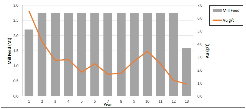
Source: MMTS, 2023
| 1.12.3 | Pit Dimensions and Slope Design |
The Company is proposing to mine ore
from the Courageous Lake deposit using open pit mining methods to a maximum depth of 320 m below ground surface. There will be two smaller
satellite pits located at the west crest (Phase 0 Pit) and south crest (Phase 99 Pit). General pit dimensions are shown in Table 1-5.
| Table 1-5: |
General Pit Dimensions |
| Pit |
Length
(North to South)
(m) |
Width
(East to West)
(m) |
Maximum
Depth
(m) |
Pit
Bottom Elevation
(masl) |
| Main PFS Pit |
1,370 |
705 |
320 |
105 |
| Phase 0 Pit |
230 |
130 |
40 |
385 |
| Phase 99 Pit |
280 |
300 |
60 |
395 |
Standard truck and shovel equipment
will be used to mine the pit. This PFS pit slope design study update (Tetra tech, 2023) is based on 10 m high operational benches with
final bench heights of 20 m for rock slopes, while the maximum unbenched slope height in overburden should be restricted to 5 m. It is
understood that 90-t trucks will be loaded with 12 m3 excavators.
The geotechnical, hydrogeological, and
permafrost investigations completed in 2006, 2010, 2011, and 2012, and the subsequent pre-feasibility level rock slope designs completed
in 2011 and 2024 have been completed in general accordance
with the requirements for a Level 2: Pre-feasibility slope angle study as described in “Guidelines for Open Pit Slope Design”
(Read and Stacey 2009).
| Courageous Lake Project | Page 9 |
| Pre-feasibility Study and Preliminary Economic Assessment NI 43-101 Technical Report | January 5, 2024 |
Based on the available data the following PFS level overburden
and rock slope designs are recommended.
| Table 1-6: |
Summary of 2024 Overburden Slope Design Recommendations |
| Slope
Design Element |
Value |
| Maximum Unbenched Slope Height (m) |
5 |
| Minimum Catch Bench Width (m) |
5 |
| Maximum Bench Face Angle (degrees) |
30 |
| Overall Slope Angle (degrees) |
22 |
| Minimum Thermal Cover Thickness (m) |
4 |
| Minimum Toe Setback from Rock Slope Crest (m) |
10 |
| Table 1-7: |
Summary of 2024 Pre-feasibility Pit Slope Design Recommendations |
| Wall
Sector Azimuth |
|
Slope Design Element |
166°
to 226°
South
to
Southwest
Wall |
226°
to 312° West
Wall and Tundra
Fault |
312° to 012°
Northwest to
North Wall |
012°
to 066°
North
to
Northeast
Wall |
066°
to 166 East Wall |
| Bench Face Angle (BFA) Degrees |
64 |
80 |
64 |
71 |
75 |
| Final Bench Height (m) |
20 |
20 |
20 |
20 |
20 |
| Catch Bench Width (m) |
12 |
10.7 |
12 |
10 |
10 |
| Inter-Ramp Angle (IRA) |
42.6 |
54.6 |
42.6 |
49.8 |
52.5 |
The selected flowsheet includes a three-stage
crushing circuit with the crushed product reporting to the fine ore stockpile. Ore is reclaimed to a grinding circuit consisting of a
ball mill circuit operating in closed circuit with a cyclone cluster. Ball mill overflow material reports to rougher flotation followed
by cleaner flotation. In the cleaning circuit, the concentrate grades are upgraded prior to further size reduction in a regrind ball mill
operating in closed circuit with a cyclone cluster. Cleaner tailings combine with rougher tailings for thickening before being discharged
to the CPSF. Overflow from regrind cyclones undergoes acidulation and pre-oxidation stages followed by the POX circuit that will effectively
oxidize the concentrate. The oxidized slurry is leached with cyanide and then washed in six stages through a CCD circuit. Pregnant solution
from the CCD is processed using a Merrill-Crowe treatment by adding zinc powder to precipitate gold and silver. The precious metals precipitate
is smelted on site to produce gold-silver doré bars. Leach residue from the CCD circuit is neutralized and pumped to the LRTF.
The processing plant is designed for a throughput of 2.74 Mt/a with availability of 90%.
The simplified process flow diagram for the Project is shown
in Figure 1-2.
| Courageous Lake Project | Page 10 |
| Pre-feasibility Study and Preliminary Economic Assessment NI 43-101 Technical Report | January 5, 2024 |
| Figure 1-2: |
Process Flowsheet |
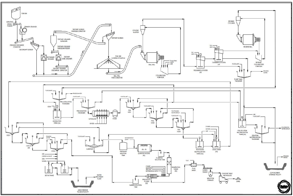
Source: Ausenco, 2023
| 1.14 | Project Infrastructure |
| 1.14.1 | Site Access, Winter Spur Road & Tibbitt to Contwoyto Winter Road |
The project site will be accessible via Courageous Lake Spur
Winter Road (CLWR), connected to Tibbitt to Contwoyto Winter Road (TCWR), which is normally open from late January/early February until
the end of March, each year.
The south to north road segments from Yellowknife to the
Project areas are as follows:
| ● | From
Yellowknife it is 72 km on the Ingram Trail to the start of the TCWR at Tibbitt Lake Meadows Security Check-in at TCWR station 0 km. |
| ● | From
the 0 km station it is 170 km to the Lockhart Lake Maintenance Camp. |
| Courageous Lake Project | Page 11 |
| Pre-feasibility Study and Preliminary Economic Assessment NI 43-101 Technical Report | January 5, 2024 |
| ● | From
the Lockhart Lake Camp it is 76 km to the turnoff to the CLWR to the Project. |
| ● | From
the CLWR turn off it is 26 km to the Project site. |
| ● | The
total length of winter road to the Project is therefore 272 km from the Tibbitt Lake start. With the further 72 km on the all-season
Ingram road it is 344 km from to the Project to Yellowknife. |
Although access to the Project is based
on the operation of the TCWR winter access road, the Government of the Northwest Territories (GNWT) is currently engaged in evaluating
and preparing regulatory applications for the first segment of a potential all-season road (Slave Geological Province Corridor Project),
from Yellowknife to Lockhart Lake Winter Road Camp, that would replace the winter road. This potential all-season road segment, should
it be constructed, would improve access and reduce capital and operating costs for the Project.
| 1.14.2 | Site Infrastructure |
Infrastructure to support the Project
includes site civil works, site facilities/buildings, on-site roads, an aerodrome, a water management system, and site electrical power
generation/distribution. Site facilities will include both mine facilities and process facilities as follows:
| ● | Mining facilities including the mine office and
dry, truck shop, tire change facility, truck wash, explosives storage and manufacturing facility, diesel fuel storage and distribution,
and coarse ore stockpile. |
| ● | Processing facilities including the primary,
secondary and tertiary crushing, run-of-mine (ROM) stockpile and reclaim conveyors, fine ore stockpile, process plant, office and laboratory,
as well as plant maintenance building. |
| ● | Mine waste and water management infrastructure
including: CPSF, LRTF, tailings distribution system, water reclaim system, downstream water management ponds, waste rock and overburden
stockpiles. |
| ● | Mine water treatment plant associated influent and discharge pipelines, and
diffuser. |
| ● | General facilities including the camp, gatehouse,
emergency response/ambulance bay, car wash, warehouse, laydowns, reagent cold storage, administration building, communications, emergency
power diesel storage, power plant, site sewage system, solid waste landfill and fresh, process and potable water storage and distribution. |
| ● | The processing plant will comprise several pre-engineered
and stick built buildings in addition to a fabric stockpile cover. |
From the start of the construction period,
a temporary construction camp will be leased, requiring a total of 560 beds to accommodate all third-party personnel within the scope
of work, including the Owner cost supervision team.
The Project requires a 204-bed accommodation
facility to support operation staff. This camp will be installed at the beginning of construction to be used for construction personnel.
The remaining 356 beds required will be covered through the temporary construction camp.
The overall site layout for the 2024
PFS is shown in Figure 1-3.
| Courageous Lake Project | Page 12 |
| Pre-feasibility Study and Preliminary Economic Assessment NI 43-101 Technical Report | January 5, 2024 |
| Figure 1-3: |
Courageous Lake PFS Site Layout |
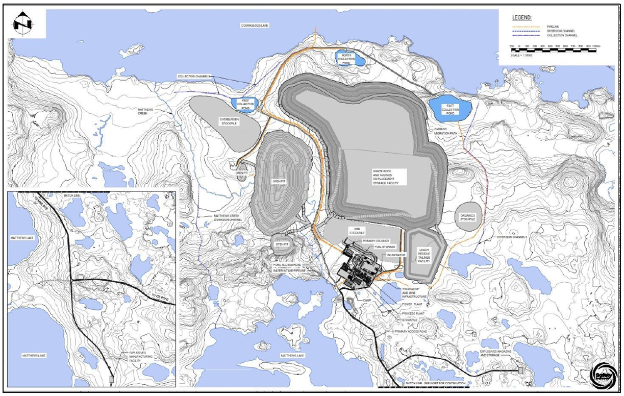
Source: Ausenco, 2023
| 1.14.3.1 | Electrical Power Demand and Supply |
The plant’s electrical demand
estimate, as used for the power supply estimates, is as shown below.
| ● | Annual plant energy consumption: 111 GWh. |
| ● | Normal operating load: 13.6 MW. |
| ● | Power factor: 0.87 lagging. |
The diesel powerplant equipment selection
for a minimum sized diesel powerplant to supply mine power will be comprised of seven modular diesel gensets, 1,800 rpm, each nominal
3.1 MW continuously rated (ancillary loads allowed for), 3 phase, 60 Hz, 13.8-kV, 0.8-PF leading, with water jacket and exhaust gas heat
recovery, with indoor day tanks and local control panels plus
networking and PLC automatic master control, with gensets mounted in double wide sound attenuated modules with fire detection, fire suppression
and H&V for arctic conditions.
| Courageous Lake Project | Page 13 |
| Pre-feasibility Study and Preliminary Economic Assessment NI 43-101 Technical Report | January 5, 2024 |
| 1.14.3.2 | Site Power Distribution |
Power will be distributed across the
site via 13.8 kV overhead lines originating from the plant’s 13.8 kV switchgear housed within the power plant electrical room.
The ball mill and oxygen plant drive systems
will be supplied via cable circuits from the plant’s primary 13.8 kV switchgear. All other process and non-Process Plant loads
will be powered via 4160 V and 600 V motor control centers (MCCs) housed within electrical rooms strategically located throughout
the plant area. Power will be stepped down to 4.16 kV, 600 V, and 120/208 V distribution, as required via grounded pad-mounted and
pole-mounted transformers.
| 1.14.4 | Co-placement Storage Facility and Leach Residue Tailings Facility |
Waste management consists of the containment
and long-term management of waste products developed during the life of mine (LOM) operations consisting of waste rock and tailings. A
deposition method trade-off study was performed between various tailings disposal technologies for the two tailings streams: flotation
and residue leach tailings from POX circuit. Based on geochemical analysis the two tailing streams need to be stored in separate facilities
since the flotation tailings are non-acid generating (NAG) and the residue leach tailings are potentially acid generating (PAG). Based
on the abundant amount of waste rock generated, it was decided to co-place the flotation tailings with the waste rock in an unlined CPSF.
The waste rock will be used to construct paddock cells to deposit slurry tailings. The advantages of the CPSF approach include the avoidance
of a separate tailings dam for flotation tailings (along with the containment embankment and lined facility), the ability to progressively
encapsulate the tailings throughout the mine life, reduced capital costs by avoiding the installation of a costly filtration plant and
reduced the operational cost and environmental footprint of transport and deposition (no need for diesel-powered dump trucks and compactors).
Free water will drain through the cells and report to an underdrain where the decant water will flow to small-lined ponds located around
the footprint of this facility. Water will either be pumped from these ponds back to the process plant or discharge into the larger collection
ponds located at the north side of this facility. The CPSF design has a capacity to store 29.7 Mt of flotation tailings and 268.1 Mt of
waste rock.
The leach residue tailings are PAG and
contain constituents of concern. Therefore, the LRTF (LRTF) is a fully geomembrane lined facility to prevent excessive seepage into the
surrounding environment. Due to the flat terrain, a ring-dike construction is required to contain the tailings. The embankment will be
a waste rock dam where the interior slope of the embankment will be covered by geomembrane liner, low permeability soil liner, and a filter
layer overlying the waste rock. The interior bottom of the facility will consist of prepared subgrade and a geomembrane liner. The LRTF
currently has capacity for 1.1 Mt. This facility also has significant expansion capability should the LOM plan be extended.
| Courageous Lake Project | Page 14 |
| Pre-feasibility Study and Preliminary Economic Assessment NI 43-101 Technical Report | January 5, 2024 |
The objective of surface water management
is to protect groundwater and surface water resources. A site-wide management strategy, encompassing the design of water management structures,
hydrology considerations, and a site-wide water balance was developed for the site. The review and interpretation of existing climate
data, encompassing factors such as precipitation, snowfall, and evaporation, are crucial for accurately estimating water balance and designing
effective water management structures. Surface water runoff that comes into contact with disturbed areas will be managed prior to being
released to the surrounding environment. Runoff from disturbed areas will be collected in gravity ditches and conveyed to ponds. Diversions
will capture non-contact water away from facilities and direct it to their natural discharge location.
Mine contact water from the open pit,
waste rock and tailings management area and residual processing water will be collected in the west or south satellite pits and pumped
from there to the mine water treatment plant (ferric co-precipitation and nitrogen nutrient removal using moving bed bioreactors) where
parameters such as arsenic, nitrate, and ammonia will be removed. Treated effluent will be pumped from the plant to Courageous Lake where
it will be discharged through a diffuser. Clean water from an undeveloped catchment to the east of the project area will be diverted away
from the waste rock and tailings management facility and directed towards Courageous Lake. Fresh water for processing of ore will be sourced
from Courageous Lake.
| 1.15 | Market Studies and Contracts |
Project economics were estimated based
on a long-term gold price of US$1,850/oz which is in accordance with consensus market forecasts from various financial institutions and
are consistent with historic prices for this commodity.
No market studies or product valuations
were completed as part of the 2024 PFS. Market price assumptions are based on a review of public information, industry consensus, standard
practices, and specific information from comparable operations in the region. The following estimations were used for project economic
analysis: 99.8% payable Au, C$5.0/oz Au transportation and refining cost, and 0.15% transportation insurance cost.
| 1.16 | Environmental, Permitting and Social Considerations |
| 1.16.1 | Environmental Considerations |
Seabridge currently maintains one
Class A land use permit, two Type B water licenses and a surface lease in good standing as well as several other ancillary permits
that enable exploration activities to occur on the Project. Advancement of the Project will require approval of the Project at
senior federal and territorial government levels prior to the commencement of construction and operations, including approval of the
mine closure and reclamation plan. The environmental assessment and permitting requirements are well-established for mining projects
in the Northwest Territories and will follow the requirements of the Mackenzie Valley Resource Management Act. The Mackenzie Valley
Environmental Impact Review Board manages the environmental assessment under the Mackenzie Valley Resource Management Act (MVRMA
S.C. 1998, c. 25). The formal assessment of the Project begins with preliminary screening conducted by the Mackenzie Valley Land and
Water Board (MVLWB), after which the Project is referred to the Mackenzie Valley Environmental Impact Review Board (MVEIRB) set up
under the MVRMA, an independent body set up under the MVRB to conduct environmental assessments of projects. The Government of
Canada continues to devolve powers to Northwest Territories in respect of natural resource management and approvals, such that Valor
Gold will continue to monitor and comply with all regulatory requirements as it advances the Project.
| Courageous Lake Project | Page 15 |
| Pre-feasibility Study and Preliminary Economic Assessment NI 43-101 Technical Report | January 5, 2024 |
Seabridge initiated environmental baseline
studies at the site by EBA Consultants in 2004 and carried out expanded baseline and monitoring programs through Rescan in 2010 –
2012. Limited baseline data collection continues by ERM Consultants to present. Seabridge and its team engage with regulatory agencies,
regional, municipal, and Indigenous governments, Treaty Nations, and Indigenous peoples as part of their effort to develop understanding
and support for the Project.
| 1.16.2 | Closure and Reclamation Considerations |
A detailed mine closure and reclamation
plan will outline the mine decommissioning process and components, post-closure land use objectives, and methods to achieve and monitor
the objectives developed for the Project. The post-closure land use plan objectives and strategies, along with criteria for informing
achievement of success, will be developed as a component of the environment assessment process. Closure and reclamation liability costs
and a financial security estimate will conform to the Northwest Territories’ policy guidance.
The mine plan will be designed with
closure and reclamation considerations. Design and layout of water management structures, salvage, and stockpiling of soils and overburden
for closure covers, incorporation of wildlife corridors, fish habitat offsetting, and long-term effects of climate change trends will
all be addressed.
Treatment of contact water is expected
to be required for up to ten years after the end of operations. The need to treat water is primarily determined by the extent of permafrost
intrusion into the waste rock and tailings masses. Once frozen, seepage of contact water from these areas will be minimal or negligible
and at that time water treatment can be discontinued.
In the closure transition period (up
to 10 years), water treatment will be limited to the open water period (May to October) each year when surface water is flowing. The annual
treatment campaign will rely on the same treatment process that was used during the operations phase.
The CPSF is constructed at the natural
angle of repose for the waste rock lifts, with set-backs this is configured to the overall closure slope angle reduce land forming of
the CPSF at closure, prior to placement of overburden cover. Tailings are covered with NAG mine rock. Revegetation with native species
will occur for restored ecosites.
Roads, totalling 9 km in length, and
pipelines totalling 14 km in length will be decommissioned when no longer required, the linear corridor land de-compacted, natural hydrology
restored, and covered or re-vegetated with native species. Care will be taken to ensure that no former linear corridors impose barriers
to caribou migration.
| Courageous Lake Project | Page 16 |
| Pre-feasibility Study and Preliminary Economic Assessment NI 43-101 Technical Report | January 5, 2024 |
Infrastructure, materials, used chemicals
and equipment no longer required, will be decommissioned and removed from site at mine closure, unless specifically required to support
the post-closure management and monitoring activities.
Water management systems are designed
to ensure that any release of contact mine water meets standards for discharge to receiving environments and a post-closure monitoring
program will be implemented and reported on in compliance with permits issued for the site.
When the mine achieves all mine closure
and reclamation objectives and criteria for success as confirmed by regulatory authorities, the mine would apply to be indemnified of
environmental liabilities and any remaining posted environmental financial securities returned.
| 1.16.3 | Permitting Considerations |
A license, permit, or other authorization
required for constructing and operating the Project and off-site infrastructure may not be issued under any federal or territorial law
unless the requirements of MVRMA have been complied with in relation to the development. Once a project has received federal ministerial
approval under the process managed by MVEIRB, it is referred to the MVLWB for processing of the original license and/or permit applications
that triggered the environmental assessment. Permitting by other agencies may also proceed.
| 1.16.4 | Social Considerations |
Valor Gold will strive to establish
collaborative and cooperative relationships with relevant Treaty, First Nations, and Métis people (as identified by the Crown),
other communities, and interested stakeholders. Valor Gold recognizes that its social license to operate is dependent on being a good
corporate citizen and neighbor to all groups with interests in the region. Valor Gold further recognizes that Indigenous groups maintain
a strong stake in both cultural and economic activity in the NWT and are closely involved in the regulation and permitting activities.
Valor Gold will continue Seabridge’s efforts to document aspects of its engagement efforts and activities.
Valor Gold is committed to a process
that ensures:
| ● | communities benefit from employment, training, and contracting opportunities; |
| ● | potential environmental impacts are mitigated; |
| ● | social concerns are accommodated in project design and management through
best efforts; and |
| ● | commitments are respected and enacted upon. |
| 1.17 | Capital and Operating Cost |
| 1.17.1 | Capital Cost Estimate |
The capital and operating cost estimates
conform to Class 4 guidelines for a PFS-level estimate with a -20%/ +25% accuracy according to AACE International. Both estimates were
developed in Q4 2023 C$ based on the proposed design for the Project, with input data from
budgetary quotations for equipment, service contracts, and construction contracts; as well as Ausenco’s in-house database of similar
projects and studies, which includes experience from similar operations. Pricing has been converted to US$ for use in financial analyses
and publication within this report using the C$ to US$ exchange rate of 0.74.
| Courageous Lake Project | Page 17 |
| Pre-feasibility Study and Preliminary Economic Assessment NI 43-101 Technical Report | January 5, 2024 |
The estimate includes mining, processing,
on-site infrastructure, tailings and waste rock facilities, off-site infrastructure, project indirect costs, project delivery, owner’s
costs, and contingency. The total capital cost summary is presented in Table 1-8. The total initial capital cost for the Project is US$747
M and LOM sustaining costs are US$293 M. Closure costs are estimated at US$72 M, with salvage credits of US$19 M.
| Table 1-8: |
Summary of Total Capital Costs |
| WBS Description |
Initial (US$M) |
Sustaining
(US$M) |
Total Cost
(US$M) |
| Mining |
89 |
156 |
245 |
| Process Plant |
204 |
48 |
252 |
| Tailings Facility |
35 |
21 |
56 |
| On-Site Infrastructure |
98 |
11 |
109 |
| Off-Site Infrastructure |
45 |
37 |
82 |
| Subtotal Direct Costs |
471 |
273 |
744 |
| Project Indirects |
146 |
6 |
153 |
| Owner’s Costs |
25 |
- |
25 |
| Contingency |
105 |
13 |
118 |
| Project Total |
747 |
293 |
1,040 |
Note: Values may not sum due to rounding
| 1.17.2 | Operating Cost Estimate |
Operating costs include the ongoing
cost of operations related to mining, processing, tailings co-disposal, general administration activities and water treatment costs. The
estimates provided in Table 1-9 and Table 1-10 are based on a combination of first-principal calculations, experience, vendor quotes,
reference projects and factors appropriate for a PFS level of study.
| Table 1-9: |
Operating Cost Summary LOM Average (C$) |
| Overall
Site OPEX |
Annual
LOM
(C$M/a) |
Per
Tonne Milled LOM
(C$/t milled) |
TOTAL
LOM
(C$M) |
| Mining |
92.2 |
34.3 |
1,162 |
| Processing |
97.6 |
36.4 |
1,231 |
| G&A |
28.3 |
10.7 |
363 |
| Water Treatment |
2.8 |
1.1 |
53 |
| Total |
220.9 |
82.5 |
2,810 |
Note: Values may not sum due to rounding
| Courageous Lake Project | Page 18 |
| Pre-feasibility Study and Preliminary Economic Assessment NI 43-101 Technical Report | January 5, 2024 |
| Table 1-10: |
Operating Cost Summary LOM Average (US$) |
| Overall
Site OPEX |
Annual
LOM (US$M/a) |
Per
Tonne Milled LOM (US$/t milled) |
TOTAL
LOM (US$M) |
| Mining |
68.2 |
25.4 |
860 |
| Processing |
72.2 |
26.9 |
911 |
| G&A |
20.9 |
7.9 |
269 |
| Water Treatment |
2.1 |
0.8 |
39 |
| Total |
163.5 |
61.0 |
2,079 |
Note: Values may not sum due to rounding
The economic analysis was performed
assuming a 5% discount rate. On a post-tax basis, the NPV discounted at 5% is US$523M, the internal rate of return (IRR) is 20.6%, and
the payback period is 2.8 years. A summary of project economics is tabulated in Table 1-11.
| Table 1-11: |
Economic Analysis Summary Table |
| Description |
Units |
LOM
Total / Avg. |
| Gold Price |
US$/oz |
1,850 |
| FX Rate |
C$:US$ |
0.74 |
| Mine Life |
Years |
12.6 |
| Total Mill Feed |
Mt |
33.9 |
| Total Waste Mined |
Mt |
257 |
| Production |
Units |
LOM
Total / Avg. |
| Mill Feed Grade – Au |
g/t |
2.61 |
| Total Metal Content – Au |
Koz |
2,847 |
| Metal Recovery Rate – Au |
% |
89.3 |
| Total Production – Au |
koz |
2,541 |
| Average Annual Production - Au |
koz/a |
213 |
| Total Payable Metal – Au |
koz |
2,536 |
| Average Annual Production – Au |
koz/a |
201 |
| Operating
Costs |
Units |
LOM
Total / Avg. |
| Mining Cost |
US$/t mined |
3.2 |
| Mining Cost |
US$/t milled |
25.4 |
| Processing Cost |
US$/t milled |
26.9 |
| G&A Cost |
US$/t milled |
7.9 |
| Water Treatment Cost |
US$/t milled |
0.8 |
| Total Operating Cost (Excl. Closure Bonding) |
US$/t milled |
61 |
| Closure Bond Premium |
US$/t milled |
0.5 |
| Courageous Lake Project | Page 19 |
| Pre-feasibility Study and Preliminary Economic Assessment NI 43-101 Technical Report | January 5, 2024 |
| Description |
Units |
LOM
Total / Avg. |
| C1
Cash Costs1 |
US$/oz Au |
863 |
| C3
Cash Costs (AISC)2 |
US$/oz Au |
999 |
| Capital
Costs |
Units |
LOM
Total / Avg. |
| Initial Capital Cost |
US$M |
747 |
| Sustaining Capital |
US$M |
293 |
| Salvage Credit |
US$M |
19.4 |
| Closure Costs |
US$M |
72 |
| Economic
Outcomes |
Units |
Pre-Tax |
Post-Tax |
| NPV (5%) |
US$M |
843 |
523 |
| IRR |
% |
27.1 |
20.6 |
| Payback |
Years |
2.2 |
2.8 |
Note:
| 1. | Cash Costs consist of mining costs, processing costs, mine-level G&A, closure bond premiums, off-site charges, and royalties |
| 2. | All-In Sustaining Costs includes cash costs plus sustaining capital, closure costs, and salvage credits |
| 1.18.2 | Sensitivity Analysis |
A sensitivity analysis was conducted
on the base case post-tax NPV and IRR of the Project using the following variables: metal price, discount rate, total operating cost,
and initial capital cost. The results are presented in detail in Section 22.5.
Table 1-12 shows a summary of the post-tax
sensitivity to gold price.
| Table 1-12: |
Economic Sensitivity to Gold Price |
| Scenario |
Units |
Lower
Case |
Base
Case |
Spot
Case
(Dec. 3, 2023) |
High
Case |
| Gold Price |
US$/oz |
1,750 |
1,850 |
2,130 |
2,500 |
| Post Tax NPV (5% Discount Rate) |
US$M |
410 |
523 |
836 |
1,134 |
| Post-Tax IRR |
% |
17.5 |
20.6 |
28.5 |
38.2 |
| 1.19 | 2024 Preliminary Economic Assessment |
The PEA is a standalone mine plan that
has been undertaken to evaluate a conceptual expansion of the open pit below the base of the permafrost after the PFS has been completely
mined out. The Mineral Resources used in the 2024 PEA mine plan are exclusive of the pits mined out in the 2024 PFS plan and the associated
Mineral Reserves or Mineral Resources inside of the 2024 PFS pits.
| Courageous Lake Project | Page 20 |
| Pre-feasibility Study and Preliminary Economic Assessment NI 43-101 Technical Report | January 5, 2024 |
The
PEA is preliminary in nature and includes Inferred Mineral Resources that are considered too speculative geologically to have the economic
considerations applied to them that would enable them to be categorized as Mineral Reserves, and there is no certainty that the results
of the PEA will be realized. Mineral Resources in the PEA mine plan are not Mineral Reserves and do not have demonstrated economic viability.
The PEA utilizes Measured, Indicated,
and Inferred Mineral Resources in mine planning. The PEA open pit mining is a conventional truck-shovel operation which utilizes 227 t
class autonomous trucks loaded by 22 m3 diesel hydraulic shovels. Selective mining with smaller loading equipment on 5 m benches
is used in the mineralization zones to reduce dilution and increase the head grade to the mill.
| 1.19.3 | Mine Production Plan |
The mill throughput is planned as 7,500
t/d and the total PEA mill feed is 43.5 Mt. Figure 1-4 shows the mill feed tonnes and grades in the PEA mine plan.
| Figure 1-4: |
Courageous Lake Mill Feed Production Schedule |
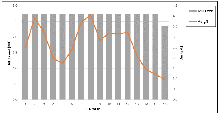
Source: MMTS, 2023
Based on the available information,
the process flowsheet developed for the Courageous Lake mineralization is considered appropriate for the 2024 PEA.
| Courageous Lake Project | Page 21 |
| Pre-feasibility Study and Preliminary Economic Assessment NI 43-101 Technical Report | January 5, 2024 |
The metallurgical performance parameters for Courageous Lake deposit
are projected based on the metallurgical test results obtained from various test programs that are summarized in the metallurgical test
work section.
The plant is designed for a throughput
of 7,500 t/d with availability of 90%. The crusher plant circuit design is set at 65% availability and the gold room availability is set
at 52 weeks/a.
The proposed plant includes a three-stage
crushing circuit followed by a grinding circuit consisting of a ball mill circuit operating in closed circuit with a cyclone cluster.
Ball mill cyclone overflow material reports to a flotation circuit consisting of rougher and cleaner flotation circuits. In the cleaning
circuit, the concentrate is upgraded prior to further size reduction in a regrind ball mill operating in closed circuit with a cyclone
cluster. Cleaner tailings combine with rougher tailings for thickening before being discharged to the CPSF. Overflow from regrind cyclones
undergoes acidulation and pre-oxidation stages prior to the POX circuit. The oxidized slurry is leached and then washed in six-stages
through a CCD circuit. The resulting pregnant solution will be processed using a Merrill-Crowe treatment by adding zinc powder to precipitate
gold and silver. The precious metals precipitate will be smelted on site to produce gold-silver doré bars.
| 1.19.5 | 2024 PEA Capital and Operating Costs |
The total initial capital cost for the
2024 PEA is US$529 M and LOM sustaining costs are US$450 M. Closure costs are estimated at US$72 M.
The total operating costs for the 2024 PEA is US$83/t milled.
| 1.19.6 | 2024 PEA Economic Analysis |
Readers are cautioned that the PEA is
preliminary in nature. It includes inferred mineral resources that are considered too speculative geologically to have the economic considerations
applied to them that would enable them to be categorized as mineral reserves, and there is no certainty that the PEA will be realized.
The economic analysis was performed
assuming a 5% discount rate discounted to the start of PFS construction. On a post-tax basis, the NPV discounted to the start of the PFS
mine at 5% is US$104 M. The total mill feed is 43.5 Mt with a mill feed grade of 2.62 g/t. The total gold recovered is 3,267 koz.
| Table 1-13: |
2024 PEA Economic Sensitivity to Gold Price and Discount Rate |
| Scenario |
Units |
Lower
Case |
Base
Case |
Spot
Case
(Dec. 3, 2023) |
High
Case |
| Gold Price |
US$/oz |
1,750 |
1,850 |
2,130 |
2,500 |
| NPV (5% Discount Rate) |
US$M |
23 |
104 |
324 |
604 |
| IRR1 |
% |
5.6 |
7.8 |
14.2 |
22.3 |
Note: Discounted to start of 2024 PFS mine construction
| Courageous Lake Project | Page 22 |
| Pre-feasibility Study and Preliminary Economic Assessment NI 43-101 Technical Report | January 5, 2024 |
| 1.20 | Conclusions and Interpretations |
The Proven and Probable mineral reserves
for 2024 PFS the Project are estimated at 33.9 Mt ore with 2.8 Moz contained gold producing 2.5 Moz of gold at an average of 201,000 oz/a.
Based on the assumptions and parameters
presented in this report, the 2024 PFS shows positive economics (i.e. US$523 M post-tax NPV5% and 20.6% post-tax IRR). The PFS supports
a decision to advance the project to the feasibility stage of development.
The standalone 2024 PEA demonstrates
the potential ability for the Project mine plan to expand below the base of the permafrost after the 2024 PFS plan has been completed,
thus demonstrating asset longevity. The PEA is preliminary in nature and includes Inferred Mineral Resources that are considered too speculative
geologically to have the economic considerations applied to them that would enable them to be categorized as Mineral Reserves, and there
is no certainty that the results of the PEA will be realized. Mineral Resources in the PEA mine plan are not Mineral Reserves and do not
have demonstrated economic viability.
The Project demonstrates positive economics,
shown by the results presented in this technical report. The recommended work will define, refine and drill further targets along the
Tundra-Salmita trend, and additional drilling of the Walsh Lake deposit to convert inferred resources into indicated and inclusion in
the mineral reserves. Table 1-14 summarizes the proposed budget to complete the recommended work program.
| Table 1-14: |
Recommended Work Program |
| Program
Component |
Summer
2026 (C$) |
Winter
2027 (C$) |
Total
(C$) |
| Camp |
199,000 |
1,260,000 |
1,459,000 |
| Helicopters |
270,000 |
723,000 |
993,000 |
| Geophysics |
150,000 |
- |
150,000 |
| Drilling |
- |
1,260,000 |
1,260,000 |
| Assays and Analysis |
6,000 |
343,000 |
349,000 |
| Staff |
175,000 |
242,000 |
417,000 |
| IT |
71,000 |
53,000 |
124,000 |
| Travel and Expenses |
74,000 |
59,000 |
133,000 |
| Environment and Permitting |
130,000 |
13,000 |
143,000 |
| Total |
1,075,000 |
3,953,000 |
5,028,000 |
| Courageous Lake Project | Page 23 |
| Pre-feasibility Study and Preliminary Economic Assessment NI 43-101 Technical Report | January 5, 2024 |
Seabridge Gold Inc. (Seabridge) commissioned
Ausenco Engineering Canada ULC. and Ausenco Sustainability ULC. (collectively Ausenco) to compile a PFS (2024 PFS) of the Courageous Lake
Project (the Project). The 2024 PFS has been prepared in accordance with the Canadian disclosure requirements of National Instrument 43-101
(NI 43-101) and in accordance with the requirements of Form 43-101 F1. Additionally, a separate Preliminary Economic Assessment (2024
PEA) has been conducted to assess a conceptual layback of the mine within the Courageous Lake deposit after the completion of the 2024
PFS mine plan. It is important to note that none of the Mineral Resources included in the 2024 PEA mine plan have been utilized in the
2024 PFS mine plan.
Seabridge issued news releases dated
December 16, 2025 and January 21, 2026, announcing its intention to spin out its 100% interest in the Project. Seabridge is advancing
a structure whereby all the shares in Valor Gold, the spin-out entity and a wholly-owned subsidiary of Seabridge, would be distributed
to Seabridge shareholders pursuant to a court-approved plan of arrangement under the Canada Business Corporations Act. The responsibilities
of the engineering companies contracted by Seabridge to prepare this report are as follows:
| ● | Ausenco managed and coordinated the development
of this report, developed PFS-level designs for the process plant, tailings facilities and general on-site infrastructure, developed the
consolidated cost estimates, and prepared the economic analysis. |
| ● | Moose Mountain Technical Services Ltd. (MMTS)
developed the mineral resource estimate (MRE) and designed the open pit mine, mine production schedule, and mine capital and operating
costs. In addition, MMTS completed the work related to property description, accessibility, local resources, geological setting, deposit
type, exploration work, drilling, sample preparation and analysis, and data verification. |
| ● | ERM Consultants Canada Ltd. (ERM) conducted a
review of the environmental studies and permitting information. |
| ● | SRK Consulting (Canada) Inc. (SRK) prepared the
design and cost estimate for the water treatment plant. |
| ● | WN Brazier Associates Inc. (WN Brazier) designed
the site power generation facilities and cost estimates. |
| ● | Tetra Tech Canada Inc. (Tetra Tech). prepared
the open pit and overburden slope designs and stability assessments, completed a gap analysis and conformance review of the previous PFS-level
open pit slope designs completed in 2011, and provided an updated airstrip scope from earlier recommendations offered in the 2012 PFS
(including material take-offs used for the cost estimate). |
The report has been prepared in connection
with the proposed spin-out of Seabridge’s 100% interest in the Courageous Lake project into Valor Gold.
| Courageous Lake Project | Page 24 |
| Pre-feasibility Study and Preliminary Economic Assessment NI 43-101 Technical Report | January 5, 2024 |
The qualified persons (QPs) for this
technical report and the report sections for which each QP is responsible are listed in Table 2-1. By virtue of their education, experience,
professional association membership, and independence from Seabridge and Valor Gold, each is considered a QP as defined by NI 43-101.
| Table 2-1: |
Report Contributors |
| Qualified
Person |
Professional
Designation |
Position |
Employer |
Independent
of Seabridge &
Valor Gold |
| Kevin Murray |
P. Eng. |
Manager, Process Engineering |
Ausenco Engineering
Canada ULC. |
Yes |
| Jonathan Cooper |
P. Eng. |
Water Resources Engineer |
Ausenco Sustainability
ULC. |
Yes |
| Aleksandar Spasojevic |
P. Eng. |
Geotechnical Practice Lead |
Ausenco Sustainability
ULC. |
Yes |
| Allan George Strandberg |
P. Eng. |
Senior Arctic Engineer |
Ausenco Sustainability
Canada ULC. |
Yes |
| Harold Rolf Schmitt |
P. Geo. |
Technical Director, Permitting |
ERM Consultants
Canada Ltd. |
Yes |
| Sue Bird |
P. Eng. |
Principal and VP, Resources |
Moose Mountain
Technical Services Ltd. |
Yes |
| Jesse J. Aarsen |
P. Eng. |
President & Principal, Mine
Engineering |
Moose Mountain
Technical Services Ltd. |
Yes |
| Walter Neil Brazier |
P. Eng. |
Owner |
WN Brazier Associates
Inc. |
Yes |
| Hassan Ghaffari |
P. Eng. |
Director of Metallurgy |
Tetra Tech Canada Inc. |
Yes |
| Cameron Clayton |
P. Eng.
P. Geo. |
Principal Rock Mechanics Engineer |
Tetra Tech Canada Inc. |
Yes |
| Sorensen Jensen |
P. Eng. |
Principal Consultant,
Environmental Engineering |
SRK Consulting
(Canada) Inc. |
Yes |
| 2.4 | Site Visits and Scope of Personal Inspection |
A summary of the site visits completed
by the QPs is presented in Table 2-2. No material work has been done on the Project since the last site inspection.
| Qualified
Person |
Date
of Site Visit(s) |
| Aleksandar Spasojevic |
June 21, 2023 |
| Harold Rolf Schmitt |
July 4, 2019
June 21, 2023
|
| Courageous Lake Project | Page 25 |
| Pre-feasibility Study and Preliminary Economic Assessment NI 43-101 Technical Report | January 5, 2024 |
| Qualified
Person |
Date
of Site Visit(s) |
| Jesse Aarsen |
June 21, 2023 |
| Sue Bird |
June 21, 2023 |
|
Neil Brazier |
August 24, 2010,
August 21-28, 2012,
August 11-13, 2013,
October 28-30, 2013,
June 6-12, 2014,
August 10-11 & 14-15, 2015,
July 25-28, 2016,
August 10-12, 2017,
July 3-5, 2018 |
| Cameron Clayton |
July 13-16 & 20-23, 2010 |
| 2.4.2 | Site Inspection by Aleksandar Spasojevic, P. Eng. |
Aleksandar Spasojevic visited the site on June 21, 2023.
Activities during the site visit included the following:
| ● | Reviewing site geotechnical parameters. |
| ● | Visiting the proposed paddock, BIOX and plant site locations. |
| 2.4.3 | Site Inspection by Harold Rolf Schmitt, P. Geo. |
Harold Rolf Schmitt visited the site twice, most recently
on June 21, 2023. Activities during the site visit included the following:
| ● | A field visit to proposed major component areas including open pit, tailing
storage facility, stockpiles. |
| ● | Accompanying and discussions with mining engineering and geotechnical engineering
specialists on site. |
| ● | Observing wildlife (caribou, moose, muskox), Matthews Creek fish habitat,
and meteorological station. |
| ● | Observing existing workings (Peggy’s Pit). |
| 2.4.4 | Site Inspection by Jesse Aarsen, P. Eng. |
Jesse Aarsen visited the site on June 21, 2023. Activities
during the site visit included inspecting the following:
| ● | Pit and dump footprint areas. |
| ● | Matthews creek inlet and potential diversion alignment. |
| ● | Airstrip and access road between the airstrip and the mining area. |
| ● | Existing workings (Peggy’s Pit). |
| Courageous Lake Project | Page 26 |
| Pre-feasibility Study and Preliminary Economic Assessment NI 43-101 Technical Report | January 5, 2024 |
| 2.4.5 | Site Inspection by Sue Bird, P. Eng. |
Sue Bird visited the site on June 21, 2023. Activities during
the site visit included the following:
| ● | Verifying several drillhole locations in the Courageous Lake and Walsh Lake
deposit areas. |
| ● | Examining core from each deposit with the Seabridge geologist and getting
an overview of site geology. |
| ● | Visiting the camp, the old shaft location and the location of existing workings
(Peggy’s Pit). |
| 2.4.6 | Site Inspection by Neil Brazier, P. Eng. |
Neil Brazier has visited the site on multiple occasions,
most recently on July 3-5, 2018. Activities during the site visits included the following:
| ● | General site inspections. |
| ● | Wind resource tower inspection and maintenance. |
| ● | Potential wind farm siting. |
| ● | 10-kW wind test turbine siting and installation. |
| ● | Test wind turbine maintenance. |
| 2.4.7 | Site Inspection by Cameron Clayton, P. Eng., P. Geo. |
Cameron Clayton completed a personal inspection of the Property
from July 13 to July 16, 2010, and from July 20 to July 23, 2010. Activities during the site visits included the following:
| ● | Developing, directing, supervising, and reviewing
the geotechnical core logging and core orientation, collecting core samples for laboratory strength testing being carried out by Golder
personnel under his direct supervision and training in 2010, 2011 and 2012 to support pre-feasibility level pit slope design. |
| ● | Planning the ground temperature cable (GTC) installations,
electrical conductivity probe installations, and vibrating wire piezometer installations completed by Golder in 2010 and 2011. |
| ● | Reviewing drill core from boreholes designated
for geotechnical logging to assess the rock mass quality for use in the open pit design. |
| ● | Completing a site visit to Peggy’s Pit
for the purpose of surface geotechnical and structural geological mapping to compare structural orientations with those obtained from
oriented drill core. |
| ● | Recording additional resistivity data in 2010
from the historical GTCs installed at the site for the purpose of updating the geothermal profiles. |
| Courageous Lake Project | Page 27 |
| Pre-feasibility Study and Preliminary Economic Assessment NI 43-101 Technical Report | January 5, 2024 |
This technical report has three significant dates, as follows:
| ● | Courageous Lake Project Mineral Resource Estimate: January 5, 2024. |
| ● | Courageous Lake Project Mineral Reserve Estimate: January 5, 2024. |
| ● | Financial analysis: January 5, 2024. |
The effective date of this PFS report
is based on the date of the financial analysis, which is January 5, 2024, and the report date is March 23, 2026.
| 2.6 | Information Sources and References |
This technical report is based on internal
company reports, maps, published government reports, and public information as listed in Section 27 along with information cited in Section
3.
The authors are not experts with respect
to legal, socio-economic, land title, or political issues, and are therefore not qualified to comment on issues related to the status
of permitting, legal agreements, and royalties. Information related to these matters has been provided directly by Seabridge and includes,
without limitation, validity of mineral tenure, status of environmental and other liabilities, and permitting to allow completion of environmental
assessment work.
| 2.6.2 | Conformance Review and Gap Assessment of Golder 2011 Pre-feasibility Level Pit Slope Design Criteria |
Tetra Tech completed a conformance review
and gap assessment of the Golder 2011 pre-feasibility level pit slope design technical report (Tetra Tech, 2023a). The objective of the
review was to evaluate the previous pit slope design technical study and report completed by Golder (2011a) for conformance with current
industry practices and guidelines for the development of pre-feasibility level pit slope design criteria. The review concluded that the
previous pit slope design report generally complied with current industry practices and guidelines. Gaps and data deficiencies to be addressed
during future engineering design studies were identified.
| 2.6.3 | Previous Technical Reports |
The Project has been the subject of previous technical reports,
as summarized in Table 2-3.
| Table 2-3: |
Summary of Previous Technical Reports |
| Reference |
Company |
Technical
Report |
| Wardrop Engineering Inc., 2008 |
Seabridge |
Courageous Lake Preliminary Economic Assessment |
| Wardrop Engineering Inc., 2011 |
Seabridge |
Courageous Lake Updated Preliminary Economic Assessment 2011 |
| Tetra Tech, 2012 |
Seabridge |
Pre-feasibility Study - Courageous Lake Project |
| Courageous Lake Project | Page 28 |
| Pre-feasibility Study and Preliminary Economic Assessment NI 43-101 Technical Report | January 5, 2024 |
| 2.7 | Currency, Units, Abbreviations and Definitions |
All units of measurement in this report
are metric and all currencies are expressed in Canadian dollars (symbol: C$ or currency: CAD) unless otherwise stated. Contained gold
metal is expressed as troy ounces (oz), where 1 oz = 31.1035 g. All material tonnes are expressed as dry metric tonnes (dmt) unless stated
otherwise. A list of abbreviations and acronyms is provided in Table 2-4, and units of measurement are listed in Table 2-5.
| Table 2-4: |
Abbreviations and Acronyms |
| Abbreviation |
Description |
| AA |
atomic absorption spectroscopy |
| ACME |
ACME Laboratories |
| ALS |
ALS Laboratories |
| ANFO |
ammonium nitrate fuel oil |
| ASTM |
American Society for Testing and Materials |
| Au |
gold |
| Az |
azimuth |
| BIF |
banded iron formation |
| BIOX |
bio-oxidation |
| BWi |
bond ball mill work index |
| C$:US$ |
Canadian American exchange rate |
| CCD |
Counter current decantation |
| CIM |
Canadian Institute of Mining, Metallurgy and Petroleum |
| CIM |
CIM Definition Standards for Mineral Resources and Mineral Reserves 2014 |
| CIP |
carbon in pulp |
| CLGB |
Courageous-MacKay Lake Greenstone Belt |
| CLWR |
Courage Lake Mine Spur Winter Road |
| CNA |
Cyanide amenability |
| CNWAD |
weak acid dissociable cyanide |
| CoG |
cut-off grade |
| CPP |
cumulative probability plots |
| CPSF |
co-placement storage facility |
| CRM |
certified reference material |
| CSIR |
Council of Scientific and Industrial Research |
| CV |
Coefficient of Variation |
| CWi |
Bond crusher work index |
| CZ |
Combined Zone |
| DCIP |
direct current resistivity and induced polarization |
| DDH |
diamond drill hole |
| DGPS |
Differential global positioning system |
| Courageous Lake Project | Page 29 |
| Pre-feasibility Study and Preliminary Economic Assessment NI 43-101 Technical Report | January 5, 2024 |
| Abbreviation |
Description |
| DS |
direct shear test |
| EBA |
EBA Consultants |
| EC |
Electrical conductivity |
| E-GRG |
extended gravity recoverable gold |
| EM |
electromagnetic |
| ERM |
ERM Consultants Canada Ltd. |
| FA |
fire assay |
| FAT |
felsic ash tuff |
| FEL |
felsic volcanic rocks |
| FET |
federal excise tax |
| FoS |
Factor of Safety |
| FS |
feasibility study |
| G&A |
general and administration |
| G&T |
G&T Metallurgical Services Ltd. |
| GPR |
gross production royalty |
| GME |
General mine expense |
| Golder |
Golder Associates Ltd. |
| GQCV |
greenstone-hosted quartz-carbonate vein deposits |
| GRAV |
gravimetric finish method |
| GTC |
Ground temperature cable |
| GVW |
Gross vehicle weight |
| HANFO |
Heavy ammonium nitrate fuel oil |
| HCN |
Hydrogen cyanide |
| IBC |
Intermediate bulk containers |
| ICP |
inductively coupled plasma |
| ICP-OES |
inductively coupled plasma - optical emission spectrometry |
| ID2 |
inverse distance squared |
| ID3 |
inverse distance cubed |
| IOCG |
iron oxide copper gold |
| IP |
induced polarization |
| IRGS |
intrusion-related gold system |
| ISO |
International Organization for Standardization |
| ISRM |
International Society of Rock Mechanics |
| LG |
Lerch-Grossman |
| LiDAR |
light detection and ranging |
| LRTF |
Leach Residue Tailings Facility |
| LOM |
life of mine |
| LUP |
land use permit |
| Courageous Lake Project | Page 30 |
| Pre-feasibility Study and Preliminary Economic Assessment NI 43-101 Technical Report | January 5, 2024 |
| Abbreviation |
Description |
| MLGB |
Matthews Lake Greenstone Belt |
| MC |
master composite |
| MCF |
mechanized cut and fill |
| MIBC |
Methyl Isobutyl Carbinol |
| MMTS |
Moose Mountain Technical Services |
| MPSO |
mine plan strategic optimizer |
| MRE |
mineral resource estimate |
| MVEIRB |
Mackenzie Valley Environmental Impact Review Board |
| NAD 83 |
North American Datum of 1983 |
| NAG |
non-acid generating |
| NBC |
National Building Code |
| NGI |
Norwegian Geotechnical Institute |
| NI 43-101 |
National Instrument 43-101 (Regulation 43-101 in Quebec) |
| NN |
nearest neighbor |
| NPV |
Net present value |
| NRC |
Natural Resources Canada |
| NSP |
net smelter price |
| NSR |
net smelter return |
| NTS |
national topographic system |
| OK |
ordinary kriging |
| PAX |
Potassium amyl xanthate |
| PDX |
Placer Dome Exploration Inc. |
| PEA |
preliminary economic assessment |
| PF |
Probability of Failure |
| PFS |
Pre-feasibility Study |
| PGE |
platinum group elements |
| PLT |
Point load test |
| POX |
pressure oxidation |
| PSA |
Pit slope angles |
| Q |
Tunneling Quality Index (Barton et al. 1974) |
| QA/QC |
quality assurance/quality control |
| QP |
qualified person (as defined in National Instrument 43-101) |
| RELZ |
relative distance |
| RMI |
Resource Modeling Inc. |
| RMR76 |
Rock Mass Rating (1976) System |
| ROM |
run-of-mine |
| RQD |
rock quality designation |
| SAG |
semi-autogenous grinding |
| Courageous Lake Project | Page 31 |
| Pre-feasibility Study and Preliminary Economic Assessment NI 43-101 Technical Report | January 5, 2024 |
| Abbreviation |
Description |
| SCC |
Standards Council of Canada |
| SD |
standard deviation |
| Sd-BWI |
micro hardness or bond ball mill work index on SAG ground material |
| SEDEX |
sedimentary exhalative deposits |
| SG |
specific gravity |
| TCWR |
Tibbitt to Contwoyto Winter Road |
| TDS |
Total dissolved solids |
| Tetra Tech |
Tetra Tech Canada Inc. |
| TK |
Traditional knowledge |
| TMF |
Tailings management facility |
| TSF |
Tailings Storage Facility |
| UCS |
Unconfined Compressive Strength Test |
| UG |
underground |
| UTM |
Universal Transverse Mercator coordinate system |
| UV |
ultraviolet |
| VLF-EM |
very low frequency electromagnetic |
| VMS |
volcanogenic massive sulphide |
| VWP |
Vibrating Wire Piezometer |
| WSP |
WSP Limited (formerly Golder Associates Ltd.) |
| YGS |
Yellowknife Group Sedimentary Rocks |
| Table 2-5: |
Units of Measurement |
| Abbreviation |
Description |
| % |
percent |
| % solids |
percent solids by weight |
| CAD |
Canadian dollar (currency) |
| CAD$ |
Canadian dollar (as symbol) |
| $/t |
dollars per metric ton |
| ° |
angular degree |
| °C |
degree Celsius |
| μm |
micron (micrometer) |
| cm |
centimeter |
| cm3 |
cubic centimeter |
| d |
day |
| dmt |
dry metric tonnes |
| ft |
foot (12 inches) |
| g |
gram |
| Courageous Lake Project | Page 32 |
| Pre-feasibility Study and Preliminary Economic Assessment NI 43-101 Technical Report | January 5, 2024 |
| Abbreviation |
Description |
| g/cm3 |
gram per cubic centimeter |
| GWh |
gigawatt hour |
| g/L |
gram per liter |
| g/t |
gram per metric ton (tonne) |
| h |
hour (60 minutes) |
| ha |
hectare |
| hPa |
hectopascal |
| Hz |
hertz |
| kb |
kilobyte |
| kg |
kilogram |
| kg/t |
kilogram per tonne |
| km |
kilometer |
| km2 |
square kilometer |
| kPa |
kilopascal |
| kt |
kilotonne |
| kV |
kilovolt |
| kW |
kilowatt |
| kWh/t |
kilowatt-hour per tonne |
| L |
liter |
| lb |
pound |
| m,
m2, m3 |
meter, square meter, cubic meter |
| M |
million |
| Ma |
million years (annum) |
| masl |
meters above mean sea level |
| m bgs |
meters below ground surface |
| mg |
milligram |
| mg/L |
milligram per liter |
| mm |
millimeter |
| Mm3 |
Million cubic meter |
| Moz |
million (troy) ounces |
| m/s |
meter per second |
| Mt |
million tonnes |
| Mt/a |
million tonnes per annum |
| MW |
megawatt |
| MWh/a |
megawatt hours per annum |
| oz |
troy ounce |
| oz/t |
ounce (troy) per tonne |
| oz/ton |
ounce (troy) per short ton (2,000 lbs) |
| Courageous Lake Project | Page 33 |
| Pre-feasibility Study and Preliminary Economic Assessment NI 43-101 Technical Report | January 5, 2024 |
| Abbreviation |
Description |
| ppb |
parts per billion |
| ppm |
parts per million |
| t |
metric tonne (1,000 kg) |
| ton |
short ton (2,000 lbs) |
| t/d |
metric tonnes per day |
| t/h |
metric tonnes per hour |
| USD |
US dollars (currency) |
| US$ |
US dollars (symbol) |
| W |
watt |
| W/m2 |
watts per square meter |
| wmt |
wet metric tonne |
| y |
year |
| Courageous Lake Project | Page 34 |
| Pre-feasibility Study and Preliminary Economic Assessment NI 43-101 Technical Report | January 5, 2024 |
| 3 | RELIANCE ON OTHER EXPERTS |
The qualified persons (QPs) have relied
upon other expert reports that provided information regarding mineral rights, surface rights, property agreements, royalties, environmental,
permitting, social license, closure, taxation, and marketing for sections of this Report.
| 3.2 | Property Agreements, Mineral Tenure, Surface Rights and Royalties |
The QPs have not independently reviewed
ownership of the Project area and any underlying property agreements, mineral tenure, surface rights, or royalties. The QPs have fully
relied upon, information derived from Seabridge and legal experts retained by Seabridge and Valor Gold for this information through the
following documents:
| ● | The Claim Group Inc. (TCG), December 5, 2023. Seabridge Gold (NWT) Inc. –
Courageous Lake Property, 3pp. |
This information is used in Section
1.2, Section 4, and Section 25.1.2 of this report. The information is also used in support of Sections 14, 15 and Section 24 of this report.
| 3.3 | Environmental, Permitting, Closure, and Social and Community Aspects |
The QPs have not independently reviewed
the environmental information. The QPs have fully relied upon environmental information derived from experts retained by Seabridge contained
in the following documents:
| ● | Seabridge Gold (NWT) Inc., was relied upon for
land use (exploration) and water license permitting, records of government and Indigenous engagement as reported in: Courageous Lake Project
– Exploration Work Plan, Prepared to Support One Type “A” Land Use Permit and Two “Type B” Water License
Applications. September 2019. This information is used in Section 1.16, 20 and 20.1 of the Report. |
| ● | Mr. Daniel Walker, P.P.C.A., and David LeBeau,
M.A. of ERM Consultants Canada Ltd., have been relied upon for the report titled: Courageous Lake Project – Final Report on Northwest
Territories Act Class 2 Archaeologist’s Permit # 2022-003. June 23, 2023. This information is used in Section 1.16, 20 and 20.1
of the Report. |
| ● | Dr. Greg Sharam of ERM Consultants Canada Ltd.,
was relied upon for the report titled: Draft Courageous Lake Project – Caribou Camera Report, 2023. November 24, 2023. This information
is used in Section 1.16, 20 and 20.1 of the Report. |
The QPs have not independently reviewed
the taxation information. The QPs have fully relied upon taxation information derived from experts retained by Seabridge contained in
the following document:
| ● | A letter authored by PricewaterhouseCoopers LLP (“PwC’) with the title: “NI 43-101
Technical Report Prepared for Seabridge Gold Inc. – Taxation Narrative,” dated January 3, 2024. |
PwC is an Ontario limited liability partnership, which is
a member firm of PricewaterhouseCoopers International Limited, each member firm of which is a separate legal entity.
This information is used in Section 22 and Section 24 of
this Report.
| Courageous Lake Project | Page 35 |
| Pre-feasibility Study and Preliminary Economic Assessment NI 43-101 Technical Report | January 5, 2024 |
| 4 | PROPERTY DESCRIPTION AND LOCATION |
The Courageous Lake Property is
located 240 km northeast of Yellowknife NWT, Canada (Figure 4-1). The center of the deposit is located at NAD83 Universal Transverse Mercator
(UTM) coordinates 486,700 East and 7,109,600 North.
The property is a collection of
mineral leases that trend north- south along the 54 km length of the Courageous Lake Greenstone Belt (CLGB) in the Slave Structural Province.
The property includes the past gold-producing properties of the Salmita mine operated by Giant Yellowknife Mines, and the Tundra mine
operated by Royal Oak Mines.
There are no significant risks
to the property title, or the ability to do work on the property that the QP is aware of, other than those discussed below.
Upon acquiring the Courageous Lake
project, Seabridge assigned its right to its wholly owned subsidiary, Seabridge NWT.
Since the December 16, 2025, announcement
Seabridge has established a new wholly owned subsidiary (Valor Gold Corp) which will own 100% of the shares in Seabridge NWT (the entity
holding the various licences and permits). The spinout will involve spinning out and list Valor Gold (and indirectly its subsidiary) with
100% of Valor Gold’s shares being distributed to Seabridge shareholders.
Seabridge retained The Claims Group
(TCG), an Ontario-based consultancy that provides various land status services. TCG acts as an agent on behalf of Seabridge and their
wholly owned subsidiary, Seabridge Gold (NWT) Inc. The following italicized information was taken from a memorandum prepared for Seabridge
by Mr. John L. Brassard, President of TCG:
As of January 2024, the Courageous
Lake property is comprised of 85 Northwest Territorial Mining Leases and 4 Federal Mining Leases having a combined area of 50,239.96 hectares.
Seventeen of the Mining Leases
were acquired by Seabridge through a Purchase and Sale Agreement with Newmont Canada Limited (51%) and Total Resource Canada Limited (Total)
(49%) dated July 16, 2002. These 17 Mining Leases are encumbered by two royalty agreements (G21883 & G21885) and two debentures (G21884
& G21886) registered in favour of Newmont and Total, respectively. Newmont’s interests were subsequently assigned to Franco-Nevada
Canada Corp. on January 30, 2008 (G22235 & G22238). The Property is subject to a 2km Area of Interest from and parallel to all exterior
boundaries and Mining Leases.
| Courageous Lake Project | Page 36 |
| Pre-feasibility Study and Preliminary Economic Assessment NI 43-101 Technical Report | January 5, 2024 |
In June 2002, Seabridge purchased
the property from the Newmont-Total Tundra Joint Venture, with Newmont retaining a 2% net smelter royalty and the right to receive conditional
payments totalling US$3,000,000, which have now been fully paid.
Mining Lease ML5218 (Red 25)
was optioned by Seabridge Gold Northwest Territories (Seabridge (NWT)) from Bathurst Inlet Developments (1984) Limited in 2004 through
an Option to Purchase Agreement and was assigned to Seabridge (NWT) on November 2, 2018 (G35528).
All of the Mining Leases
are currently recorded 100% to Seabridge (NWT). Other than the royalties and the encumbrances relating to them, there are no other liens,
charges encumbrances, etc. registered against title to any of the Mining Leases.
The properties were located
by professional surveyors under the direction of TGC. High-precision differential GPS instruments were employed to locate corners and
side lines of claims (TetraTech, 2012).
The annual mining lease rents for the Courageous Lake Property
are current and paid through to the report date of this technical report.
| Courageous Lake Project | Page 37 |
| Pre-feasibility Study and Preliminary Economic Assessment NI 43-101 Technical Report | January 5, 2024 |
| Figure 4-1: |
General Location Map of the Courageous Lake Project |
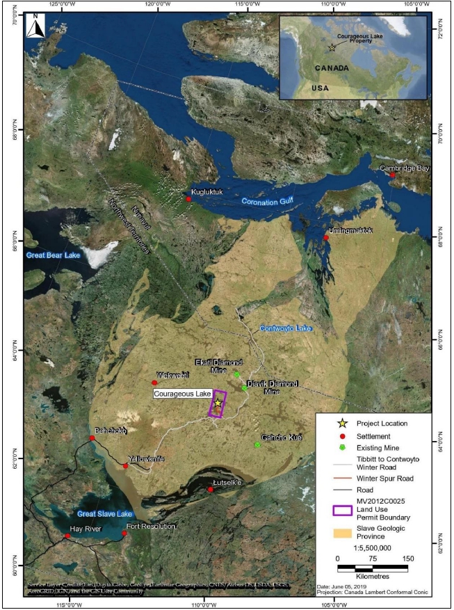
Source: Seabridge, 2019
| Courageous Lake Project | Page 38 |
| Pre-feasibility Study and Preliminary Economic Assessment NI 43-101 Technical Report | January 5, 2024 |
The Courageous Lake Mineral Leases
are provided in Table 4-1 with a plan map of the claims in Figure 4-2. The claims boundary with respect to the Courageous Lake and Walsh
Lake resource pits is illustrated in Figure 4-3, with the boundary in red and the pit outlines in black.
| Table 4-1: |
Courageous Lake Property Mineral Leases |
| Lease # |
Owner |
NTS
1 |
NTS 2 |
Anniv |
Expiry |
Hectares |
Annual Rent |
| 3357 |
Seabridge Gold (NWT) Inc. |
075M14 |
- |
26-Apr-26 |
25-Apr-32 |
764.86 |
$3,780.00 |
| 3361 |
Seabridge Gold (NWT) Inc. |
075M14 |
- |
26-Apr-26 |
25-Apr-32 |
823.13 |
$4,068.00 |
| 0010 |
Seabridge Gold (NWT) Inc. |
076D06 |
- |
18-May-26 |
18-May-43 |
994.52 |
$4,915.00 |
| 5578 |
Seabridge Gold (NWT) Inc. |
076D03 |
- |
19-May-26 |
19-May-40 |
1057.00 |
$2,642.50 |
| 5579 |
Seabridge Gold (NWT) Inc. |
076D03 |
- |
19-May-26 |
19-May-40 |
1043.00 |
$2,607.50 |
| 5580 |
Seabridge Gold (NWT) Inc. |
076D03 |
- |
19-May-26 |
19-May-40 |
1039.00 |
$2,597.50 |
| 5581 |
Seabridge Gold (NWT) Inc. |
076D03 |
- |
19-May-26 |
19-May-40 |
1027.00 |
$2,567.50 |
| 5582 |
Seabridge Gold (NWT) Inc. |
076D03 |
- |
19-May-26 |
19-May-40 |
917.00 |
$2,292.50 |
| 5583 |
Seabridge Gold (NWT) Inc. |
076D03 |
- |
19-May-26 |
19-May-40 |
1036.00 |
$2,590.00 |
| 5584 |
Seabridge Gold (NWT) Inc. |
076D03 |
- |
19-May-26 |
19-May-40 |
1044.00 |
$2,610.00 |
| 5585 |
Seabridge Gold (NWT) Inc. |
076D03 |
- |
19-May-26 |
19-May-40 |
1050.00 |
$2,625.00 |
| 5586 |
Seabridge Gold (NWT) Inc. |
076D03 |
- |
19-May-26 |
19-May-40 |
1033.00 |
$2,582.50 |
| 5587 |
Seabridge Gold (NWT) Inc. |
076D03 |
- |
19-May-26 |
19-May-40 |
1004.00 |
$2,510.00 |
| 5588 |
Seabridge Gold (NWT) Inc. |
076D03 |
076D06 |
19-May-26 |
19-May-40 |
1058.00 |
$1,645.00 |
| 5589 |
Seabridge Gold (NWT) Inc. |
076D03 |
076D06 |
19-May-26 |
19-May-40 |
1053.00 |
$2,632.50 |
| 5590 |
Seabridge Gold (NWT) Inc. |
076D03 |
076D06 |
19-May-26 |
19-May-40 |
1080.00 |
$2,700.00 |
| 5591 |
Seabridge Gold (NWT) Inc. |
076D03 |
076D06 |
19-May-26 |
19-May-40 |
1035.00 |
$2,587.50 |
| 5592 |
Seabridge Gold (NWT) Inc. |
076D03 |
076D06 |
19-May-26 |
19-May-40 |
1056.00 |
$2,640.00 |
| 5593 |
Seabridge Gold (NWT) Inc. |
076D06 |
- |
19-May-26 |
19-May-40 |
79.40 |
$198.50 |
| 5594 |
Seabridge Gold (NWT) Inc. |
076D06 |
- |
19-May-26 |
19-May-40 |
174.00 |
$435.00 |
| 5227 |
Seabridge Gold (NWT) Inc. |
076D03 |
- |
24-May-26 |
23-May-32 |
61.51 |
$152.00 |
| 5228 |
Seabridge Gold (NWT) Inc. |
076D03 |
- |
24-May-26 |
23-May-32 |
194.65 |
$481.00 |
| 3221 |
Seabridge Gold (NWT) Inc. |
075M14 |
- |
16-Jun-26 |
15-Jun-28 |
236.34 |
$1,168.00 |
| 3223 |
Seabridge Gold (NWT) Inc. |
076D03 |
- |
23-Jun-26 |
23-Jun-29 |
491.29 |
$2,428.00 |
| 3222 |
Seabridge Gold (NWT) Inc. |
076D03 |
- |
24-Jun-26 |
24-Jun-29 |
367.05 |
$1,814.00 |
| 3228 |
Seabridge Gold (NWT) Inc. |
075M14 |
- |
30-Jun-26 |
30-Jun-29 |
953.85 |
$4,714.00 |
| 3229 |
Seabridge Gold (NWT) Inc. |
076D03 |
- |
30-Jun-26 |
30-Jun-29 |
641.43 |
$3,170.00 |
| 3230 |
Seabridge Gold (NWT) Inc. |
076D03 |
- |
30-Jun-26 |
30-Jun-29 |
209.63 |
$1,036.00 |
| 3251 |
Seabridge Gold (NWT) Inc. |
076D06 |
- |
30-Jun-26 |
30-Jun-29 |
469.03 |
$2,318.00 |
| 5218 |
Seabridge Gold (NWT) Inc. |
076D03 |
- |
4-Jul-26 |
3-Jul-32 |
21.61 |
$53.40 |
| Courageous Lake Project | Page 39 |
| Pre-feasibility Study and Preliminary Economic Assessment NI 43-101 Technical Report | January 5, 2024 |
| Lease # |
Owner |
NTS 1 |
NTS 2 |
Anniv |
Expiry |
Hectares |
Annual Rent |
| 3219 |
Seabridge Gold (NWT) Inc. |
076D03 |
- |
9-Jul-26 |
8-Jul-28 |
68.03 |
$336.20 |
| 3158 |
Seabridge Gold (NWT) Inc. |
076D03 |
- |
25-Jul-26 |
24-Jul-26 |
556.85 |
$2,752.00 |
| 3159 |
Seabridge Gold (NWT) Inc. |
076D03 |
- |
25-Jul-26 |
24-Jul-26 |
216.10 |
$1,068.00 |
| 3160 |
Seabridge Gold (NWT) Inc. |
076D03 |
- |
25-Jul-26 |
24-Jul-26 |
760.00 |
$3,756.00 |
| 3161 |
Seabridge Gold (NWT) Inc. |
076D03 |
- |
25-Jul-26 |
24-Jul-26 |
459.32 |
$2,270.00 |
| 5710 |
Seabridge Gold (NWT) Inc. |
076D03 |
- |
25-Jul-26 |
25-Jul-42 |
0.95 |
$2.38 |
| 5570 |
Seabridge Gold (NWT) Inc. |
076D03 |
- |
17-Aug-26 |
16-Aug-40 |
1039.00 |
$2,597.50 |
| 5571 |
Seabridge Gold (NWT) Inc. |
076D03 |
- |
17-Aug-26 |
16-Aug-40 |
1065.00 |
$2,662.50 |
| 5572 |
Seabridge Gold (NWT) Inc. |
076D03 |
- |
17-Aug-26 |
16-Aug-40 |
1059.00 |
$2,647.50 |
| 5573 |
Seabridge Gold (NWT) Inc. |
076D03 |
- |
17-Aug-26 |
16-Aug-40 |
514.00 |
$1,285.00 |
| 5574 |
Seabridge Gold (NWT) Inc. |
076D03 |
- |
17-Aug-26 |
16-Aug-40 |
937.00 |
$2,342.50 |
| 5575 |
Seabridge Gold (NWT) Inc. |
076D03 |
- |
17-Aug-26 |
16-Aug-40 |
472.00 |
$1,180.00 |
| 5576 |
Seabridge Gold (NWT) Inc. |
076D03 |
- |
17-Aug-26 |
16-Aug-40 |
574.00 |
$1,435.00 |
| 5577 |
Seabridge Gold (NWT) Inc. |
076D03 |
- |
17-Aug-26 |
16-Aug-40 |
224.00 |
$560.00 |
| 3791 |
Seabridge Gold (NWT) Inc. |
075M14 |
- |
9-Sep-26 |
8-Sep-40 |
32.46 |
$162.00 |
| 3792 |
Seabridge Gold (NWT) Inc. |
075M14 |
- |
9-Sep-26 |
8-Sep-40 |
23.07 |
$115.50 |
| 5059 |
Seabridge Gold (NWT) Inc. |
076D03 |
- |
14-Sep-26 |
13-Sep-30 |
23.39 |
$57.80 |
| 5060 |
Seabridge Gold (NWT) Inc. |
076D03 |
- |
14-Sep-26 |
13-Sep-30 |
116.95 |
$289.00 |
| 5061 |
Seabridge Gold (NWT) Inc. |
076D03 |
- |
14-Sep-26 |
13-Sep-30 |
774.57 |
$1,914.00 |
| 5062 |
Seabridge Gold (NWT) Inc. |
076D03 |
- |
14-Sep-26 |
13-Sep-30 |
12.26 |
$30.30 |
| 5063 |
Seabridge Gold (NWT) Inc. |
076D03 |
- |
14-Sep-26 |
13-Sep-30 |
925.92 |
$2,288.00 |
| 5064 |
Seabridge Gold (NWT) Inc. |
076D03 |
- |
14-Sep-26 |
13-Sep-30 |
885.46 |
$2,188.00 |
| 5065 |
Seabridge Gold (NWT) Inc. |
076D03 |
- |
14-Sep-26 |
13-Sep-30 |
883.43 |
$2,183.00 |
| 5066 |
Seabridge Gold (NWT) Inc. |
076D03 |
- |
14-Sep-26 |
13-Sep-30 |
597.72 |
$1,477.00 |
| 5067 |
Seabridge Gold (NWT) Inc. |
075M14 |
- |
14-Sep-26 |
13-Sep-30 |
110.48 |
$273.00 |
| 5068 |
Seabridge Gold (NWT) Inc. |
075M14 |
- |
14-Sep-26 |
13-Sep-30 |
241.60 |
$597.00 |
| 5069 |
Seabridge Gold (NWT) Inc. |
075M14 |
- |
14-Sep-26 |
13-Sep-30 |
532.57 |
$1,316.00 |
| 5070 |
Seabridge Gold (NWT) Inc. |
075M14 |
- |
14-Sep-26 |
13-Sep-30 |
219.34 |
$542.00 |
| 5071 |
Seabridge Gold (NWT) Inc. |
076D06 |
- |
14-Sep-26 |
13-Sep-30 |
283.28 |
$700.00 |
| 5072 |
Seabridge Gold (NWT) Inc. |
076D06 |
- |
14-Sep-26 |
13-Sep-30 |
258.19 |
$638.00 |
| 5073 |
Seabridge Gold (NWT) Inc. |
076D03 |
076D06 |
14-Sep-26 |
13-Sep-30 |
1073.23 |
$2,652.00 |
| 5074 |
Seabridge Gold (NWT) Inc. |
076D03 |
076D06 |
14-Sep-26 |
13-Sep-30 |
531.35 |
$1,313.00 |
| 5075 |
Seabridge Gold (NWT) Inc. |
076D06 |
- |
14-Sep-26 |
13-Sep-30 |
94.29 |
$233.00 |
| 5076 |
Seabridge Gold (NWT) Inc. |
076D03 |
- |
14-Sep-26 |
13-Sep-30 |
639.81 |
$1,581.00 |
| 5077 |
Seabridge Gold (NWT) Inc. |
076D03 |
- |
14-Sep-26 |
13-Sep-30 |
1065.95 |
$2,634.00 |
| 5078 |
Seabridge Gold (NWT) Inc. |
076D03 |
- |
14-Sep-26 |
13-Sep-30 |
1050.16 |
$2,595.00 |
| 5079 |
Seabridge Gold (NWT) Inc. |
076D03 |
- |
14-Sep-26 |
13-Sep-30 |
1055.42 |
$2,608.00 |
| 5080 |
Seabridge Gold (NWT) Inc. |
076D03 |
- |
14-Sep-26 |
13-Sep-30 |
1034.38 |
$2,556.00 |
| Courageous Lake Project | Page 40 |
| Pre-feasibility Study and Preliminary Economic Assessment NI 43-101 Technical Report | January 5, 2024 |
| Lease
# |
Owner |
NTS
1 |
NTS
2 |
Anniv |
Expiry |
Hectares |
Annual Rent |
| 5081 |
Seabridge Gold (NWT) Inc. |
076D03 |
- |
14-Sep-26 |
13-Sep-30 |
1039.64 |
$2,569.00 |
| 5082 |
Seabridge Gold (NWT) Inc. |
076D03 |
- |
14-Sep-26 |
13-Sep-30 |
1037.21 |
$2,563.00 |
| 5083 |
Seabridge Gold (NWT) Inc. |
076D03 |
- |
14-Sep-26 |
13-Sep-30 |
713.06 |
$1,762.00 |
| 5084 |
Seabridge Gold (NWT) Inc. |
076D03 |
- |
14-Sep-26 |
13-Sep-30 |
437.87 |
$1,082.00 |
| 5085 |
Seabridge Gold (NWT) Inc. |
076D03 |
- |
14-Sep-26 |
13-Sep-30 |
471.46 |
$1,165.00 |
| 5086 |
Seabridge Gold (NWT) Inc. |
076D03 |
- |
14-Sep-26 |
13-Sep-30 |
1045.31 |
$2,583.00 |
| 5087 |
Seabridge Gold (NWT) Inc. |
076D03 |
- |
14-Sep-26 |
13-Sep-30 |
910.14 |
$2,249.00 |
| 5088 |
Seabridge Gold (NWT) Inc. |
076D03 |
- |
14-Sep-26 |
13-Sep-30 |
135.97 |
$336.00 |
| 5089 |
Seabridge Gold (NWT) Inc. |
076D03 |
- |
14-Sep-26 |
13-Sep-30 |
78.03 |
$192.81 |
| 5090 |
Seabridge Gold (NWT) Inc. |
076D03 |
- |
14-Sep-26 |
13-Sep-30 |
206.39 |
$510.00 |
| 5091 |
Seabridge Gold (NWT) Inc. |
076D03 |
- |
14-Sep-26 |
13-Sep-30 |
19.63 |
$48.50 |
| 5092 |
Seabridge Gold (NWT) Inc. |
076D03 |
- |
14-Sep-26 |
13-Sep-30 |
61.92 |
$153.00 |
| 5093 |
Seabridge Gold (NWT) Inc. |
076D03 |
- |
14-Sep-26 |
13-Sep-30 |
45.32 |
$112.00 |
| 5094 |
Seabridge Gold (NWT) Inc. |
076D03 |
- |
14-Sep-26 |
13-Sep-30 |
24.28 |
$60.00 |
| 5095 |
Seabridge Gold (NWT) Inc. |
076D03 |
- |
14-Sep-26 |
13-Sep-30 |
24.36 |
$60.20 |
| 5096 |
Seabridge Gold (NWT) Inc. |
076D03 |
- |
14-Sep-26 |
13-Sep-30 |
732.89 |
$1,811.00 |
| 5097 |
Seabridge Gold (NWT) Inc. |
076D03 |
- |
14-Sep-26 |
13-Sep-30 |
258.19 |
$638.00 |
| 5098 |
Seabridge Gold (NWT) Inc. |
076D03 |
- |
14-Sep-26 |
13-Sep-30 |
61.92 |
$153.00 |
| 5099 |
Seabridge Gold (NWT) Inc. |
076D03 |
- |
14-Sep-26 |
13-Sep-30 |
110.07 |
$272.00 |
| 5100 |
Seabridge Gold (NWT) Inc. |
076D03 |
- |
14-Sep-26 |
13-Sep-30 |
117.36 |
$290.00 |
| 3016 |
Seabridge Gold (NWT) Inc. |
076D03 |
075M14 |
23-Oct-26 |
22-Oct-43 |
284.09 |
$1,404.00 |
| Courageous Lake Project | Page 41 |
| Pre-feasibility Study and Preliminary Economic Assessment NI 43-101 Technical Report | January 5, 2024 |
| Figure 4-2: |
Mineral Tenure Plan |
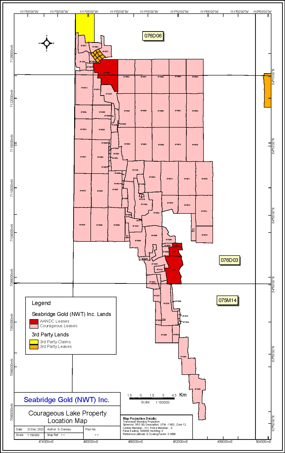
Source: Seabridge Gold, 2022
| Courageous Lake Project | Page 42 |
| Pre-feasibility Study and Preliminary Economic Assessment NI 43-101 Technical Report | January 5, 2024 |
| Figure 4-3: |
Claims Boundary and Proposed Resource Pit Locations (UTM Zone 12n) |
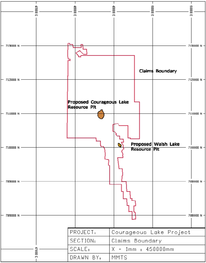
Source: MMTS, 2024
| Courageous Lake Project | Page 43 |
| Pre-feasibility Study and Preliminary Economic Assessment NI 43-101 Technical Report | January 5, 2024 |
The area of development on the Project
lies on both Territorial and Federal lands. The term “Territorial land” refers to lands where the administration and control
of public lands were transferred from the Federal Government to the Government of the Northwest Territories (GNWT) as defined in Chapter
3 (Section 3.1) of the Devolution Final Agreement. The Federal Government retained surface and subsurface ownership of legacy contaminated
sites and other lands that were listed in Schedule 7 of the Devolution Final Agreement. There are two areas that lie within the Courageous
Lake tenure area that remain under the jurisdiction/control of the Government of Canada: i) the former Tundra Mine site including the
airstrip, and ii) an area on the east side of the north arm of Courageous Lake where abandoned, historic exploration disturbances exist
which date back to the 1960s.
Thus, dispositions of public land
in the Courageous Lake area are managed pursuant to the Northwest Territories Lands Act (Territorial lands) and the Territorial Lands
Act (Federal lands). Seabridge NWT’s ownership of the Federal and Territorial mineral leases described in Section 4.3 provides the
necessary eligibility to obtain both non-exclusive and exclusive surface rights in the form of (short term) land use permits and (long
term) commercial surface leases or quarry lease, respectively.
Seabridge NWT currently holds title
to a small 4 ha surface lease (Lease 76D/3-6-6,Figure 4-4) that covers the Matthews Lake camp, and is valid until April 30, 2035. The
lease was first issued in 1994 by the Federal government, and following devolution in 2014 it is now administered by the Territorial government.
The surface lease was purchased from the previous owner by Seabridge in 2010. The lease has been renewed/re-issued several times since
1994 and authorizes the use of land for a “commercial camp”.
Seabridge NWT also has surface
rights in the form of land use permit MV2019C0025, issued by the MVLWB in 2020 pursuant to the Mackenzie Valley Land Use Regulations,
which authorizes various exploration activities until 2027. Seabridge has maintained land use permits for exploration at the Project since
2003. Plans are currently underway to renew this land use permit.
There is one other surface lease
holder within the immediate Courageous Lake area, associated with a fishing and hunting camp located on the north shore of the east arm
of Courageous Lake. The recreational camp has not been active for over 14 years and the lease holder has previously approached Seabridge
to purchase the lease and its associated facilities and equipment. This lease is located 3 km north of the proposed Courageous Lake Project.
To develop the Project, Valor Gold
will need to apply for one or more commercial surfaces lease(s) from the Territorial and possibly the Federal government, depending on
the extent of lands required for Project infrastructure. A commercial surface lease will grant the exclusive right to use the land for
commercial mining activities for a specified period and to make improvements upon the land. Specific terms and conditions will be included
in each lease. The surface lease(s) must be issued before mine construction or production commence pursuant to the Mining Regulations
under the Territorial Lands Act. An approved environmental assessment pursuant to the Mackenzie Valley Resource Management Act (MVRMA)
will be required before a surface lease will be issued.
The process will occur concurrently
with water licensing as elaborated in Section 20.2.
| Courageous Lake Project | Page 44 |
| Pre-feasibility Study and Preliminary Economic Assessment NI 43-101 Technical Report | January 5, 2024 |
A quarry lease will also be required
if Valor Gold requires long term rights to obtain sand and gravel resources from an area outside the boundary of their surface lease(s),
such as along the Courageous Lake winter spur road. The process to obtain a quarry lease is similar to the surface lease.
| Figure 4-4: |
Location of Surface Rights |
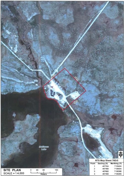
Source: NWT Department of Lands, 2015
| Courageous Lake Project | Page 45 |
| Pre-feasibility Study and Preliminary Economic Assessment NI 43-101 Technical Report | January 5, 2024 |
The use of water and deposit of waste
is regulated by the MVLWB through the issuance of water licenses in accordance with the Waters Act and Waters Regulations, and the MVRMA
and Mackenzie Valley Federal Areas Waters Regulations (MVFAWR). The applicable legislation depends on whether the water used or waste
discharged occurs on Federal or Territorial Lands (and waters). Type A licenses are issued for larger projects such as mines that use
more water or have a greater environmental impact. Type B licenses are issued for smaller projects with less impact on the environment,
such as exploration. The MVLWB issues both types of licenses; however, type A licenses require the approval of the Minister before they
become effective.
Seabridge NWT currently holds two
Type B water licenses (MV2019-L2-0011 and -0012) which authorize the short term use of water for exploration drilling on Territorial and
Federal lands respectively. The licenses were granted by the MVLWB in 2020 in accordance with the MVRMA and the above noted legislation
and are valid until March 2027.
In order to develop the Project,
the Company will need to apply for and obtain at least one, and possibly two Type A water licenses depending on the location of water
withdrawals and waste discharges associated with the Project. If project activities will take place in both Territorial and Federal areas,
two licenses will be required.
The process to obtain Type A water
licenses will be combined with the land use permit application process, and will require application(s), preliminary screening, consultation
with Indigenous Groups, review by Federal and GNWT departments, as applicable. An approved environmental assessment pursuant to the MVRMA
and conducted by the MVEIRB will be required, after which, a mandatory public hearing will be held by the MVLWB before a Type A license
can be issued. The Responsible Minister must approve a Type A license before it becomes effective.
Other water-related permits and fisheries
authorizations, as outlined in Section 20.2, will be required for the Project.
The nearest holder of water rights
is a water license for the use of water and deposit of waste for the Tundra Mine remediation project, issued to the Government of Canada,
Contaminants and Remediation Directorate.
| 4.6 | Royalties and Encumbrances |
In July 2002 Seabridge completed
the purchase of the Project from Newmont Canada Limited and Total Resources Canada Limited, which, at the time, consisted of 17 mining
leases covering 18,178 acres. Under the purchase agreement, Seabridge granted the Vendors a 2.0% NSR on the mining leases.
Upon acquiring the Project, Seabridge
assigned its right to its wholly owned subsidiary, Seabridge Gold (NWT). The obligations of Seabridge under the agreement, including the
payment of the royalty, is secured by a debenture under which the Vendors have been granted a security interest in the Courageous Lake
property. The purchase agreement includes an area of interest provision which makes any mineral tenures acquired by Seabridge NWT that
lie, in whole or in part, within 2 km of the exterior boundaries of the 17 mining leases sold by the Vendors subject to the 2% NSR.
| Courageous Lake Project | Page 46 |
| Pre-feasibility Study and Preliminary Economic Assessment NI 43-101 Technical Report | January 5, 2024 |
| 4.7 | Environmental Liabilities |
The Courageous Lake Closure and
Reclamation Plan identifies existing environmental liabilities and describes the activities required to achieve the closure goal of returning
the existing exploration area to viable and, wherever practicable, self-sustaining ecosystems that are compatible with a healthy environment
and human activities. This plan is a requirement of the existing Class A land use permit and Type B water licenses that authorize exploration
activities. The Closure and Reclamation Plan and associated liability estimate has been approved by the MVLWB.
Seabridge has undertaken exploration
activities in the Courageous Lake area since 2003, utilizing infrastructure (e.g. roads, airstrip, gravel pads, camp, other buildings)
that were established by previous owners/operators. Since 2003, Seabridge has drilled a total of 345 holes at 338 drill sites around the
property. Seabridge has progressively reclaimed all drill sites tested to date. To meet the requirements of permanent closure, Seabridge
has committed to undertake the following closure activities:
| ● | Removing buildings and infrastructure. |
| ● | Removing fixed and mobile equipment. |
| ● | Removing fuel storage facilities. |
| ● | Recontouring and stabilizing the sand and gravel borrow pit. |
| ● | Removing culverts and scarifying roads. |
| ● | Removing and/or disposing of all solid waste materials. |
To date, Seabridge has posted $45,000
security with the Governments of Canada and GNWT for future reclamation liabilities. The current land use permit and water licenses require
$320,000 additional security to be posted prior to undertaking further exploration. Upon completion of the spin-out, Valor Gold will assume
the obligations associated with future reclamation.
Further environmental considerations are discussed in Section
20.2.
| 4.8 | Permitting Considerations |
Refer to Section 20.3.
| 4.9 | Social License Considerations |
Refer to Section 20.4.
| Courageous Lake Project | Page 47 |
| Pre-feasibility Study and Preliminary Economic Assessment NI 43-101 Technical Report | January 5, 2024 |
| 5 |
ACCESSIBILITY, CLIMATE, LOCAL RESOURCES, INFRASTRUCTURE AND PHYSIOGRAPHY |
The overall topography of this area
is characterized by rolling hills ranging from 418 to 450 m in elevation above sea level. Typically, the maximum change in elevation is
only 30 m. Tundra type vegetation and small scrub brush dominate the areas between outcrops, particularly along the ridges in the southern
edge of the property. The northern part of the property is dominantly flat with little or no outcrop. Figure 5-1 is an oblique aerial
photograph providing an overview of the Courageous Lake deposit area.
| Figure 5-1: |
Aerial Photograph of Courageous Lake Property |
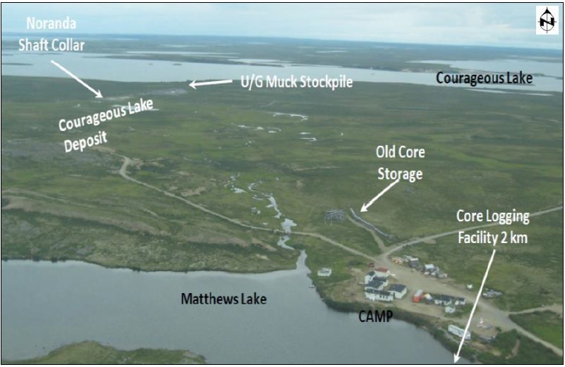
Source: Tetra Tech, 2012
| Courageous Lake Project | Page 48 |
| Pre-feasibility Study and Preliminary Economic Assessment NI 43-101 Technical Report | January 5, 2024 |
Year-round access is only possible
by air, either by helicopter or fixed-wing aircraft to the airstrip at Salmita (located 6 km to the south), or by fixed-wing aircraft
equipped with skis or floats to nearby lakes. Access is also possible in winter, over a 35 km winter road, which branches off the main
Tibbitt to Contwoyto winter road or by constructing an ice strip on Matthews Lake which could accommodate larger cargo aircraft. The winter
road is normally open from late January/early February until the end of March of each year, however depending on weather conditions it
could be open from as early as the beginning of January until mid April.
At nearly 64° north, temperatures
are often below freezing but between late May and August +20°C temperatures are common. Winter temperatures can be less than -50°C
over short periods and gale-force winds are not uncommon. Precipitation is minimal at an average of 290 mm annually. The climate does
not prevent the Project from operating year-round.
| 5.4 | Local Resources and Infrastructure |
There are no significant population
centers near the property, outside of Yellowknife. The nearest community of Wekweètì is located 140 km west of the Project
and had a population of 129 in 2016.
All access and transportation of
supplies need to be brought in either by air year-round or by road during the winter months.
Other than the rights described
in Sections 4.4 and 4.5, the Courageous Lake property is not subject to any other known surface encumbrances or mineral royalties. The
QP is unaware of any issues associated with sufficiency of surface rights for potential mining operations or other infrastructure-related
subjects (i.e. availability and sources of power, water, mining personnel, or potential tailing and waste disposal areas).
| Courageous Lake Project | Page 49 |
| Pre-feasibility Study and Preliminary Economic Assessment NI 43-101 Technical Report | January 5, 2024 |
Gold was first discovered in the
Courageous Lake area in the early 1940s by Dr. W. Brown, who was working for Territorial Exploration Ltd. The Tundra deposit was discovered
in 1944 and the Salmita deposit in 1947. The Geological Society of Canada carried out regional geological mapping in the area from 1944
to 1980. The Tundra Gold Mine went into production in 1964 and operated for about 4 years. During the 1990s, Royal Oak Mines Inc. briefly
reopened the Tundra Mine. Total reported production from the Tundra Mine was 122,000 oz of gold. During 1984 to 1989, the nearby Salmita
Mine produced 209,000 t averaging 27.2 g/t (183,000 oz). The author has done sufficient work to classify the verify this historical production
estimate.
| 6.2 | Noranda Exploration History |
The following section was taken
directly from RMI’s December 30, 2004 NI 43-101 report entitled “Technical Review of the Courageous Lake Property, Northwest
Territories, Canada” and remains largely unchanged.
Starting in 1976, Noranda Exploration Ltd.
began exploration activities in the Courageous Lake Volcanic Belt. Activities included geological reconnaissance, airborne electromagnetic
(AEM) and magnetic surveys, ground follow up, and claim staking.
In 1980, Noranda carried out a drilling
program to evaluate a frost-heaved felsic volcanic unit that was discovered by prospectors working for Noranda. This activity resulted
in the discovery of two new gold deposits: the FAT Zone, and the Carbonate Zone, which together form the Courageous Lake property.
Noranda and Getty Canadian Metals
partnered in 1982 (Tundra Joint Venture) to explore and develop the project that lead to completion of a 475 m exploration shaft. During
this time, Nornada acquired Battle Mountain Gold and consolidated precious metal interests in that unit, and Getty was acquired by Total
Energold.
Noranda initiated a limited drilling program
to evaluate rock units north of Matthews Lake. Detailed geophysics, geological mapping and extensive diamond drilling followed this initial
program leading to the discovery of two gold deposits: the Tundra Deposit (Main Zone) or FAT Deposit, and the Carbonate Zone.
From 1982 to 1987, Noranda continued
core drilling the property from the surface and also constructed a winter road to the property and began an environmental impact study.
In late 1987, Noranda made a decision to sink a vertical shaft to provide access for conducting an underground definition drilling program
and to be able to test gold grade continuity and tenor by drifting and raising on mineralized material grade shoots. This also allowed
Noranda to extract a bulk sample for metallurgical testing. In conjunction with the development of the shaft, surface core drilling, magnetic,
VLF, and horizontal loop electromagnetic (HLEM) surveys were also completed (Levett, 1998).
In 1987, Total Energold Corp. purchased
Getty and assumed their 49% interest in the Tundra Joint Venture.
| Courageous Lake Project | Page 50 |
| Pre-feasibility Study and Preliminary Economic Assessment NI 43-101 Technical Report | January 5, 2024 |
In February and March 1988, Thyssen
Mining mobilized equipment and personnel to the site. By July 1988, the surface infrastructure was in place and the exploration shaft
was collared. A three-compartment shaft was designed that provided:
| ● | two compartments for hoisting (2.02 x 2.02 m opening) |
| ● | a ventilation/manway compartment (2.02 x 1.75 m opening). |
The shaft was timbered from top
to bottom with horizontal cross sets placed vertically every 2.25 m and stub stations excavated at 45 m intervals to facilitate future
development. Geology was mapped at 1:50 scale in the shaft. The shaft sinking program was completed at 472.6 m in April of 1989.
Drifting on the target zone began
in May 1989 and was completed in November 1989 with a total development of 1,948.2 m. Both lateral drifts and sub-vertical raises were
developed and provided access to bulk sample locations and diamond drilling stations along the strike of the target zone. All drifts and
raises were excavated to nominal 3.0 x 3.0 m openings, totaling 64,044 tonnes of material. Development work averaged 9.2 m/d and contained
46,865 tonnes of waste and 17,179 tonnes of gold-bearing target zone ore material. Survey control was provided by a third-party contractor
using gyroscopic survey instruments linking the underground development with the surface mine grid. Geologic mapping, face channel sampling
and muck sampling were conducted during the development work.
Conners Drilling was contracted
for underground diamond core drilling. Vertically fanned NQ drill holes were collared on 50 m centers from underground drill stations
that were laid out on 50 m centers. Each underground drill station averaged six holes that were fanned out to provide reasonable data
spacing. 200 vertical meters of the mineralized zone were tested by the underground drill holes. The 50 m spaced drill stations tested
750-800 m of strike length. Additional horizontally fanned holes were drilled on 25 m centers to aid in the interpretation of the target
zone. Drilling was completed in November 1989 and totaled 27,459.25 m in 125 diamond core holes.
An estimated 17,000 t of material,
which was mined underground by Noranda, was hoisted and stockpiled on the surface. The resource model that is the subject of this report
has not removed the mined material from the block model. However, the QP notes that the tonnage is very insignificant, and tonnage still
exists on the property.
| 6.3 | Placer Dome Exploration Inc. |
In 1997, Placer Dome optioned the
property from Battle Mountain Gold with the concept of developing a bulk tonnage open pit deposit. To test that concept, Placer Dome completed
13,345 m of drilling focused on the Courageous Lake Deposit (formerly also referred to as the FAT deposit). In 2001, Battle Mountain Gold
merged with Newmont Gold Corp. (Newmont) and ownership of the Tundra Joint Venture was transferred to Newmont.
In 1998, Placer Dome Exploration Inc.
(PDX) preformed regional lithogeochemical sampling/prospecting and detailed mapping and channel sampling on the Courageous Lake property.
PDX completed a small core drilling/sampling program in order to verify Noranda’s previous work and to provide infill sample data.
Detailed mapping and structural analysis programs were run concurrently by PDX to familiarize their geologists with the property geology
and to help design a drilling plan. Most of the results of these studies were not available for this report.
| Courageous Lake Project | Page 51 |
| Pre-feasibility Study and Preliminary Economic Assessment NI 43-101 Technical Report | January 5, 2024 |
Also in 1998, Placer Dome conducted
a ground magnetic survey on the property to define the zone of mineralization and to detect other areas of possible mineralization. This
geophysical program allowed PDX to help distinguish the various rock types in the area and locate drill targets.
In 2002, Newmont offered the Courageous
Lake property for sale. In June 2002, Seabridge purchased the property from the Newmont-Total Tundra Joint Venture. Seabridge completed
drilling from 2003-2018 that continued evaluating the Courageous Lake and Walsh Lake deposits as well as other target areas within the
CLGB.
| Courageous Lake Project | Page 52 |
| Pre-feasibility Study and Preliminary Economic Assessment NI 43-101 Technical Report | January 5, 2024 |
| 7 | GEOLOGICAL SETTING AND MINERALIZATION |
The following section was provided
by Mr. James Freeman of Seabridge and is an excerpt from the previous technical report (TetraTech, 2012).
The Slave Structural Province covers
310,000 km2 in northeastern Northwest Territories and Nunavut. It is bounded to the north by Coronation Gulf and to the south
by Great Slave Lake, and wedged between the Bear Province to the west and the Churchill Province to the east. The predominantly Archean
rock types of the Slave Structural Province are granite plutons, broad platforms of sedimentary rock, and narrow volcanic belts. A map
of the regional geology is provided in Figure 7-1.
The Archean sedimentary and volcanic
supracrustal rocks that crop out in the Province were termed Yellowknife Supergroup by Henderson (1943). Rocks of this terrane are a product
of diverse tectonic origin, including rift and shelf assemblages, breakup-type tholeiitic basalt sequences, arc sequences, turbidites,
and late-tectonic clastic basins. Postulated to underlie the Yellowknife Supergroup, possibly separated by a regional décollement,
is significantly older sialic basement, termed the Central Slave Basement Complex (Bleeker et al., 1999) composed of a diorite to tonalite
gneiss.
| 7.2 | Courageous-MacKay Lake Greenstone Belt |
The Courageous-MacKay Lake Greenstone
Belt (CLGB) is a steeply east-dipping, north to northwest trending, homoclinal sequence. These sequences of metavolcanic and metasedimentary
rocks of the Yellowknife Supergroup form a composite pile 3 to 7 km wide and 70 km long. Regional mapping demonstrates that the sequences
are not overturned, and stratigraphic tops are to the east. The CLGB is bounded to the west by a sodic granite pluton referred to as the
Courageous Lake Batholith, and to the east by conformably overlying turbidite metasedimentary rocks (Moore, 1956). Dynamo-thermal regional
metamorphism within the CLGB has created mineral assemblages indicative of mid-greenschist facies metamorphic grade. Lower-amphibolite
facies metamorphic grade have been identified at the north and south limits of the CLGB. Four discrete deformational events are recorded
in these rocks.
Based on lithogeochemical analysis
and mapping done by Wells (1998) on the CLGB, the depositional environment is envisioned as one or more evolving island arcs. Early widespread
tholeiitic volcanism was followed by more restricted calc-alkaline eruptive centers, or islands. Bimodal tholeiitic/calc-alkaline volcanic
sequences of this type are common in Archean greenstone belts (Wells, 1998). Yellowknife Group sedimentary rocks, mainly greywackes and
siltstones, are interpreted to represent later stage proximal basin filling.
| Courageous Lake Project | Page 53 |
| Pre-feasibility Study and Preliminary Economic Assessment NI 43-101 Technical Report | January 5, 2024 |
| Figure 7-1: |
Regional Geology of the Courageous Lake Project |
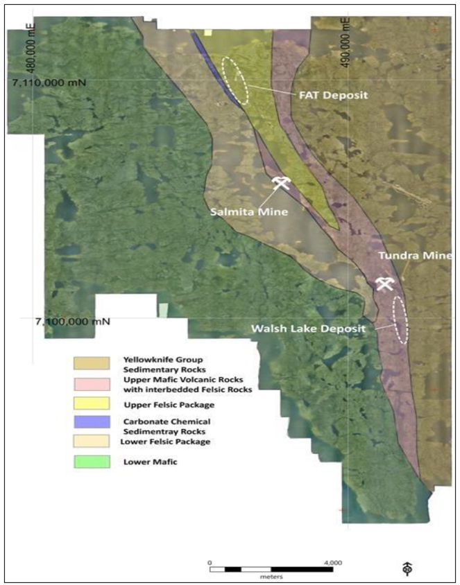
Source: Seabridge, 2024
| Courageous Lake Project | Page 54 |
| Pre-feasibility Study and Preliminary Economic Assessment NI 43-101 Technical Report | January 5, 2024 |
| 7.3 | Mathews Lake Greenstone Belt |
The Mathews Lake Greenstone Belt
(MLGB) is a steeply east-dipping, north to northwest trending, homoclinal sequence. These sequences of metavolcanic and metasedimentary
rocks of the Yellowknife Supergroup form a composite pile 3 to 7 km wide and 56 km long. Regional mapping demonstrates that the sequences
are not overturned, and stratigraphic tops are to the east. The MLGB is bounded to the west by a sodic granite pluton referred to as the
Courageous Lake Batholith, and to the east by conformably overlying turbidite metasedimentary rocks (Moore, 1956). Dynamo-thermal regional
metamorphism within the MLGB has created mineral assemblages indicative of mid-greenschist facies metamorphic grade. At the north and
south limits of the MLGB lower-amphibolite facies, metamorphic grade has been identified. Three discrete deformational events are recorded
in these rocks. Based on lithogeochemical analysis and mapping done by Wells (1998) on the MLGB, the depositional environment is envisioned
as one or more evolving island arcs. Early widespread tholeiitic volcanism was followed by more restricted calc-alkaline eruptive centers,
or islands. Bimodal tholeiitic/calc-alkaline volcanic sequences of this type are common in Archean greenstone belts (Wells, 1998). Yellowknife
Group sedimentary rocks, mainly greywacke and siltstone, are interpreted to represent later stage proximal basin filling.
The Walsh Lake Trend is a stratigraphic
break in the greenstone belt where clastic sedimentary rocks were deposited on mafic volcanic rocks. During deformation of the greenstone
belt several shear zones were formed on and near this contact. Gold-bearing fluids moved through these shear zones depositing quartz-arsenopyrite
and gold. There are several occurrences of these quartz vein zones along the MLGB, including the Walsh Lake zone.
| 7.4 | Stratigraphy – Courageous Lake and Walsh Lake |
The CLGB extends north-south for
70 km; it reaches a maximum thickness near Matthews Lake and narrows to a few tens of meters at both ends. The CLGB has been described
as consisting of two mafic to felsic cycles of volcanism. The basal cycle comprises mainly mafic to intermediate flow and pyroclastic
rocks, which have been largely assimilated by the Courageous Lake Batholith to the west. The basal cycle of basalt and andesite is capped
by a narrow band of rhyolite flow and tuff, which locally reaches a thickness of 60 m. The interpreted lower cycle contains numerous base
metal showings, including the DEB deposit (Dillon-Leitch, 1981; Ransom and Robb, 1983).
The second cycle contains mafic
to felsic flow and pyroclastic rocks. The felsic rocks are much more extensive in cycle 2, attaining a thickness of 1,800 m near Matthews
Lake, and a lateral extent of 25 to 30 km. They are composed of massive to porphyritic flow, tuff and coarse pyroclastic units. Felsic
volcanic rocks of cycle 2 are conformably overlain by the Yellowknife Group sedimentary rocks. The upper part of cycle 2 interfingers
with the overlying sedimentary rocks and is host to nearly all known gold occurrences in the belt (Ransom and Robb, 1983).
An alternative interpretation of the
volcanic stratigraphy is proposed based on work conducted by Seabridge. This interpretation calls for a single evolving volcanic succession
rather than two distinct cycles. This modification is based on the observations that the second cycle is preserved only in the central
part of the greenstone belt, and is intimately associated with dome-like rhyolite intrusions. On the margins of the CLGB, only a single
cycle of mafic to felsic eruptive rocks is present. Seabridge has developed an alternate interpretation in which the original basin was
filled with basaltic and andesitic lavas. As the basin evolved, rhyolitic volcanic rocks began to be deposited with the mafic rocks. There
are indications of bimodal volcanism
throughout the volcanic succession. In the central part of the basin, the volume of rhyolitic volcanic rocks swamp out the contribution
of mafic volcanic rocks, leading to a thick sequence of cycle 2 volcanic rocks. Only locally in the central part of the basin are mafic
rocks preserved once the rhyolitic volcanism began. As the rhyolitic volcanism waned up-section, sedimentation became more common until
it completely overtook volcanism, giving way to the turbidite sequence depicted in Figure 7-2.
| Courageous Lake Project | Page 55 |
| Pre-feasibility Study and Preliminary Economic Assessment NI 43-101 Technical Report | January 5, 2024 |
| Figure 7-2: |
Stratigraphic Sequence Models |
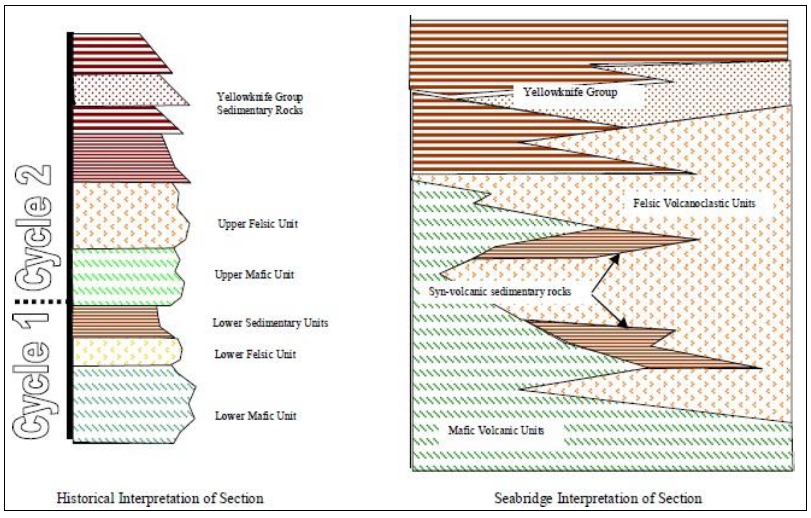
Source: Seabridge, 2023
According to Dillon-Leitch (1981),
CLGB supracrustal rocks have undergone three stages of metamorphism analogous to the history of the Yellowknife area reported by Ramsey
and Kamineni (1977). These events include:
| ● | early regional greenschist facies metamorphism associated with northwest-southeast compression |
| Courageous Lake Project | Page 56 |
| Pre-feasibility Study and Preliminary Economic Assessment NI 43-101 Technical Report | January 5, 2024 |
| ● | laterally discontinuous contact thermal metamorphic aureoles of greenschist and amphibolite facies associated
with granite intrusions |
| ● | late hydrothermally induced retrograde metamorphism in amphibolite facies rocks. |
All metamorphic events took place
under moderate confining pressures between 2 Kb and 4 Kb (Dillon-Leitch, 1981). The metasedimentary rocks exhibit the greatest variety
and continuity of metamorphic assemblages.
Pro-grade mineral assemblages in
and adjacent to the FAT deposit are the product of the early mid-greenschist facies grade metamorphic event. The constituent minerals
are chlorite + muscovite + biotite with minor almandine garnet porphyroblasts. The discontinuous and scattered distribution of the garnets
indicates compositional control rather than increasing pressure conditions. No mineralogical megascopic indication of a retrograde metamorphic
event has been noted in the FAT deposit area. The high-quality of preservation of the original rock textures in the FAT deposit and the
lack of a mineralogically distinct post-metamorphic hydrothermal event demonstrates that no regional metamorphic or hydrothermal events
have affected these rocks since the initial greenschist facies metamorphism.
Chlorite group minerals are common
pro-grade mineral assemblages associated with mid-greenschist regional metamorphism in the CLGB. In areas where garnet zone metamorphic
grade and higher was achieved, chlorite is rare and retrogressive pseudomorphs after almandine + corderite + biotite. Chlorite alteration
is noted in drilling as dark green, scaly masses on fractures and indistinct halos around zones of abundant garnets and biotite. Chlorite
is commonly associated with sericite + biotite alteration. Chlorite alteration in the FAT deposit is not associated with gold mineralization
and is mentioned here as a probable artifact of the metamorphic events that affected the mineral system.
Folds and cleavages formed during
four deformation phases have been identified during various generations of work in the CLGB. The distinctions between various phases are
based on field relationships and oriented thin sections by Dillon-Leitch (1981). As with metamorphic phases, the metasedimentary rocks
have more clearly preserved the structural history of the area.
The earliest phase of ductile deformation
is manifest as an east facing homocline. The structure is open, has an axial trace that trends north-south, and is flat lying to shallowly
south plunging. The interlimb distance of the structure is 2 km. It is postulated by Dillon-Leitch (1981) that the homocline formed in
response to diapiric upwelling of sodic granitoids along a preexisting north-south oriented, deep-seated fault on the western margin of
the CLGB. Synclines, along the eastern margin of the CLGB, were formed in Yellowknife Group sedimentary rocks. These features formed against
a static granite body during the diapiric rise of granite on the west side of the CLGB. Continued tilting of the homocline and east-west
compression developed major isoclinal folds in the sedimentary rocks. The axial traces of these folds parallel the trend of the CLGB,
except where folds deflect around the static granite plutons. Successive periods of regional, sub-horizontal compression created S1 and
S2 foliation fabrics and cleavages. The maximum strain over the belt is believed to coincide
with peak metamorphism and thermal doming during granite emplacement (Dillon-Leitch, 1981).
| Courageous Lake Project | Page 57 |
| Pre-feasibility Study and Preliminary Economic Assessment NI 43-101 Technical Report | January 5, 2024 |
Late-stage, brittle faulting in
the CLGB is generally restricted to two repeated orientations: north-northwest and east-northeast. In the deposit area north-northwest
faults are dextral and have a right-lateral sense of movement. The east-northeast faults exhibit sinistral rotation with left-lateral
displacement. Orientations and sense of movement of the faults indicate they are coeval with emplacement of gabbro dikes, and Proterozoic
in age (Zhang, 1998).
| 7.7 | Petrography and Lithogeochemistry |
Various generations of petrographic
and lithogeochemical analyses have been done on the rock units of the FAT deposit and the various igneous lithologies of the CLGB. The
objectives of these investigations were:
| ● | characterize the volcanic and intrusive rock lithologies |
| ● | explain the genesis of source magmas |
| ● | determine the controls on gold mineralization. |
Geochemical signatures from sample
suites of the CLGB metavolcanic rocks indicate a typical tholeiitic to calc-alkaline, Archean greenstone volcanic succession. Mafic volcanic
rocks are metaluminous, sub-alkaline, of tholeiitic affinity and basalt to basaltic-andesite in composition. Felsic volcanic rocks are
dacite to rhyolite in composition with chemical affinity to subduction related magmas (Wells, 1998).
All previous work has reiterated
the strong associations between alkali depletion, sericite (K-metasomatic replacement of Ca, Na) alteration and silica alteration, with
gold concentrations. Strataform quartz introduction and secondary silica alteration are shown to have good correlation with As, Au, Ag
and W enrichment. TiO2 vs. Zr scatterplots done by Wells (1998) and Madeisky (1999) on full suites of FAT host lithologies suggest that
gold is not concentrated in any unique lithology.
| 7.8.1 | Courageous Lake Deposit Mineralization |
Since its discovery, several common
points have been used to describe the FAT deposit, including:
| ● | a series of gold zones concentrated in long and narrow bands |
| ● | the deposit is hosted by metasedimentary and metavolcanic
rocks |
| ● | gold concentrations are associated with the introduction
of silica, muscovite, and sulphide minerals. |
Several early operators (e.g.
Giant Yellowknife Mines and Noranda) in the CLGB utilized gold deposit models based on metamorphogenic lode gold concepts developed
in the Superior Province to describe the FAT deposit (Ransom and Robb, 1985; Kemp, 1987). Placer Dome demonstrated that the FAT
deposit did not form through metamorphic processes (Lau, 1990; Wells, 1998). Seabridge now favours an epithermal-like genesis for
the FAT deposit.
The FAT deposit is located between
the north shore of Matthews Lake and the south shore of Courageous Lake. It is made up of at least 13 discrete, steep east-dipping, elongate
lenticular zones that vary in thickness from 20 to 125 m wide. The continuity of these 13 zones has been demonstrated to be at least 1,900
m long (between UTM 7,108,700N and 7,110,600N), 800 m wide (between UTM 486,000E and 486,800E) and, although open at depth, at least 1,200
m deep. The 13 mineral zones are shown in a northwesterly perspective view, in Figure 7-3.
| Courageous Lake Project | Page 58 |
| Pre-feasibility Study and Preliminary Economic Assessment NI 43-101 Technical Report | January 5, 2024 |
| Figure 7-3: |
Perspective View of the FAT Mineral Zones |
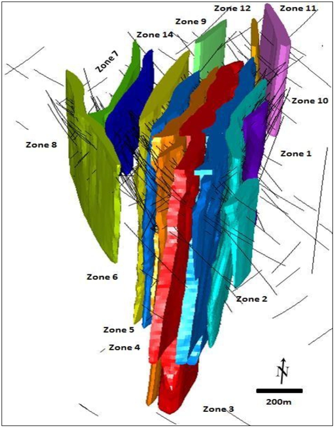
Source: Tetra Tech, 2012
| Courageous Lake Project | Page 59 |
| Pre-feasibility Study and Preliminary Economic Assessment NI 43-101 Technical Report | January 5, 2024 |
| 7.8.2 | Walsh Lake Mineralization |
The Walsh Lake target is 10 km
south of the FAT deposit, adjacent and south of the historical Tundra Gold Mine that was abandoned in 1999. The north part of this target
area is connected by a road network that links to the FAT deposit. Walsh Lake is interpreted to be a series of structural zones, parts
of which are on strike with the deposits exploited in the Tundra Gold Mine.
The Walsh Lake target area stretches
one and a half kilometer south from the former mine. This area has undergone several generations of exploration, including some limited
past drilling campaigns showing these gold occurrences were located near a regional stratigraphic contact, which could provide significant
strike potential. Gold-bearing quartz veins are hosted in sheared rocks near the contact between metamorphosed graywacke and mafic volcanic
rocks. The metagraywacke units are fine to coarse sand size material with well preserved, laterally discontinuous, fining upward sequence
of graded beds. This turbidite section is distinguished by the absence of volcanic and chemical sedimentary rocks intercalated in the
Bouma beds. Metamorphosed mafic volcanic rocks are black to green-black, dense, fine-grained, and typically show fragmental textures.
These rocks are principally made up of fine hornblende and plagioclase laths, with localized irregular and fractured dark garnet crystals.
Drilling on the Walsh Lake contact
zone consistently encounters silica alteration with gold-bearing intervals up to 20 m above the contact in siltstone and up to 60 m below
the contact in mafic volcanic rocks interbedded with siltstone or felsic volcanic rocks. Gold is concentrated in arsenopyrite-bearing
silica-altered sheared rocks containing abundant quartz veins, with true widths from one to 12 m. The shearing is almost parallel with
bedding. This deformation event is associated with the tilting and regional metamorphism and focused along rheological changes in the
stratigraphy.
| 7.9 | Lithology – Courageous Lake |
The rocks of the FAT deposit have been metamorphosed,
however in the following discussion the prefix “meta” has been omitted from their lithologic description for convenience of
the reader.
| 7.10 | Volcanic Rocks – Courageous Lake |
The volcanic rocks of the CLGB
represent a tholeiitic to calc-alkaline suite of volcanic rocks, common to many Archean greenstone belts of the world. U-Pb and Rb-Sr
age determinations of a general suite of CLGB volcanic lithologies give an age of 2.66 Ga (Dillon-Leitch, 1981).
Mafic volcanic rocks are classified
as basalt and basaltic-andesite (Moore, 1956). This unit crops out along the western margin of the greenstone belt as low relief ridges.
The flows are holocrystalline, massive, fine-grained and medium-to-dark green in color. They are commonly amygdaloidal and pillowed indicating
a shallow, subaqueous, depositional environment. No mafic volcanic rocks are known in the FAT deposit.
Felsic volcanic rocks and their intrusive
equivalents in the CLGB were derived from peraluminous, sub-alkaline magmas of calc-alkaline affinity (Wells, 1998). The rocks are dacite
to rhyolite and range in color from pale grey to light green. Lithic-bearing tuff, ash and agglomerate are the principal rock textures.
These felsic volcanic lithologies are the predominant host to the FAT deposit.
| Courageous Lake Project | Page 60 |
| Pre-feasibility Study and Preliminary Economic Assessment NI 43-101 Technical Report | January 5, 2024 |
The felsic volcanic rocks are the
best-described units in the area because of their association in the FAT gold deposit. In general, these rocks are a package of fine-grained
pyroclastic units that regionally form a relatively thick but laterally restrictive pile. Compositionally these rocks seem to vary little,
but textural variation is diverse. The most common variety of felsic volcanic rock is lapilli-tuff, generally composed of 30% juvenile
phyric fragments in a phyric groundmass as shown in Figure 7-4. Note that the scale bar in Figure 7-4 is 7 cm long. This rock shows ubiquitous
welding and compaction layering. Lithic-tuff is less common and generally contains 10% cognate lithic clasts of porphyritic rhyolite in
a phyric groundmass. Crystal-tuff units are uncommon and seem to be limited in lateral and vertical extent. These rocks are typically
very fine-grained with a trace to 20% β-quartz crystal inclusions and rare accidental lithic inclusions. The second most common pyroclastic
lithology is ash tuff. This unit is composed of 60-80% very fine phyric fragments with minor amounts of pumice fragments of lapilli size.
| Figure 7-4: |
Lapilli-tuff Unit in Outcrop |
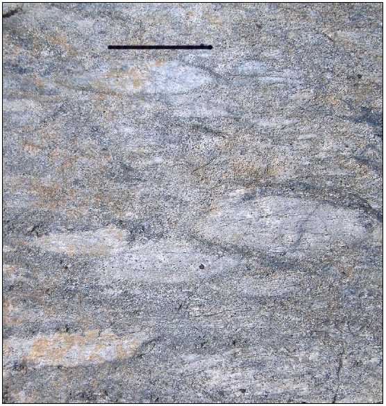
Source: Tetra Tech, 2012
| Courageous Lake Project | Page 61 |
| Pre-feasibility Study and Preliminary Economic Assessment NI 43-101 Technical Report | January 5, 2024 |
Within the felsic volcanic rocks
of the FAT deposit are abundant lens-shaped, epiclastic intercalations. Whole-rock analyses by Wells (1998), and others, have shown many
of the sedimentary rocks are derived from a tuffaceous source. They are generally light brown to grey-black in color. Flame structures,
graded bedding, load casts, and slump features are common in these rock units, which correspond to an inter-volcanic low-energy depositional
environment. Metamorphic grade is low and primary sedimentary structures are preserved. The lithologies are tuffaceous greywacke, thinly
laminated siltstone and fine-grained arkosic sandstone. The coarser clastic units vary from thickly bedded to massive and generally show
graded bedding. The coarser clastic rocks can form massive beds up to 15 m thick. Fine-grained siltstone is thinly laminated and seldom
exceeds 7 m in thickness.
Intruding and post-dating all rocks
groups are Proterozoic gabbro dikes. Selected dike samples in the province have yielded ages of 2.0 Ga (Dillon-Leitch, 1981). In the FAT
deposit vicinity, a prominent east-northeast dike offsets mineral domains of the FAT deposit by 25 m. Narrow gabbro dikes are encountered
elsewhere in the FAT resource as north-northwest trending features; most are not exposed at the surface. These intrusive rocks have no
economic importance.
| 7.13 | Hydrothermal Alteration |
The mineral domains of the FAT
deposit are defined by a discrete suite of hydrothermal alteration assemblages. The lateral continuity and stratigraphic thickness of
the hydrothermal system indicates that the FAT deposit was robust in volume and duration. Alteration styles are of varying intensity and
can exist independently and in combination.
The predominant hydrothermal alteration
minerals in the FAT deposit are illite group sheet silicates, referred to as a single mineral, “sericite”. Sericite alteration
is identified wherever fine-grained, white-grey, aligned mica (muscovite/paragonite) is encountered. This alteration style is best developed
in the felsic volcanic rock units, due to the original glassy nature of these rocks. It is recognized that original devitrification of
the felsic volcanic rock followed by greenschist metamorphism is likely to create a mineral assemblage that mimics sericite alteration
associated with hydrothermal fluids. In the absence of a definitive feature to discriminate the source of sericite, Seabridge has followed
the convention of previous workers and catalogued all sericite occurrences as alteration. Figure 7-5 is a typical example of sericitic
alteration at Courageous Lake. Note that the yellow tape measure is graduated in centimeters. This is a sample of drill core from the
FAT deposit.
| Courageous Lake Project | Page 62 |
| Pre-feasibility Study and Preliminary Economic Assessment NI 43-101 Technical Report | January 5, 2024 |
| Figure 7-5: |
Typical Sericite Alteration |
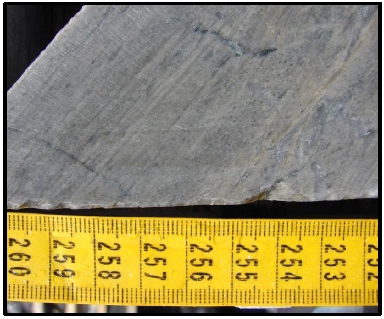
Source: Tetra Tech, 2012
Intensity of sericite alteration
varies widely in the FAT deposit. In most cases, it is associated with other alteration styles but can be found independently. All the
recognized sulphide minerals in the FAT deposit can be found in sericite alteration. The presence of sericite alteration is a necessary
component of gold occurrences, but the intensity of sericite alteration alone is not diagnostic of gold mineralization. This association
of sericite alteration and gold suggests that mineralized material forming fluids in the FAT mineral deposit are in part K-bearing and
capable of leaching Ca and Na.
Silicic alteration of varying intensity
is ubiquitous throughout the defined mineralized material domains and much less common between mineralized material domains in felsic
volcanic rock of the FAT deposit. It is texturally retentive in volcanic rocks, only rarely overprinting and destroying primary pyroclastic
textures. Silica flooding of groundmass material in volcanic rock is microcrystalline, blue-grey in color and closely related to strataform
quartz zones. The most intense zones of silicic alteration are not generally indicative of higher gold concentrations. This gold-poor
silica alteration may be another expression of the original devitrification of the glassy volcanic pile that hosts the FAT deposit.
Two distinct varieties of quartz
have been identified in the FAT deposit mineralized material domains (Figure 7-6). The predominant variety is blue-grey, cryptocrystalline
quartz as thin, sulphide-bearing strataform anastomosing veinlets and strataform lenses. Less common is medium-grain crystalline, white-grey
quartz zones, often containing abundant iron carbonate minerals (predominantly ankerite) and calcite at the margins of these quartz zones.
The white-grey quartz zones and veins typically crosscut the blue-grey quartz in the mineralized material domains. White-grey, quartz-ankerite-calcite
veins up to 0.5 m-wide are common between mineralized material domains. These veins cut perpendicular to the original depositional layering
preserved in the volcanic rocks. The two types of quartz alteration are shown in the drill core photograph in Figure 7-6.
| Courageous Lake Project | Page 63 |
| Pre-feasibility Study and Preliminary Economic Assessment NI 43-101 Technical Report | January 5, 2024 |
| Figure 7-6: | Types
of Quartz Alteration |
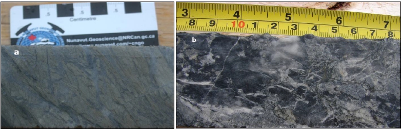
Source: TetraTech,
2012
Much
of the technical literature for the FAT deposit uses “vein” to describe the silica alteration in the mineralized material
domains. Textures in these zones of strataform silica alteration are more consistent with pervasive inundation of silica-bearing fluids
into the rock, rather than a fracture-filling. The nature of the fluid responsible for the silica alteration is a silica saturated and
metal-bearing hydrothermal fluid. Textural evidence indicates the fluid invaded the rock at pressures that for the most part did not
exceed the lithostatic lode in the volcanic pile.
Carbonate
alteration is a ubiquitous constituent affecting the rocks hosting the FAT deposit. Whether the source of abundant carbonate is from
seawater or as a product of cation liberation during alkali leaching is unknown. Carbonate as calcite, ankerite, and siderite are common
accessory minerals with white, medium crystalline quartz zones and veins. Calcite is common as infill of late-stage fractures and small
shear zones and is found in minor amounts in the matrix of most rocks in the FAT deposit. Carbonate alteration is a major and widespread
component of the assemblages of the FAT deposit, but is not believed to be an important process in introduction of gold mineralization
in the rocks of the FAT deposit.
The
most pervasive zones of carbonate alteration are found in the stratigraphically older mineralized material domains of the FAT deposit.
Stratigraphically below, and as part of Zone 8, are breccias derived from clastic debris flows with a matrix of calcite. In addition,
sucrossic calcite is found replacing lapilli clasts in volcanic rocks of Zone 8. Younger mineralized material domains (Zones 1 to 5)
contain similar abundances of calcite fracture infill, quartz/carbonate veins and strataform masses, but fine crystalline calcite impregnating
matrix material is much reduced and spottier in nature. Throughout the deposit ankerite is a common mineral associated with white-grey
quartz zones as subhedral, irregular masses embayed at the boundaries of these quartz zones.
| Courageous Lake Project | Page 64 |
| Pre-feasibility Study and Preliminary Economic Assessment NI 43-101 Technical Report | January 5, 2024 |
Potassic
alteration is restricted to the external margins of gabbro intrusions within the FAT deposit and is not associated with gold concentrations.
This alteration type is manifested in microvein filling and vein salvages or patchy zones as distinctive pink orthoclase, biotite, quartz
and pyrrhotite. Potassic alteration is intense and distinct within a few meters of a gabbro intrusion but not recognized elsewhere in
the FAT deposit.
Sulphide
mineralogy in the FAT deposit is relatively simple and consists of pyrite, pyrrhotite, arsenopyrite, sphalerite and chalcopyrite in decreasing
order of abundance. All of these minerals can be found in the ore domains but only arsenopyrite has a consistent correlative relationship
to gold concentrations.
Pyrite
is present throughout the volcanic pile ranging in abundance from a trace to 5%. It is disseminated in the rock or along fractures and
microveinlets. The pyrite habit is euhedral to subhedral, ranging in size from 0.5 to 4.0 mm.
Pyrrhotite
has a more restrictive distribution but can be very abundant in sedimentary rocks intercalated with the volcanic pile. Concentrations
of pyrrhotite range from a trace to 8%. It is found in fractures and microveins in the volcanic rocks and as semi-massive lenses in sedimentary
rocks. An anhedral habit or clotty composite crystals are typical in the size range of 0.5 to 3.0 mm.
Arsenopyrite
is recognized in three distinct habits and it is the best guide to the occurrence of gold. Concentrations of arsenopyrite can range from
a trace to 10% but typically, where present, it is less than 1% of the rock. Arsenopyrite is found as:
| ● | acicular crystals
disseminated or as partial to full replacement of lapilli fragments, the discrete needle-like crystals
are 0.5 to 2.5 mm long |
| ● | anhedral disseminated
clots of arsenopyrite is in the size range of 0.5 to 2.0 mm |
| ● | euhedral arsenopyrite
in fractures, from 1.0 to 5.0 mm across. |
Both
the fine anhedral and acicular arsenopyrite are associated with gold concentrations but the acicular variety seems to have the clearest
association in much of the deposit. Coarse arsenopyrite is not common and seems to have little association with gold.
Sphalerite
and chalcopyrite are trace components of the mineral system. They are typically euhedral to subhedral discrete minerals ranging in size
from 0.3 to 1.5 mm. There most common occurrence is at the margin of and within the chill margin of the younger gabbro intrusions.
| Courageous Lake Project | Page 65 |
| Pre-feasibility Study and Preliminary Economic Assessment NI 43-101 Technical Report | January 5, 2024 |
The
Courageous Lake deposit is a stratiform series of near-vertical, elongate lenticular mineralized domains hosted in Archean tuffaceous
clastic rocks and ash-flow tuff. Gold mineralization is interpreted to be a product of an episodic, epithermal-like, submarine and subaerial,
hydrothermal system. Regional deformation has imparted minor metamorphic mineralogical and geometric modifications to the deposit. The
hydrothermal system is interpreted to have formed within an emerging, peraluminous, calc-alkaline rhyolite to rhyodacite volcanic edifice.
Although there is no strict lithological control to the gold distribution in the deposits, each of the identified domains has a consistent
stratigraphic architecture that distinguishes them. Gold concentrations are associated with:
| ● | intense
(>20%) alkali depletion of the volcanic rocks |
| ● | K-metasomatism
manifested as sericitic alteration |
| ● | strataform
quartz zones accompanied by broad, variably intense silicic alteration |
| ● | concentrations
of acicular arsenopyrite crystals. |
The
Walsh Lake zone is contained in quartz vein and silicic alteration within and surrounding shears. Mineralized material mineralogy is
dominated by arsenopyrite and free gold. This style of orogenic gold deposit is common in Archean greenstone belts.
| Courageous Lake Project | Page 66 |
| Pre-feasibility Study and Preliminary Economic Assessment NI 43-101 Technical Report | January 5, 2024 |
During
2003, Seabridge designed and executed a work program on the Courageous Lake property with the goal of evaluating and prioritizing potential
gold targets. Four targets were developed, South FAT Extension (currently part of the Courageous Lake Deposit), Olsen Lake Target, Walsh
Lake Target and Salmita Mine Target. These targets were selected as the highest probability to develop new resources for the project.
In
2004, drill testing of selected priority targets was undertaken by Seabridge. The program was conceived in 2 stages, initial testing
for stratiform gold concentrations similar to the FAT Deposit and sectional drilling of potential resource expiations. The initial program
intended to test three target areas, Olsen Lake, Walsh Lake and the South FAT Extension. Ground conditions precluded a test of the Walsh
Lake target, but the other targets were tested. Results from the initial stage of the program lead the company to initiate sectional
drilling on the South FAT Extension.
The
South FAT Extension was a projection of the previous resource model where little work had been completed. Surface and initial drilling
results indicated that 300 m of strike could be added to the Courageous Lake Deposit with the completion of sectional drilling. The second
stage of the 2004 program completed the sectional drilling on 50 m section lines across these 300 m of strike.
Exploration since
2005 has been exclusively drilling programs by Seabridge, as discussed in the following section.
Valor Gold has not completed any exploration
on the Courageous Lake property.
| Courageous Lake Project | Page 67 |
| Pre-feasibility Study and Preliminary Economic Assessment NI 43-101 Technical Report | January 5, 2024 |
| 10.1 | Courageous
Lake Property Drilling |
Table
10-1 summarizes Courageous Lake Property drilling by deposit and company The total drill meterage shown in Table 10-1 includes overlaps
associated with wedge holes that were completed by Noranda and Seabridge. Valor Gold has not completed any drilling on the Courageous
Lake Property. Not all of the meterage shown in Table 10-1 was assayed for gold. This is particularly true for the Noranda data. 5,000
m of un-assayed Noranda core was assayed by Seabridge.
The
table provided at the beginning of Section 14 details the drilling data that was assayed for gold, which are located within the limits
of the block model and that were used to estimate mineral resources.
| Table 10-1: | Summary
of Courageous Lake Property Drilling |
| Deposit |
Company |
Number
of Drill
holes |
Total
Depth
(m) |
Length
Assayed
(m) |
Total
% Assayed
(m) |
| Courageous
Lake |
Placer
Dome |
351 |
93,027 |
42,224 |
45% |
| Noranda |
96 |
22,684 |
22,110 |
97% |
| Seabridge |
255 |
77,251 |
72,633 |
94% |
| Walsh
Lake |
Noranda |
51 |
10,493 |
2,628 |
25% |
| Seabridge |
54 |
17,792 |
17,475 |
98% |
| Salmita |
Pre-Noranda |
38 |
5,938 |
447 |
8% |
| Noranda |
218 |
48,379 |
10,629 |
22% |
| Seabridge |
36 |
8,522 |
8,311 |
98% |
| Total |
1,099 |
284,086 |
176,456 |
62% |
| 10.1.1 | Pre-2010
Drilling Programs – Courageous Lake Property |
The
following is an excerpt from TetraTech (2012):
Prior
to 1982, Noranda explored the Courageous Lake properties in search of base metal massive sulphide deposits. As a result of that program,
a large number of holes were drilled in the area, most of which were unrelated to the Courageous Lake gold system. In 1982, Noranda initiated
exploration in the region for gold. Between 1982 and 1985 a large number of targets were tested with small helicopter supported drill
rigs. Based on these programs, a total of 11,239 meters of drilling was completed on the Tundra Main Zone, carbonate zone and surrounding
area.
In
1986, Noranda contracted 39,030 meters of NQ core drilling on the Tundra and carbonate zones in 76 drill holes. This program was the
initial delineation drilling of the targets and led to several internal resource estimations. In total, Noranda completed 317 drill holes
for a total of 85,276 meters in both surface and underground drilling campaigns.
| Courageous Lake Project | Page 68 |
| Pre-feasibility Study and Preliminary Economic Assessment NI 43-101 Technical Report | January 5, 2024 |
Placer
Dome Exploration acquired an option to evaluate the Courageous Lake project and conducted drilling operations in the fall of 1997 and
summer 1998. Placer used two NQ diamond drill rigs to provide detailed information on the continuity of the Tundra Main Zone and to confirm
the carbonate zone. This program concentrated on completing drill hole fences consisting of five holes per fence on strategically selected
east-west sections spaced at 25 to 50 meters. The total diamond drilling completed by Placer was 22,684 meters in 96 drill holes.
| 10.2 | Seabridge
Drilling Programs – Courageous Lake Property |
In
the summer of 2004, Seabridge Gold drilled 23 surface core holes totaling 7,940.7 m. The majority of these holes were drilled near the
southern end of the FAT Zone in order to extend the strike length of the deposit.
During
the 2005 and 2006 field seasons Seabridge gold drilled 39 diamond core holes totaling 15,428 m. The drilling was completed by Connors
Drilling (Prince Rupert, BC) using helicopter supported Boyles 25 S drill rigs. Most of the core that was recovered was NQ2 diameter
(50.7 mm) using 3.048 m core barrels. The core collected from these drill holes was systematically logged, sawn, and shipped to ACME
Labs in Yellowknife, NWT and Vancouver, BC for sample preparation and fire assay.
Pre-2010
drill hole collars were translated into NAD83 Canada (MSL) by LiDAR Services International Inc. The 2010 through 2012 drill hole collar
locations were surveyed using a high-precision Trimble DGPS unit, which converted the collar coordinates to NAD83 (MSL). Prior to 2010,
a local mine grid coordinate system was used at Courageous Lake.
In
2010, Seabridge drilled 49 diamond core holes totalling 22,400 m. In 2011, 56 diamond drill holes were drilled for a total of 17,137
m and in 2012 and additional 13 DDHs were drilled for a total of 6,019 m.
Drilling
since 2012 at courageous Lake Deposit consisted of 180 holes for a total of 53,873 m.
The
diamond drilling since 2010 was completed by Hy-Tech Drilling Ltd. (Smithers, BC) using three Tech-5000 Fly Rigs with NQ tools. Drilling
conditions were generally excellent and there was no need to reduce the bore hole diameter. A 3 m long core barrel and wireline was used
to retrieve the core. An additional 10 shallow geotechnical core holes were also drilling under the direction of Seabridge’s geotechnical
contractor, EBA.
The
drill holes were surveyed down-the-hole using a Reflex tool. The surveys were collected at 75 m spacings down-the-hole for exploration
holes and 50 m for geotechnical holes.
The
drill hole samples were logged and sampled on site at Seabridge’s core logging facilities. Golder had geologic representatives on site
during the 2010 drilling campaign to conduct detailed geotechnical logging of the drill core.
The
core samples were routinely flown from the project site by charted fixed-wing aircraft to Yellowknife, 240 km to the south. The samples
were prepared at ACME’s facility in Yellowknife; the pulps were then transported by air to ACME’s assay laboratory in Vancouver, BC.
| Courageous Lake Project | Page 69 |
| Pre-feasibility Study and Preliminary Economic Assessment NI 43-101 Technical Report | January 5, 2024 |
Figure
10-1 is a plan view of the drill holes by drill campaign at Courageous Lake. Figure 10-2 is a N-S sectional view of the drilling at the
center of the deposit, showing the location and extent of the historic and underground drilling. The resource pit and geologic shapes
used in modelling are also included in the section for reference.
| Figure 10-1: | Drill
Collar Location Plan – Courageous Lake Deposit |
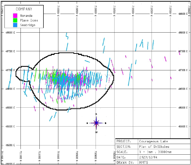
Source:
MMTS, 2023
| Courageous Lake Project | Page 70 |
| Pre-feasibility Study and Preliminary Economic Assessment NI 43-101 Technical Report | January 5, 2024 |
| Figure 10-2: | Sectional
View of Courageous Lake Drilling by Drill Campaign |
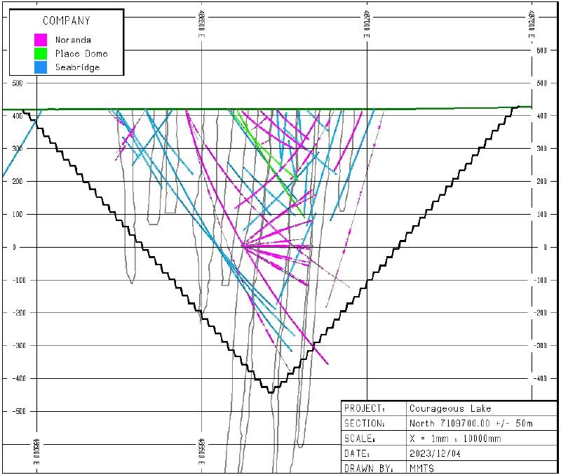
Source:
MMTS, 2023
| 10.3 | Seabridge
Drilling Programs - Walsh Lake Deposit |
Drilling
at Walsh Lake by Seabridge was all done in 2012 and 2013. Figure 10-3 is a plan map of the drilling. Drill holes shown in red were not
used for Resource Estimate both because they were outside the mineralized zone and because there were large portions of the hole which
were not assayed.
| Courageous Lake Project | Page 71 |
| Pre-feasibility Study and Preliminary Economic Assessment NI 43-101 Technical Report | January 5, 2024 |
A
total of 16,643 m of diamond core drilling was completed in 51 drill holes in the Walsh Lake area. Drilling was conducted by Hy-Tech
Drilling from Smithers, BC, utilizing a proprietary helicopter-portable drill and NQ2 drill tools. Details of the drilling are the same
as those for Courageous Lake, as outlined in Section 10.2.
For
a summary of the drill holes used for the Resource Estimate, see Section 14.
| Figure 10-3: | Drill
Collar Location Plan – Walsh Lake |
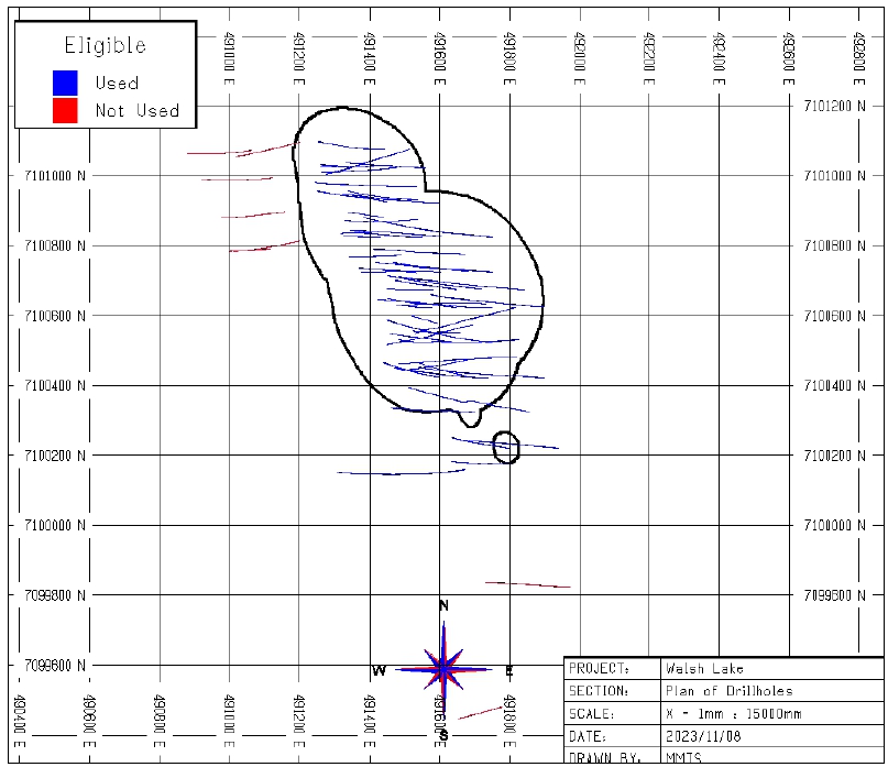
Source:
MMTS, 2023
| Courageous Lake Project | Page 72 |
| Pre-feasibility Study and Preliminary Economic Assessment NI 43-101 Technical Report | January 5, 2024 |
| 11 | SAMPLE
PREPARATION, ANALYSES, AND SECURITY |
Section
11 contains a comprehensive review of the QA/QC assay data of Courageous Lake and Walsh Lake with respect to Au, focusing on samples
from drill holes used for resource modelling.
Sections
11.2 to 11.6 contain selected extracts of previous reports on Courageous Lake as follows:
| ● | Technical
Review of the Courageous Lake Property, Northwest Territories, Canada RMI December 30, 2004. |
| ● | Updated
Mineral Resource Estimate Courageous Lake Project, Northwest Territories, Canada. RMI February
22, 2007. |
| ● | 2012
NI 43-101-compliant Pre-feasibility Study by Tetra Tech Wardrop et al. 2012. |
Sections
11.2 to 11.6 include sampling, preparation, analysis, QA/QC protocols descriptions for both the Courageous Lake and Walsh Lake projects.
Given the similarities and proximity of the two deposits and since Seabridge was the operator for both for the last 20 years, the procedures,
assay methods, and QA/QC insertion rates are largely comparable. Seabridge protocols employed at Walsh Lake in 2012-2013 are stated separately.
In
Section 11.7, MMTS reviews all available QA/QC data that are relevant to the Courageous Lake Resource Estimate. The tabled counts and
rates can vary compared to numbers in extracts from previous reports due to a lack of data availability from Seabridge’s internal
assay database but are overall comparable.
In
Section 11.12, MMTS reviews all available QA/QC data that are relevant to the Walsh Lake Resource Estimate, as per the sample assay results
for all considered drill holes shown in Section 10.
| 11.2 | Historical
Sampling Courageous Lake |
The
following paragraphs were taken from the 2004 technical review of Courageous Lake completed by RMI, with minor textural modifications
(RMI, 2004).
Noranda
established and documented sampling protocols for both their drill core sampling and underground face sampling programs. During the critical
delineation drilling program, Barringer Laboratories set up and operated a sample analysis facility on the Project site.
Drill
core samples were taken at geologic breaks and were designed so that sample lengths did not exceed 1.5 m. Most of their sample lengths
were generally 1 m long. The core was delivered to technicians that sawed the core for sampling and cross-validated the intervals with
the geologic logs.
| Courageous Lake Project | Page 73 |
| Pre-feasibility Study and Preliminary Economic Assessment NI 43-101 Technical Report | January 5, 2024 |
When
discrepancies between the geologic log intervals and the core splitter intervals were encountered, the sample was discarded, and a quarter
split of the core was made to reflect the geologic sample logs. Samples collected by the geologic team on site were delivered daily to
the Barringer’s on-site facility, where they were catalogued and compared with Noranda’s transmittal forms.
The
1982-1986 Noranda samples were air-dried and the entire sample was processed through a jaw crusher and cone crusher so that 100% of the
material passed through a 10 mesh screen. The sample was then homogenized and split into a 500 g sub-sample that was then reduced to
minus 150 mesh in a ring pulverizer. This pulp was then homogenized and split into several 15-30 g charges. Pulp samples were analyzed
by fire assay with an atomic absorption finish. Samples that were identified with abundant arsenopyrite and had an initial fire assay
value >6.0 g/mt Au were re-fired with a gravimetric finish.
Noranda’s
sampling protocols ask for a duplicate check analysis to be completed for every 10th sample. In addition, a sample standard
was inserted as the 20th sample in every sequence of samples. Blind blank samples were provided to the lab facility for every
50th sample. These blind samples were collected from homogenous barren material on site. Duplicate analyses were preformed
a Neutron Activation Laboratories on randomly selected samples for every sequence of 50 samples. Excess pulp samples and reject material
were stored on site but have since been discarded.
| 11.2.2 | Placer
Dome 1997-1998 |
The
Placer Dome core samples averaged 1.46 m in length and were determined by geological controls. Samples were broken out based on visual
clues in the target zone and on 2 m intervals outside the visually identifiable zone. Core was sawed and shipped to Placer Dome’s Project
Development Division Research Center for assay. Half of the core was retained in the core box for further reference and was stored on
site.
The
1997-1998 sample preparation was completed at the Placer Dome laboratory or at Min-En Labs of Vancouver, BC. The samples of sawed core
were dried, and stage crushed to 60% passing 10 mesh. A sub-sample of 250 g was separated and pulverized in a ring/roll pulverizer to
90% passing 150 mesh.
Gold
assays were performed on a 25 g pulp sample by fire assay methods with an atomic absorption finish. The results were reported in grams
per tonne. Sample results that exceeded 10.0 g /t Au were re-assayed and completed with a gravimetric finish.
Placer
Dome samples were organized in batches of twenty, which included three quality control samples per batch that were placed in a random
order by the core logger. Duplicate quality control samples were inserted on site, while a standard and a blank sample were inserted
in each batch by the assay lab. The research center also included quality control samples. In every set of 24 samples (one furnace charge),
they included an in-house standard, a duplicate sample, and a reagent blank sample. On every fifth furnace charge (120 samples) a certified
standard was inserted. Five percent of all samples were sent out for third party checks.
| Courageous Lake Project | Page 74 |
| Pre-feasibility Study and Preliminary Economic Assessment NI 43-101 Technical Report | January 5, 2024 |
| 11.3 | Seabridge
Sampling Method |
| 11.3.1 | Seabridge
2004-2006 |
A
total of 9,729 core samples were assayed by Seabridge for the 2004 drilling program. Their samples averaged 1.35 m in length and were
determined by geological controls. Samples were broken on observational characteristics and on 1.5 m intervals through larger continuous
intervals.
In
addition, Seabridge also collected a series of samples from un-split parts of historical drill holes that were completed by Noranda on
the FAT deposit. All samples of whole core were split with a diamond saw and ½ of the core was bagged for analysis and the remaining
core returned to the box, which is stored on site.
To
insure that the 2005 and 2006 Seabridge drill hole assays were suitable for resource estimation several systems were put into place to
measure the accuracy and reproducibility of the assays. During 2005 a total of 2,904 samples were taken from 4,409.95 m of core for an
average sample length of 1.44 m. During two drilling campaigns in 2006 a total of 7,745 samples were taken from 11,288.76 m drilled,
for an average sample length of 1.43 m.
All
samples of whole core were sawn in half using a diamond-impregnated saw, with ½ of the core was bagged for shipment to the lab
for analysis and the other half was returned to the core box for storage on site. The split core was shipped to ACME Laboratory’s
prep facility in Yellowknife where the samples were dried, crushed and pulverized creating a pulp that was shipped to ACME’s assay
facility in Vancouver, BC and a coarse reject which is stored at ACME’s facility in Yellowknife until all analyses and checks have
been completed. The coarse rejects were then stored at a secure facility in Yellowknife controlled by Matrix Logistics.
| 11.3.2 | Seabridge
2010-2012 Courageous Lake |
According
to RMI (2012), the 2010-2011 diamond drill core was collected at the drill rigs by Seabridge’s drill contractor (Hy-Tech Drilling Ltd.)
and were typically flown by helicopter in wire baskets to the core processing facility that is located on site. Once on the ground near
the core shed, the core boxes were inventoried and stacked by hole/box number. The drill core was then moved inside the logging facility
and various checks made against information that was supplied by the drilling contractor (e.g. from-to depths, box numbering, implied
recovery, and drill hole depths). Discrepancies were immediately presented to the contractors’ representative and resolved before
any core was logged.
In
the logging facility, core was measured for start and finish depths for each box and then the wooden core box was labelled with aluminum
tape (hole ID, box number, and from/to depth). Then various geotechnical measurements were performed under the supervision of Seabridge
geologists. Various geologic parameters were then logged by a geologist and entered into a computer spreadsheet. The geologist or a supervised
technician then marked out the core for sample breaks and assigned sample numbers for each interval. The core was then photographed and
moved to the cutting facility where ½ splits of core were sawn by a labourer. One half-split of the core was placed into pre-numbered
plastic sample bags while the other half was returned to the wooden core box, and then placed in core storage racks located on site.
| Courageous Lake Project | Page 75 |
| Pre-feasibility Study and Preliminary Economic Assessment NI 43-101 Technical Report | January 5, 2024 |
The
core room supervisor collected the samples from each of the saws, verified sample sequences, and placed 6-10 samples into numbered one-bushel
rice bags labelled for shipment to Yellowknife, NWT. The Seabridge Project Manager was responsible for the security of the bags while
awaiting shipment. Prior to shipping the samples to the preparation facility in Yellowknife, an inventory of the samples was checked
against the laboratory submittal form and the control sheet from the cutting facility.
Samples
were flown by fixed-wing aircraft (or helicopter) to the ACME preparation facility located in Yellowknife, NWT.
The
sample pulps were then shipped by ACME personnel from their Yellowknife preparation facility to their assay laboratory in Vancouver,
BC in secure containers. The coarse rejects were temporarily stored at the ACME preparation laboratory in Yellowknife until all results
had been received and were transferred back to the Project site afterwards.
Actual
sample preparation (crushing and pulverizing) and assaying was always done by contracted laboratory personnel. No Seabridge personnel
were involved in any aspect of the sample preparation/assaying operations. The same protocols were used for the 2012 drilling, according
to Seabridge personnel.
| 11.3.3 | Seabridge
2010 Walsh Lake |
Compared
to previous drilling campaigns, several minor changes were instituted in 2010. Sample numbers were no longer written with indelible marker
on the inside of the wooden core box but rather the waterproof tyvex sample number tag was stapled to the wooden tray where the sample
starts. This change provided an additional check on the location of the samples because core photos were taken after stapling the sample
tags to the core box. Most samples collected are 1.5 m-long with a maximum length of 2.0 m and not 1.8 m. The sample number was only
written on one side of the plastic bag, not on both sides like the prior campaigns and a waterproof sample tag was inserted into the
sample bag.
After
photographing, the core boxes were moved to the cutting facility where ½ splits of core were sawn by a labourer. One half-split
of the core was placed into pre-numbered plastic sample bags while the other half was returned to the wooden core box, and then placed
in core storage racks located on site.
The
core room supervisor collected the samples from each of the saws, verified sample sequences, and placed 6-10 samples into numbered one-bushel
rice bags labelled for shipment to Yellowknife, NWT. The Seabridge Project Manager was responsible for the security of the bags while
awaiting shipment. Prior to shipping the samples to the preparation facility in Yellowknife, an inventory of the samples was checked
against the laboratory submittal form and the control sheet from the cutting facility.
In
2012-2013, the diamond drill core was logged and photographed, geologists marked out samples prior to diamond sawing using a unique
7-digit alphanumeric sample tag for each sample. Sample start and stop points were marked onto the core and core box by a geologist.
Seabridge determined that a sample length of 1.5 meters was appropriate for the deposit type. Other criteria established by
Seabridge required that all sample lengths should be in the range of 0.5 to 1.8 m. Where applicable, samples were broken at obvious
lithologic, alteration, and/or mineralized contacts.
Technicians
sawed the diamond core longitudinally generating two halves, one of which was sent for assay and the other stored on site in its original
core box for a permanent record. Seabridge maintained detailed records that tracked individual samples from the core logging area to
the assay lab. The sawn core samples were placed in plastic sample bags with a sample tag. The sample bags were also labeled on one side
with a permanent marker. The individual plastic sample bags were secured with plastic ties and placed in rice shipping bags.
| Courageous Lake Project | Page 76 |
| Pre-feasibility Study and Preliminary Economic Assessment NI 43-101 Technical Report | January 5, 2024 |
| 11.4 | Sample
Security and Storage |
A
drill core sample integrity protocol was established by Seabridge Gold and maintained throughout the different phases of the various
programs from 2004-2013. While at the project location, the core was always under the direct supervision of either Seabridge employees
or their drill contractors from the drill rig to the core logging facility. Core collected at the respective drill rig was flown to a
Seabridge Gold work facility located on the Courageous Lake property. Initially this core was inspected, and box numbers, implied recovery
and drill hole depths were checked against the information provided by the drill contractor. Discrepancies were presented to the contractors
and resolved before moving the core to the logging facility.
In
the logging facility, core boxes were numbered with aluminum tape, the core was cleaned, and geotechnical measurements conducted under
the supervision of Seabridge Gold geologists. The Seabridge Gold geologist then described the drill core, entered the descriptions into
an AcQuire database and selected and numbered the drill core samples. Drill core was then moved to the cutting facility where ½
splits of the core were sawn by a staff member or local laborer. Each sample was provided with a unique bag that was pre-numbered to
correspond with the sample interval. The sawing and numbering of sample bags was supervised by a geologic technician and the project
manager. Half of the core was retained in the core box for further reference and is stored on site.
After
completing 7 to 10 samples, the individual samples were collected into one bushel rice bags, labeled, sealed with zip ties, and weighted.
These bags were then stored in a secure place until shipment was arranged via air charter to Yellowknife. The project manager was responsible
for the security of the bags while awaiting shipment, principally to insure no changes were made to air weights, but this also precluded
tampering. Air shipment weights were randomly checked against predicted shipment weights to control costs and confirm no tampering was
indicated.
Upon
arrival in Yellowknife, Matrix Logistics took charge of the drill core samples and delivered them to ACME Laboratory’s Yellowknife Prep
Facility the same day, with confirmation received from the labs that all samples were received in good condition. Actual sample preparation
(crushing and pulverizing) and assaying was always done by contracted laboratory personnel. No Seabridge personnel were involved in any
aspect of the sample preparation/assaying operations.
The
resulting sample pulps were then shipped by ACME personnel from their Yellowknife preparation facility to their assay laboratory in Vancouver,
BC, in secure containers. The coarse rejects were temporarily stored at the ACME preparation laboratory in Yellowknife and were eventually
transferred back to the Project site for storage.
| 11.5 | Analytical
and Test Laboratories |
The
ACME Laboratories in Vancouver, BC, as well as the preparation facilities in Yellowknife, NWT, have ISO 9001:2008 certification and are
independent from Seabridge.
| Courageous Lake Project | Page 77 |
| Pre-feasibility Study and Preliminary Economic Assessment NI 43-101 Technical Report | January 5, 2024 |
ALS
Vancouver was contracted by Seabridge Gold Ltd. to perform check-assay fire assay Au analyses on select pulps after each drilling campaign.
ALS was equally ISO 9001:2008 certified at the time and is ISO 9001:2015 certified today. ALS is independent from Seabridge.
SGS
Lakefield is a ISO/IEC 17025 accredited laboratory in Ontario, Canada, and was contracted by Seabridge to perform independent check-assay
analyses for Au on coarse reject material in 2004.
| 11.6 | Sample
Preparation and Analysis |
| 11.6.1 | Seabridge
2004-2006 Courageous Lake |
Initial
sample preparation for 2004 was completed at the Yellowknife prep facility of ACME Laboratory. The samples of sawed core were dried and
crushed to 70% passing 10 mesh. A sub-sample of 250 g was separated and shipped to ACME Laboratory Vancouver, BC. The sub-sample was
pulverized in a ring/roll pulverizer to 95% passing 150 mesh before analysis.
Results
were distributed electronically, and certified copies of the assay sheets were provided to Seabridge Gold’s Toronto Office.
In
2005 and 2006, the drill core samples were also sent to ACME Laboratories Yellowknife facility. After the samples were inventoried, they
were dried in commercial ovens. The samples were then weighted and crushed using a conventional jaw crusher to assure that 70% of the
entire sample was reduced to -10 mesh.
The
crushed samples were then split to produce a 200-g sub-sample with the remainder of the crushed material bagged and temporarily stored
at ACME’s facility in Yellowknife as a coarse reject sample.
The
200-g sub-sample was then further reduced in size using a ring and puck pulverizer that produced sample pulps where 96% of the sample
was -150 mesh. Pulps were then shipped to ACME’s assay facility in Vancouver, BC and analyzed by conventional 30-g sample fire
assay methods that used an ICP-ES finish. Certified assay values were electronically transferred from ACME’s lab to key Seabridge
personnel.
Based
on sampling protocols that were established by Seabridge, ACME prepared a second “duplicate” pulp every 10 samples.
A
total of 223 samples were additionally analyzed by metallic screening G6ME (G602-G612), generally on material exceeding 10 g/t Au as
per Seabridge protocols but also on select low-grade or unmineralized samples.
From
2004 onwards, check-assay gold analyses for core samples were produced by ALS in Vancouver, BC, utilizing the Au-AA23, a 30 g fire assay
method with an ICP-AES finish. All samples assaying over 10 g/t Au were re-analyzed using Au-GRA21, a 30 g fire assay with a gravimetric
finish.
| Courageous Lake Project | Page 78 |
| Pre-feasibility Study and Preliminary Economic Assessment NI 43-101 Technical Report | January 5, 2024 |
| 11.6.2 | Seabridge
2010-2012 Courageous Lake |
Sample
preparation of all the samples was completed by ACME. in Yellowknife, NT; final analysis was again conducted by ACME in Vancouver, BC,
requesting the previously described 30-g sample, lead-collection fire assay fusion G6 package for Au and the aqua regia 32 element 1D01
package with ICP-ES finish. Au values exceeding 4 g/t were re-analyzed using the G6Gr protocols which mirror the G6 package but with
gravimetric finish and a much higher detection limit of 0.9 g/t.
| 11.6.3 | Seabridge
2010 Walsh Lake |
Upon
arrival at ACME’s assay preparation facility in Yellowknife, the samples were laid out on a large concrete floor and inventoried. The
samples were then dried overnight in a drying oven set between 40-60°C. The core was then crushed using jaw crushers to 80% passing
10 mesh. This material was passed through a riffle splitter to generate a nominal 250 g sample that was pulverized to 85% passing 200
mesh and placed in a paper pulp envelope. The pulps were then sent via airfreight to ACME’s assay facility located in Vancouver,
BC. The coarse rejects were stored in their original poly bags, which were placed into large wooden shipping crates and stored inside
of their fenced facility. These shipping crates were then transferred to the Project site for secure long-term storage.
After
the samples were received by ACME Laboratories in Vancouver, BC, they were assayed for gold using ACME’s 3B01 protocol with is a standard
30-g fire assay fusion followed by an ICP-ES finish. 30 g of prepared sample is custom-blended with fire assay fluxes, PbO litharge and
a silver ingot. Firing the charge at 1,050°C liberates Ag and Au that report to the molten Pb-metal phase. After cooling the Pb button
is recovered, placed in a cupel and fired at 950°C to render a Ag-Au doré bead. The bead is then either digested with nitric
and hydrochloric acids for instrumentation determination or weighed and parted with nitric acid to dissolve Ag leaving gold which is
weighed directly.
Seabridge
requested that samples more than 4 g/t should be rerun with another charge from the original pulp. Samples returning values exceeding
10 g/t (the upper detection limit of protocol 3B01) were re-assayed using ACME’s metallic screen assay procedure G602. The assay results
were distributed electronically to the Seabridge Project Manager and other key personnel with the certified copies of the assay sheets
sent to Seabridge office in Toronto.
The
ACME assay furnace holds 84 samples per rack. That means that most of the fire assay runs had at least two Seabridge control samples
and several in-house (ACME) standards and blanks.
| 11.6.4 | Seabridge
2012-2013 Walsh Lake |
Sample
preparation of all the samples was completed by ACME. in Yellowknife, NWT; final analysis was again conducted by ACME in Vancouver, BC,
requesting the previously described 30 g sample, lead-collection fire assay fusion G6 package for Au and the aqua regia 32 element 1D01
package with ICP-ES finish. Au values exceeding 4 g/t were re-analyzed using the G6Gr protocols which mirror the G6 package but with
gravimetric finish and a much higher detection limit of 0.9 g/t.
A
total of 223 samples were additionally analyzed by metallic screening G6ME (G602-G612), generally on material exceeding 10 g/t Au as
per Seabridge protocols but also on select low-grade or unmineralized samples.
| Courageous Lake Project | Page 79 |
| Pre-feasibility Study and Preliminary Economic Assessment NI 43-101 Technical Report | January 5, 2024 |
Check-assay
gold analyses for rock and core samples were initially completed using Au-AA23, a 30-g fire assay method with an ICP-AES finish. All
samples assaying over 10 g/t Au were re-analyzed using Au-GRA21, a 30-g fire assay with a gravimetric finish.
In
2013, additional multi-element check-assay analyses were completed using ALS Canada Ltd.’s ME-ICP41, 35 element ICP-AES method,
which utilizes an aqua regia digestion.
At
the end of their 2006 drill campaign, Seabridge started ordering metallic screen fire assay determinations for all samples where the
original assay results (one assay tonne fire assay) where in excess of 10 g/t gold. In nearly all cases, the screen fire assays confirmed
the original Au results.
For
their 2010 drilling campaign (the first one since the 2006 campaign), Seabridge implemented a standard protocol that all gold assays
more than 10 g/t should automatically be re-analyzed by metallic screen fire methods at ACME’s laboratory in Vancouver, BC 500 g of the
sample material is split into two fractions (+150 mesh and -150 mesh, ACME code M150) which are then analyzed by fire assay with gravimetric
finish (G0602-G612) with Au grades reported both separately for each size fraction and for the whole sample.
The
Courageous Lake/Walsh Lake database currently contains 250 intervals for which the metallic screen fire assay method results represent
the Au grade used for resource modelling. The final assay used for estimating resources is based on a prioritized set of rules with metallic
screen assays having the highest priority followed by one assay tonne gravimetric finish, and then by one assay tonne with AA finish.
Since 2010, Seabridge has requested 439 metallic screens in total for both projects.
| 11.7 | Quality
Assurance and Quality Control - Courageous Lake |
This
section details QA/QC procedures as described in previous reports about Courageous Lake and summarizes all QA/QC insertions by year.
The
QP has not been able to review any of the pre-2004 QA/QC. The 2004 RMI Technical Review of The Courageous Lake Property states the following:
| ● | In
its July 2002 Technical Report, RMI discussed various aspects of Noranda’s and Placer Dome’s
QA/QC programs. |
| ● | There
were limited data available for the analysis of standards and blanks from the Placer Dome
drilling. The only available check-assay data were 572 duplicate pulp assays that were provided
in the electronic drill hole database. |
| ● | These
data were filtered to 272 pairs using a cut-off grade of 0.50 g/t based on the original sample
grade and then the relative percent difference (RPD) was calculated for each pair. No definitive
bias was detected in the 272 data pairs. Of the 272 pairs, the original value was less than
the check-assay value 48% of the time, greater than the check-assay 47% of the time and equal
to the check 5% of the time. |
| ● | The
mean grades of the original and duplicate assays were similar for the entire population of
572 samples and the filtered data set containing 272 pairs. In both data sets the duplicate
assay was 3.5% higher than the original assay. |
| Courageous Lake Project | Page 80 |
| Pre-feasibility Study and Preliminary Economic Assessment NI 43-101 Technical Report | January 5, 2024 |
| ● | The
inability to achieve consistent repeatability when assaying duplicate pulps is usually associated
with sample preparation and/or the homogenization of the sample media. These steps are often
difficult to achieve with coarse gold and/or abundant sulfide minerals that may contain gold
because of differential heavy media separation in the pulps. |
From
2004 to 2012, Seabridge utilized several blanks, 11 certified reference materials, partially project-specific, also two un-certified
reference materials in 2004, and a comprehensive number of field duplicates to assess contamination, accuracy, and precision. Lab-internal
coarse reject and pulp duplicates were also reported, and subsequently reviewed. Check-assaying was performed on more than 10% of primary
drill core samples.
Table
11-1 details the data count available to MMTS at the time of this report.
| Table 11-1: | QA/QC
Insertion Counts and % of Total by Year - Courageous Lake |
| |
2004 |
2005 |
2006 |
2010 |
2011 |
2012 |
Total |
| |
count |
% |
count |
% |
count |
% |
count |
% |
count |
% |
count |
% |
count |
% |
| Total
intervals sampled |
9,294 |
87.4 |
3,341 |
68.5 |
8,061 |
67.5 |
14,679 |
91.1 |
12,234 |
69.2 |
7,126 |
77.4 |
54,735 |
77.7 |
| Total
blanks |
262 |
2.5 |
254 |
5.2 |
649 |
5.4 |
526 |
3.3 |
559 |
3.2 |
259 |
2.8 |
1,606 |
2.3 |
| Total
Standards |
98 |
0.9 |
264 |
5.4 |
669 |
5.6 |
557 |
3.5 |
573 |
3.2 |
250 |
2.7 |
2,411 |
3.4 |
| Total
Duplicates |
744 |
7.0 |
300 |
13.0 |
701 |
13.0 |
317 |
2.0 |
1,411 |
8.0 |
835 |
9.1 |
5,493 |
7.8 |
| Total
check-assays |
236 |
2.2 |
387 |
7.9 |
995 |
8.3 |
n/a |
0.0 |
1,649 |
9.3 |
484 |
5.3 |
3,751 |
5.3 |
| Total
rerun+refire |
0 |
0.0 |
0 |
0.0 |
24 |
0.2 |
35 |
0.2 |
1,256 |
7.1 |
258 |
2.8 |
2,773 |
2.2 |
| Total |
10,634 |
100 |
4,880 |
100 |
11,950 |
100 |
16,114 |
100 |
17,682 |
100 |
9,212 |
100 |
70,472 |
100 |
| 11.8 | Seabridge
2004 QA/QC Procedures- Courageous Lake |
Blanks
and standards - For 2004, Seabridge inserted blind standards into the sample stream that was sent to ACME’s Yellowknife prep facility
to control the lab’s overall performance. No information was provided to the lab about individual samples and the sample numbers
did not reveal the source of the sample.
Instead
of purchasing suitable certified reference material from a qualified provider, Seabridge produced both the blank and two types of standards
by blending coarse reject material from samples collected and analyzed in 2003. MMTS does not have sufficient information about the process
and is not convinced that the material was properly homogenized, Round-Robin-analyzed, and certified for Au by a QP.
RMI
states in the 2004 Technical Review that these blended samples were bagged into individual samples of 3 kg and inserted into the sample
series randomly at the rate of 1 standard for every 20 core samples (RMI, 2004).
The
available Au data for these samples was a combination of ACME and ALS Chemex results and allowed Seabridge to calculate a mean Au value
and a standard deviation (SD) for each population of 20 (NC-0.5G and NC-2.0G) and 18 for CL_BLANK, respectively.
| Courageous Lake Project | Page 81 |
| Pre-feasibility Study and Preliminary Economic Assessment NI 43-101 Technical Report | January 5, 2024 |
Seabridge
did not have an adequate supply of home-prepared standard reference material for their full 2004 drilling program and had to prepare
a second set of standard reference material to complete the QA/QC program. While the second set of standard reference material was intended
to have the same grades as the initial material, the grades turned out to be different and a reliable mean Au grade for the two Standards
could not be established.
The
second standard reference material batch can be readily identified for batches analyzed by ACME after Lab File number A410123 where the
variability in Au assay results is very high and the material therefore unsuitable for accuracy control.
The
following three types of material were created by blending:
| 1. | Blank Standard using
samples that contained gold concentrations between <0.02 g/t and 0.07 g/t Au. This served
as BLANK (CL_BLANK). |
| 2. | 0.5 g/t Standard
using samples that contained gold concentrations between 0.4 g/t and 0.9 g/t Au. This served
as a low-grade Standard (NC-0.5G). |
| 3. | 2.0 g/t Standard
using samples that contained gold concentrations between 1.2 g/t and 2.5 g/t Au. This was
the high-grade Standard (NC-2G). |
The
blind standards and blind blanks were inserted by Seabridge Gold Inc into the sample shipments to ACME Laboratory Yellowknife prep facility.
According to RMI (2004), there were 397 blind blanks and standards randomly inserted into the sample flow at the rate of 1 standard for
every 20 samples resulting in 4% of the total analyses. From Seabridge’s current database, MMTS was only able to confirm 360 total.
Duplicates
- Blind (field) duplicate samples inserted by Seabridge Gold Inc, derived from 1/4 splits of the core, and shipped to ACME Laboratory
Yellowknife prep facility. As per RMI (2004), Quarter splits of 201 sample intervals were made during the program, totaling 2% of the
sampling program. These intervals for blind duplicates were randomly selected and inserted at the rate of 1 blind duplicate for every
40 samples. MMTS confirmed 184 field duplicates in the Courageous Lake database.
Refires
- Random, multiple refire analysis of pulps were conducted by ACME Laboratory Vancouver. A total of 280 samples were randomly re-fired
by the lab, 277 of these were analyzed twice, according to RMI (2004). These samples represent 2.8% of assay data for this drilling program.
ACME Laboratory organized the samples for each furnace charge to include 23 samples and 1 randomly selected Lab duplicate sample, or
about one Lab duplicate in every 25 samples. The original sample number was kept, with a ‘RE’ prefix indicating a pulp rerun/refire
while ‘RRE’ indicates a reject rerun. MMTS included these under ‘duplicates’ in Table 11-1.
Checks
- Check gold assays conducted at SGS Lakefield Laboratory from sample reject material that was split and prepared for analysis by SGS
Lakefield. Total check samples analyzed by SGS Lakefield are 236 or 2.4% of the samples. MMTS was able to review the 2004 SGS Lakefield
data and its performance in relation to the original ACME assay results but is not in possession of the original SGS certificates to
fully understand size reduction or assay procedures.
| Courageous Lake Project | Page 82 |
| Pre-feasibility Study and Preliminary Economic Assessment NI 43-101 Technical Report | January 5, 2024 |
| 11.9 | Seabridge
2005-2006 QA/QC procedures- Courageous Lake |
For
the 2005-2006 campaigns, Seabridge discontinued the use of its home-made blank and standard material from 2004 and instead purchased
certified reference material from CDN.
RMI
(2007) stated that the standard, duplicate, and other checks include:
Blanks
and STDs - Lab inserted, yet blind Certified Gold Standards at the rate of two standard samples in each furnace charge (2 in 25,
or 8% of the total samples).
| ● | sample
was a certified blank gold standard renamed as SG-B (BL103) |
| ● | sample
was randomly selected from renamed certified reference materials: |
| ● | 1.0
g/t certified sample, renamed to SG-L (CDN-GS-1A, CDN-GS-1C) |
| ● | 2.5
g/t certified sample, renamed SG-M (CDN-GS-2A) |
| ● | 5.0
g/t certified sample, renamed SG-H (CDN-GS-5A, CDN-GS-5B) |
MMTS
found the blanks and standards insertion rates for 2005 and 2006 to be 15.5% and 16.4%, respectively, when referenced to total drill
core samples taken.
Duplicates
- A (field) duplicate sample was collected from a ¼ split of core at the rate of one duplicate in every 40 samples, which
is one sample in every two furnace charges. This is a frequency rate of 2.5%.
Refires
- ACME was instructed to analyze and report 2 random refires of 1 sample within each furnace charge or a frequency rate of 4% of
the total samples.
Checks
- Seabridge discontinued the shipment of coarse rejects requested in 2004. Instead, three pulps in each 25 samples, selected at random,
were sent to an independent lab (ALS Chemex) for check fire assay or a frequency rate of 12% of the total primary assays.
All
samples above a 4.0 g/t cut-off grade were re-assayed from the original pulp using a gravimetric finish and all samples with results
above a 10.0 g/t cut-off were reprocessed from the coarse reject material and analyzed using screen fire assay methods.
Seabridge
requested that ACME provide them with the results and expected gold values of the ACME-internal standards so that information can be
used in the QA/QC program. ACME inserted a lab-internal standard was inserted in each furnace charge (1 in 25 or 4% of samples).
| 11.10 | Seabridge
2010-2012 QA/QC Procedures- Courageous Lake |
To
ensure 2010-2012 Seabridge drill hole assays were suitable for resource estimation, several systems were put into place to measure the
accuracy and reproducibility of the assays. During 2010, a total of 15,000 samples were collected from 22,400 m of core with an average
sample length of 1.48 m in 2011. Twelve thousand (12,000) samples were collected from 19,400 m of core with an average sample length
of 1.46 m. Most of these samples were collected from holes that were drilled within the FAT resource zone.
| Courageous Lake Project | Page 83 |
| Pre-feasibility Study and Preliminary Economic Assessment NI 43-101 Technical Report | January 5, 2024 |
Blanks
- Seabridge geologists and/or technicians inserted barren “blank” material into the sample stream at an approximate frequency
of one blank per 30 regular samples, which resulted in a total of 1,344 blanks controlling 34,039 samples taken or 3.9%. The blank material
consisted of decorative marble aggregate that was purchased in Yellowknife.
STDs
- Three different certified standards were used throughout the 2010 drill campaign. The standards were randomly inserted into the sample
stream at a frequency of one standard per 30 regular samples. The standards were ‘KSM’ at 0.774g/t expected value (EV), ‘CL’
at 2.09g/t EV, and CDN-GS-4B at 3.77g/t EV.
In
2011, the CL Standard was replaced by the similar CL2 towards the end of the campaign, and in 2012, CDN-GS-1P5F and CDN-GS-3K were inserted
on occasion. The Standard insertion rate for the 3 years is 3.9%.
Duplicates
- Field duplicate samples were collected at a frequency of about one duplicate per 50 regular samples. These duplicates were generated
by sawing the initial half-split of core into two equal pieces so that the “original” and the “duplicate” each
represented one quarter of the original core.
Checks
- After each of the three drill campaigns and once assay results were obtained from ACME, Seabridge geologists selected +10% of the ACME
pulps and had them shipped to the ALS Chemex Laboratory in Vancouver, BC, where they were fire assayed for gold. MMTS did not have access
to the 2010 check-assay data.
| 11.11 | Standards-
Courageous Lake |
The
QP understands that in 2004, to serve as blind reference material, Seabridge utilized two self-made and not properly certified standards
that consisted of previously analyzed and grade-selected, then blended sample material of 2003 (five samples each, analyzed four times).
Using the multiple assay results of the samples including some refire data, a mean was calculated, followed by a SD calculation for the
very small population of 20 Au data points each.
Figure
11-1 and Figure 11-2 present those results with the Seabridge-internal mean and SD as warning/failure thresholds. These are not to be
confused with expected/recommended/certified means and ‘between-lab’ SDs deviations as provided in certificates of purchasable
reference materials.
The
results are poor for both standards, but they do not allow MMTS to draw conclusions about ACME’s accuracy performance.
| Courageous Lake Project | Page 84 |
| Pre-feasibility Study and Preliminary Economic Assessment NI 43-101 Technical Report | January 5, 2024 |
| Figure 11-1: | 2004
Standard Performance NC-0.5G (ACME) |
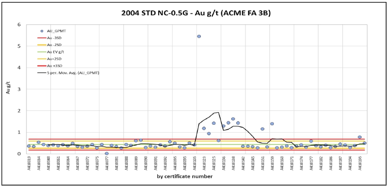
Source: MMTS,
2023
| Figure 11-2: | 2004
Standard Performance NC-2G (ACME) |
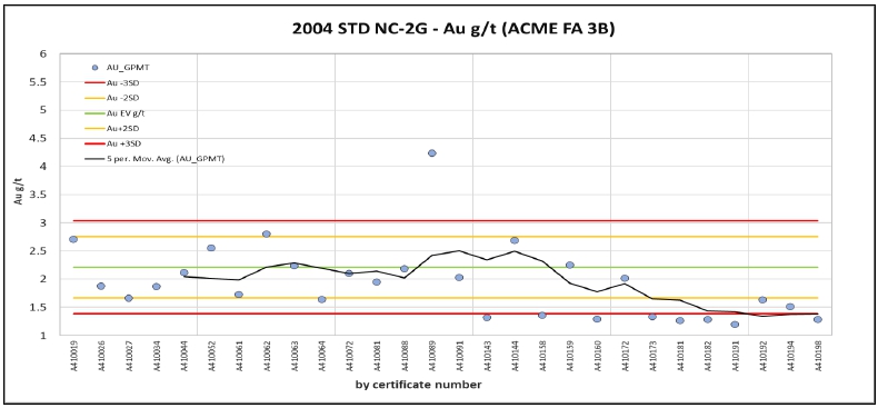
Source: MMTS,
2023
| Courageous Lake Project | Page 85 |
| Pre-feasibility Study and Preliminary Economic Assessment NI 43-101 Technical Report | January 5, 2024 |
Starting
in 2005, Seabridge started inserting blind, fully Au-certified reference materials that reflect the expected range of Au grades of the
mineralized system at Courageous Lake. Table 11-2 details all Standards used for accuracy control from 2005-2012.
| Table 11-2: | Standards
Certification details for Courageous Lake |
Standard
Reference Name |
Certification |
Material
Description |
Expected
Value
(g/t) |
SD |
2
SD |
3
SD |
Number
Submitted |
| CL |
Smee
& Associates |
2006
Courageous Lake core |
2.090 |
±0.065 |
±0.130 |
±0.195 |
407 |
| CL2 |
Smee
& Associates |
2010
Courageous Lake core |
2.073 |
±0.094 |
±0.188 |
±0.282 |
125 |
| KSM |
Smee
& Associates |
2009
KSM core (BC) |
0.774 |
±0.031 |
±0.062 |
±0.093 |
420 |
| CDN-GS-1A |
CDN |
n/a |
0.78 |
±0.04 |
±0.08 |
±0.12 |
128 |
| CDN-GS-1C |
CDN |
Ore
from Specogna deposit |
0.99 |
±0.04 |
±0.08 |
±0.12 |
263 |
| CDN-GS-1P5F |
CDN |
n/a |
1.4 |
±0.12 |
±0.24 |
±0.36 |
17 |
| CDN-GS-2A |
CDN |
Ore
from Specogna deposit |
2.04 |
±0.095 |
±0.19 |
±0.285 |
369 |
| CDN-GS-3K |
CDN |
n/a |
3.19 |
±0.26 |
±0.52 |
±0.78 |
23 |
| CDN-GS-4B |
CDN |
Gold
“ore” from Clone project (BC) |
3.77 |
±0.175 |
±0.350 |
±0.525 |
387 |
| CDN-GS-5A |
CDN |
n/a |
5.1 |
±0.135 |
±0.27 |
±0.405 |
50 |
| CDN-GS-5B |
CDN |
Ore
from Specogna deposit |
4.83 |
±0.19 |
±0.38 |
±0.57 |
123 |
For
2005, Seabridge inserted CDN-GS-1A, CDN-GS-2A, and CDN-GS-5A, while for 2006 the selection was expanded to also include CDN-GS-1C and
CDN-GS-5B. Figure 11-3 illustrates the results for all 934 insertions in a simple normalized plot, using the ‘between-labs’
SDs.
| Courageous Lake Project | Page 86 |
| Pre-feasibility Study and Preliminary Economic Assessment NI 43-101 Technical Report | January 5, 2024 |
| Figure 11-3: | 2005-2006
Standard performance (ACME) – Standard Data Normalized |
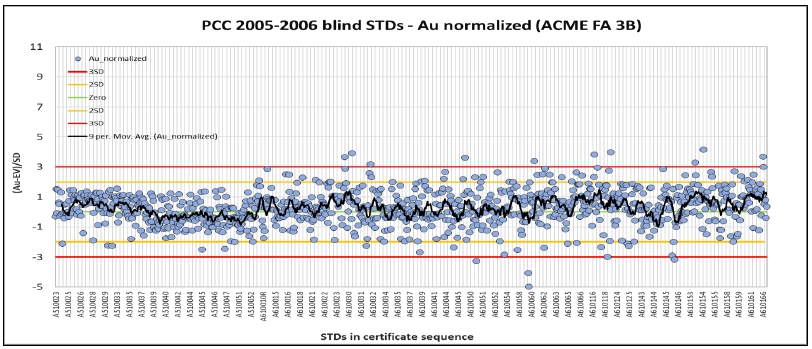
Source: MMTS,
2023
Two tendencies
were noted:
| 1. | The 2005 standards performed more accurately
than the 2006 standards group overall, rarely exceeding the +/-2SD warning thresholds, while the 2006
data displays significantly more scatter and several exceedances of the +/-3SD failure line, both on
the high and the low side. The 9-sample moving average in Figure 11-3 reflects that variability, but
also demonstrates proximity of the assay results to the expected value and only a weak high bias. |
| 2. | 2005 data shows a noticeable shift starting
at certificate A510039, from moderately biased high before to weakly biased low afterwards, possibly
the effect of recalibration procedures at ACME. |
Lab-internal Standard
data was not reviewed for this report. MMTS finds the 2005-2006 accuracy control acceptable.
For
2010-2012, the total count of blind certified reference materials inserted into the sample stream exceeds 1,000. The following plots
represent the individual performances of standards CL, CL2, CDN-GS-4B, and KSM which were the preferred material to insert at the time.
CDN-GS-1P5F
and CDN-GS-3K standards were also inserted in 2012 in very small numbers with acceptable results (not shown in report).
Standard
CL represents a Au standard created from 2006 Courageous Lake drill core, certified by B. Smee and Associates in Vancouver, BC. It was
inserted a total of 407 times between 2010 and 2011 and the results of its assaying generally are without significant bias or trend until
mid-2011 when the grade starts to trend high. CL was not utilized after drill holes CL-178 to the end of the campaign with CL-190.
| Courageous Lake Project | Page 87 |
| Pre-feasibility Study and Preliminary Economic Assessment NI 43-101 Technical Report | January 5, 2024 |
| Figure 11-4: | 2010-2011
Standard Performance (ACME) - CL |
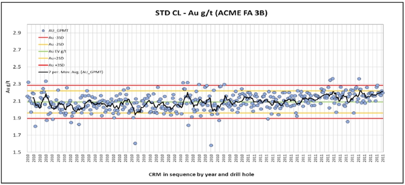
Source:
MMTS, 2023
The
mean of the dataset meets the expected value of 2.09 g/t Au. Scatter, however, is quite significant, with more than 20 results exceeding
the +/-3SD failure threshold which should have triggered batch re-assaying at the time.
CL2
is equally a standard made from Courageous Lake drill core and started getting utilized towards the end of the 2011 campaign (drill hole
CL-162) and into 2012, likely as a replacement of the CL standard discussed above. It was analyzed 125 times in total, though some of
that data refers to duplicates and check-assaying (excluded from plotting).
| Courageous Lake Project | Page 88 |
| Pre-feasibility Study and Preliminary Economic Assessment NI 43-101 Technical Report | January 5, 2024 |
| Figure 11-5: | 2011-2012
Standard Performance (ACME) – CL2 |
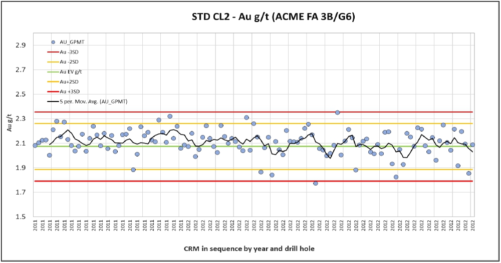
Source:
MMTS, 2023
The
performance of CL2 with only one failure and one near failure is reasonable and the average grade of this population approaches the expected
value of the certificate (2.1 g/t to 2.07 g/t, respectively). The lack of significant trend or bias demonstrates that ACME analyzed this
material accurately.
Standard
CDN-GS-4B was inserted 300 times between 2010 and 2012 for Courageous Lake drilling, with a total of 14 initial failures which were all
on the high side, and several more that exceeded the +/-2SD warning threshold. In response, Seabridge requested 63 refires of said Standards,
demonstrating a functioning quality control protocol. The refire data generally improved accuracy and reduced the failure count to five.
| Courageous Lake Project | Page 89 |
| Pre-feasibility Study and Preliminary Economic Assessment NI 43-101 Technical Report | January 5, 2024 |
| Figure 11-6: | 2010-2012
Standard Performance (ACME) – CDN-GS-4B |
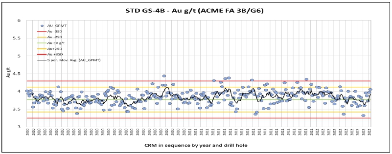
Source:
MMTS, 2023
The
CDN-GS-4B population averages 3.83 g/t Au after the refire procedure which is slightly higher than the expected value of 3.77 g/t. An
additional 24 available assays represent duplicate samples and have been excluded from the plot in Figure 11-6. MMTS finds the performance
of CDN-GS-4B acceptable.
374
‘KSM’ standards were inserted over the course of the three drilling campaigns, excluding duplicates, with 20 total failures
and two very strong low outliers at 0.527 g/t and 0.278 g/t in 2010 (the latter not captured in Figure 11-7).
| Figure 11-7: | 2010-2012
Standard Performance (ACME) - KSM |
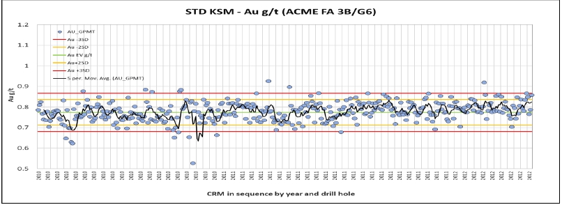
Source:
MMTS, 2023
| Courageous Lake Project | Page 90 |
| Pre-feasibility Study and Preliminary Economic Assessment NI 43-101 Technical Report | January 5, 2024 |
Several
additional results exceed the +/-2SD warning line on either side of the expected value. MMTS is not aware of data from refires Seabridge
may have requested in response to the analytical failures at ACME. The 5-sample moving average line visually confirms the overall proximity
to the expected value of 0.774 g/t, yet also highlights the variability of Au grades in the dataset.
In
summary, the results compare to the other 3 standards in this section of the report and MMTS considers them as acceptable.
A
significant amount of duplicate data was reviewed for this report, concentrating on the regularly produced and industry-standardized
series of field, coarse reject, and pulp duplicates, the latter two of which representing lab-internal duplicates at regular intervals
without client input.
Percentages
in Table 11-3 refer to total samples analyzed, excluding QA/QC. 2010 ACME-internal lab QA/QC was not available at time of report.
| Table 11-3: | Duplicates
Count and Insertion Rates for 2006-2013 |
| |
2004 |
2005 |
2006 |
2010 |
2011 |
2012 |
Total |
| |
count |
% |
count |
% |
count |
% |
count |
% |
count |
% |
count |
% |
count |
% |
| Field
duplicates |
184 |
2.0 |
86 |
2.6 |
223 |
2.8 |
317 |
2.2 |
272 |
2.2 |
148 |
2.1 |
1,230 |
2.2 |
| Reject
duplicates |
279 |
3.0 |
94 |
2.8 |
234 |
2.9 |
n/a |
0.0 |
371 |
3.0 |
228 |
3.2 |
1,206 |
3.0 |
| Pulp
duplicates |
281 |
3.0 |
120 |
3. |
244 |
3.0 |
n/a |
0.0 |
634 |
5.2 |
423 |
5.9 |
1,702 |
4.2 |
| Duplicates
of Standard |
0 |
0.0 |
0 |
0.0 |
0 |
0.0 |
0 |
0.0 |
65 |
0.5 |
13 |
0.2 |
77 |
0.1 |
| Duplicates
of BLK |
0 |
0.0 |
0 |
0.0 |
0 |
0.0 |
0 |
0.0 |
69 |
0.5 |
23 |
0.3 |
89 |
0.2 |
| Total |
744 |
8.0 |
300 |
9.0 |
701 |
8.7 |
317 |
2.2 |
1,411 |
11.5 |
835 |
11.7 |
4,304 |
9.8 |
| 11.11.1.1 | Field
Duplicates |
For
field duplicates, as per sampling procedures described in previous sections, quarter-core sample pairs were taken from 2004-2006 and
2010-2012 and analyzed for Au to assess reproducibility of results. Field duplicate data contains the potential error related to preparation
and size reduction as well as analytical error (see the following rejects and pulp duplicate plots) but its correlation between original
and duplicate sample can also be an indicator for local gold distribution and grain size in the mineralized system tested. In addition,
sample bias detection can be supported by reviewing variability of reported sample weights.
Figure
11-8 demonstrates good correlation of the field duplicate data to the original data across the sampled range of Au grades which includes
the cut-off grade.
| Courageous Lake Project | Page 91 |
| Pre-feasibility Study and Preliminary Economic Assessment NI 43-101 Technical Report | January 5, 2024 |
A
total of 334 pairs were plotted after samples less than detection limit (DL) were removed. In addition, one very strong outlier (drill
hole CL-035, samples SG56730 at 21.9 g/t and SG56731 at 0.12 g/t Au) was removed. Moderate scatter in the 0.1-1.0 g/t Au grade range
does not indicate significant bias.
| Figure 11-8: | 2004-2006
Field Duplicate Performance |
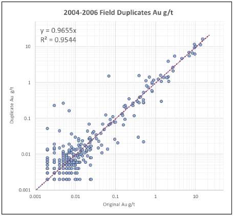
Source:
MMTS, 2023
MMTS
used sample weight data as reported by ACME to calculate a theoretical specific gravity (SG) for each available sample in the Courageous
Lake database and found several pairs within the field duplicate sub-data for which the SG was inconsistent, representing almost 15%
of the 2004-2006 field duplicate dataset:
| ● | A
total of 15 duplicates had no recorded weight, potentially indicating that these are not
field duplicates. |
| ● | For
30 samples (original, duplicate, or both) the reported sample weight was too high relative
to the sample interval to be representative of accurately sampled quarter core. This could
indicate erroneous sampling, occasional half core duplicate sampling, or even a data shift
within Seabridge’s assay database. The inconsistent samples include two sample pairs
from drill holes CL-060 and CL-061, respectively that are well mineralized, while most are
not. In both cases, the actual Au grades between original and duplicate do agree very well. |
All
others weight-inconsistent samples are very low-grade or unmineralized samples which do not contribute to the scatter in the log XY plot
of Figure 11-8. MMTS is not concerned that these finding would significantly influence the confidence or classification of assay data
used in resource estimations.
| Courageous Lake Project | Page 92 |
| Pre-feasibility Study and Preliminary Economic Assessment NI 43-101 Technical Report | January 5, 2024 |
From
2010-2012, a total of 288 field duplicate pairs have been plotted in Figure 11-9, after removing all data points <0.005 g/t (the detection
limit of ACME’s G6 fire assay method) and one high outlier pair (samples 513565 and 513566 of drill hole CL-112).
As
was the case for the 2004-2006 field duplicates, the sample weight of at least one partner of several duplicate pairs was inconsistent
with quarter core sampling (generally too high, pointing towards either half-core samples or classification errors in the Courageous
Lake database) or missing from the records. This affected 10% of duplicate pairs.
Weight
reporting from 2010 onwards included two decimals for much better resolution and accuracy, likely an indication of improved automatization
at the prep facility in Yellowknife.
| Figure 11-9: | 2010-2012
Field Duplicate Performance |
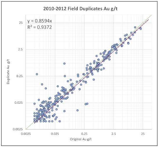
Source:
MMTS, 2023
The
field duplicates demonstrate very good precision despite the occasional sample weight discrepancies. There were fewer than 10 outliers
at low grades which are equally distributed and do not indicate sample bias. The linear regression is overall slightly original-positive,
influenced by the two highest-grade pairs both being +30% original-positive. The QP finds the results acceptable.
| Courageous Lake Project | Page 93 |
| Pre-feasibility Study and Preliminary Economic Assessment NI 43-101 Technical Report | January 5, 2024 |
| 11.11.1.2 | ACME
Reject Duplicates |
ACME
reported a total of 607 lab-internal reject reruns from 2004-2006, 1 for every 30 samples provided by Seabridge. The data correlates
very well as shown by the R2 of 0.99, with negligible scatter >0.25 g/t Au, demonstrating very good precision, as illustrated in Figure
11-10.
| Figure 11-10: | 2004-2006
Coarse Reject Duplicate Performance (ACME) |
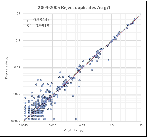
Source:
MMTS, 2023
The
following plot in Figure 11-11 below contains assay data of 221 coarse reject duplicate pairs as produced by ACME’s lab-internal
QA/QC protocol of 2011 and 2012 (2010 coarse reject duplicate and pulp duplicate data were not available at the time of report). All
data below 0.005 g/t Au was removed.
The
correlation is very good, data scatter is low, and a significant trend or bias is not discernible which confirms acceptable size reduction
procedures at ACME’s preparation facilities in Yellowknife, NWT.
| Courageous Lake Project | Page 94 |
| Pre-feasibility Study and Preliminary Economic Assessment NI 43-101 Technical Report | January 5, 2024 |
| Figure 11-11: | 2011-2012
Coarse Reject Duplicate Performance (ACME) |
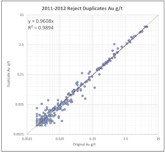
Source:
MMTS, 2023
| 11.11.1.3 | ACME
Pulp Duplicates |
As
with the lab reject rerun performance, the ACME-internal 2004-2006 pulp rerun data showed near-perfect reproducibility for samples >0.2
g/t Au. All data <0.005 g/t was removed before plotting ACME-internal pulp duplicate assay results as illustrated in Figure 11-12
and Figure 11-13.
Both
R2 and slope of the linear trendline are near perfect, demonstrating good analytical precision at ACME Labs in Vancouver, BC.
In
summary, MMTS views the multi-stage duplicate data produced by Seabridge and ACME as acceptable in quantity, drill hole and grade distribution,
and results.
| Courageous Lake Project | Page 95 |
| Pre-feasibility Study and Preliminary Economic Assessment NI 43-101 Technical Report | January 5, 2024 |
| Figure 11-12: | 2004-2006
Pulp Duplicate Performance (ACME) |
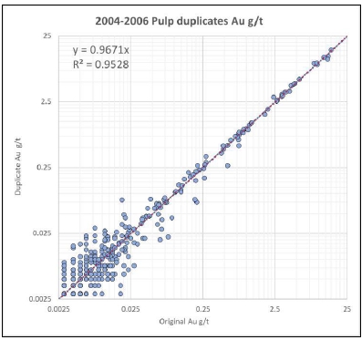
Source: MMTS,
2023
| Figure 11-13: | 2011-2012
Pulp Duplicate Performance (ACME) |
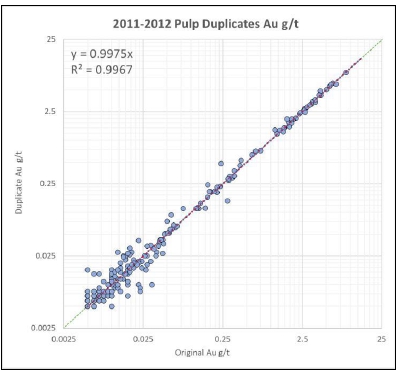
Source: MMTS,
2023
| Courageous Lake Project | Page 96 |
| Pre-feasibility Study and Preliminary Economic Assessment NI 43-101 Technical Report | January 5, 2024 |
To
control potential inter-sample contamination during preparation at ACME, Seabridge utilized two different materials for blanks: in 2004
a blend of project-related very low-grade samples collected in 2003 (CL_BLANK) and in 2005-2006, a certified barren material was purchased
from WCM in Burnaby, BC (BL-3/BL103).
The
data is presented against a warning threshold of 5*DL and a failure threshold of 10*DL as shown in Figure 11-14.
Given
the naturally elevated Au background in the sample material used in 2004, the very consistent exceedance of the warning line and frequent
exceedance of the failure threshold during the first 30% of the program is not interpreted as a contamination issue at ACME. For the
remainder of the 2004 program, a less mineralized but not barren blend was used. Six failures were noted for that period but again, with
the apparent heterogeneity of the material and the overall concept of contamination (and accuracy) control at Seabridge at the time in
mind, MMTS does not see clear evidence for systematic contamination at ACME.
| Figure 11-14: | 2004
Blank Performance (ACME) |
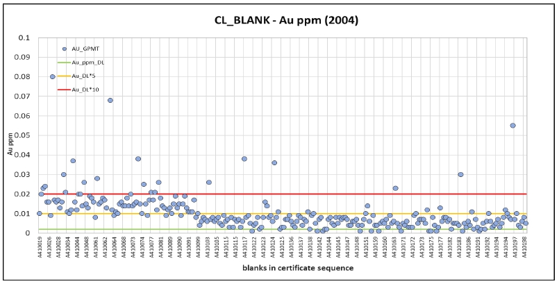
Source:
MMTS, 2023
The
2005-2006 blind blank BL103 appeared suitable to monitor contamination control performance at ACME as illustrated in Figure 11-15. The
10*DL failure line was met once only, which is a very good result considering a total of 902 blanks were inserted during those campaigns.
| Courageous Lake Project | Page 97 |
| Pre-feasibility Study and Preliminary Economic Assessment NI 43-101 Technical Report | January 5, 2024 |
| Figure 11-15: | 2005-2006
Blank Performance (ACME) |
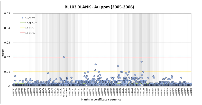
Source:
MMTS, 2023
The
warning threshold was exceeded several times, specifically between late March and mid-April 2006, which could indicate that during that
time, preparation and cleaning procedures at ACME may not have been followed properly.
MMTS
reviewed the Au assay results of the samples preceding the blanks with elevated Au during that time and could not identify a definite
connection between higher grade samples and contaminated blanks. Pulverization capacities at ACME in 2006 are not known to MMTS and it
could be possible that the sample preceding the blank in the Seabridge sample series is not the same sample preceding the blank in the
ACME prep series.
MMTS
finds the 2004-2006 data acceptable and is not concerned about a possible weak contamination at very low grades influencing the modelling
results.
For
the 2010-2012 drilling campaigns, Seabridge inserted 1,344 blind blanks into the sample streams. Starting in 2012, Seabridge adjusted
the fire assay method it requested ACME to perform from the previous 30-g fire assay ICP-ES procedure (ACME 3B01) to exclusively 30g
fire assay method with AAS finish (ACME G6).
The
G6 detection limit is slightly higher at 0.005 g/t compared to 3B (0.002 g/t), resulting in a shift in warning and failure threshold
as shown in Figure 11-16.
| Courageous Lake Project | Page 98 |
| Pre-feasibility Study and Preliminary Economic Assessment NI 43-101 Technical Report | January 5, 2024 |
| Figure 11-16: | 2010-2012
Blank Performance (ACME) |
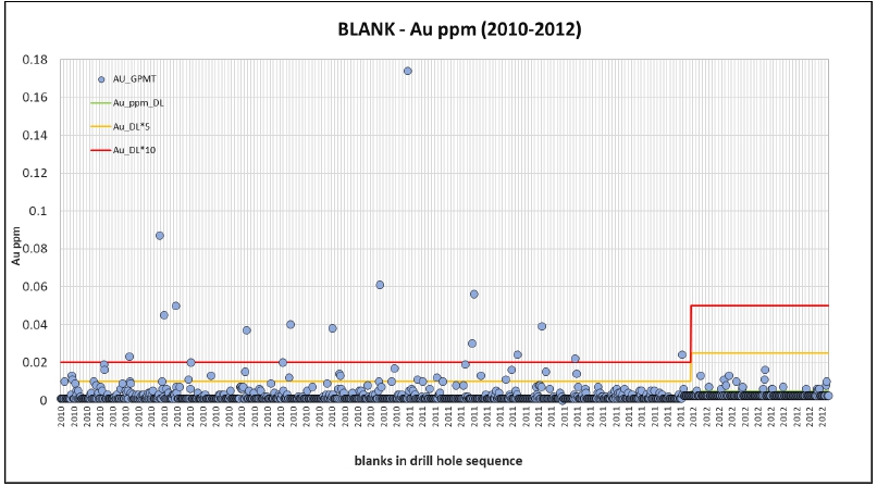
Source:
MMTS, 2023
Fifteen
blanks (1.6%) failed by exceeding the 10*DL threshold between 2010 and 2011, with a high of 0.174 g/t Au in a blank in early 2011. The
samples preceding this outlier were reviewed but none were sufficiently mineralized to explain the poor result as a potential inter-sample
contamination. Similarly, the sample preceding the second highest outlier at 0.087 g/t in 2010 only runs 0.24 g/t Au which seems insufficient
to cause meaningful contamination.
Twenty-seven
or <3% of blanks exceed the warning line at 0.01 ppm for the 2010-2011 period.
MMTS
accepts the results because of the overall very low Au content in blanks, the apparent lack of evidence that preceding high-grade samples
systematically caused the elevation of Au grade in blanks, and the rather sporadic and even distribution of failures over time. However,
unexplained contamination indicators are a concern, and a batch rerun would have been appropriate. MMTS did not review the ACME-internal
blank performance.
In
2004, Seabridge had check-assaying performed by sending select and frequently mineralized rejects to SGS Lakefield. Of the initial 236
available assay pairs, four strong outliers were removed from the scatter plot. These are consecutive samples in drill hole CL-005 (30.99-36.99
m) that are strongly mineralized in the ACME data set (0.5-7.9 g/t Au) yet approach detection limit in the SGS Lakefield data (0.01-0.03
g/t Au), likely indicating a sample mix-up, not actual analytical variability that the plot aims to show. When these outliers are removed
the 2004 SGS Lakefield check-assay results demonstrate very good correlation to the original ACME Au data as illustrated in Figure 11-17.
The slightly SGS-positive tendency in the data as indicated by y=1.1373x is caused by the high-grade pair at 48.5 g/t (ACME) to 66.6
g/t (SGS), respectively. Removing this sample as well results in a y of 0.983x and an R2 of 0.973.
| Courageous Lake Project | Page 99 |
| Pre-feasibility Study and Preliminary Economic Assessment NI 43-101 Technical Report | January 5, 2024 |
| Figure 11-17: | 2004
Check-Assay Performance (SGS Lakefield) |
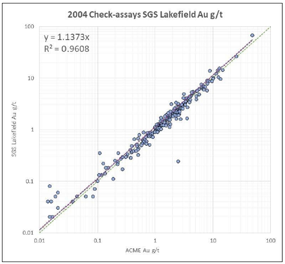
Source:
MMTS, 2023
For
2005 and 2006, Seabridge chose to work with ALS Chemex in Vancouver, BC for check-assay purposes and requested the 30-g fire assay Au-AA23
method with AA finish for a total of 1,382 samples, including the occasional field duplicate pulp. Overall, a much larger number of unmineralized
material was selected compared to the 2004 exercise with SGS Lakefield, leading to a drop in mean Au grade to 0.27 g/t, while the 2004
data averaged 2.68 g/t Au.
For
the scatter plot in Figure 11-18, all data at or below the detection limit of 0.002 g/t for ACME and all data below the 0.005 g/t ALS
detection limit were removed which resulted in a remaining population of 1,313 pairs. The correlation is acceptable despite substantial
scatter across the data range since no relevant bias was observed. Removing the highest-grade ALS-positive outlier (7.1 g/t vs. 16.05
g/t) improves the R2 to 0.973 while y stays very close to 1x.
| Courageous Lake Project | Page 100 |
| Pre-feasibility Study and Preliminary Economic Assessment NI 43-101 Technical Report | January 5, 2024 |
| Figure 11-18: | 2005-2006
Check-Assay Performance (ALS) |
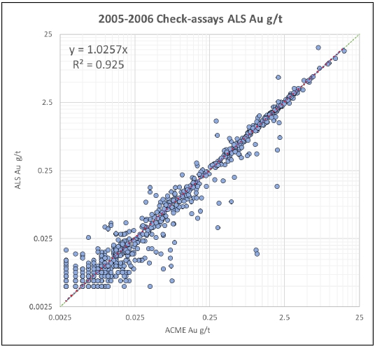
Source:
MMTS, 2023
A
total of 1,920 check-assays of primary and original sample material from 2011-2012 drilling was made available to MMTS for review. An
additional 213 check-assays representing Standards, blanks, or a second analysis of the check-assay pulp were not considered for plotting.
For the log scatterplot in Figure 11-19, all assay results below the respective DL have been removed with 918 pairs covering the range
from DL to 10 g/t remained.
The
two data sets correlate well as indicated by a R2 of 0.976. Most of the population plots at or in proximity to the 1-to-1 line and is
very slightly ALS-positive despite the overall y of 0.945x. 475 samples returned a higher ALS result, while 405 have a higher ACME result
(38 sample pairs have matching Au grade). The noticeable scatter in the plot is caused by 40 samples of reasonably random and unbiased
distribution (<5%) predominantly in the 0.05-1 g/t Au grade range.
The
results are acceptable and indicate that the ACME data used in resource estimation could be conservative.
| Courageous Lake Project | Page 101 |
| Pre-feasibility Study and Preliminary Economic Assessment NI 43-101 Technical Report | January 5, 2024 |
| Figure 11-19: | 2011-2012
Check-Assay Performance (ALS) |
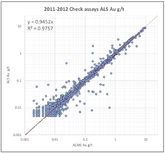
Source:
MMTS, 2023
| 11.12 | Quality
Assurance and Quality Control - Walsh Lake |
The
review of the Walsh Lake QA/QC confirms in large parts what has been compiled and interpreted for Courageous Lake in previous sections
of this report. Pre-2010 drilling was limited, and except for field duplicates and a small number of check-assays from 2006, no QA/QC
data was provided to MMTS (Table 11-4). No historic data (pre-Seabridge) was used for the Walsh lake Resource Estimate.
| Table 11-4: | QA/QC Insertion Counts and
% of Total by Year - Walsh Lake |
| |
2006 |
2010 |
2012 |
2013 |
Total |
| |
count |
% |
count |
% |
count |
% |
count |
% |
count |
% |
| Total
intervals sampled |
189 |
77.5 |
352 |
91.7 |
5,464 |
75.7 |
5,527 |
73.6 |
11,532 |
75.1 |
| Total
blanks |
n/a |
0.0 |
12 |
3.1 |
190 |
2.6 |
219 |
2.9 |
421 |
2.7 |
| Total
STDs |
n/a |
0.0 |
13 |
3.4 |
180 |
2.5 |
218 |
2.9 |
411 |
2.7 |
| Courageous Lake Project | Page 102 |
| Pre-feasibility Study and Preliminary Economic Assessment NI 43-101 Technical Report | January 5, 2024 |
| |
2006 |
2010 |
2012 |
2013 |
Total |
| |
count |
% |
count |
% |
count |
% |
count |
% |
count |
% |
| Total
Duplicates |
7 |
11.9 |
7 |
1.8 |
647 |
9.0 |
670 |
8.9 |
1,353 |
8.8 |
| Total
check-assays |
26 |
10.7 |
0 |
0.0 |
576 |
8.0 |
677 |
9.0 |
1,279 |
8.3 |
| Total
rerun+refire |
0 |
0.0 |
0 |
0.0 |
161 |
2.2 |
200 |
2.7 |
627 |
2.4 |
| Total |
244 |
100.0 |
384 |
100.0 |
7,218 |
100.0 |
7,511 |
100.0 |
15,357 |
100.0 |
| 11.12.1 | 2010
QA/QC Procedures |
To
ensure that the 2010 and later Seabridge drill hole assays were suitable for resource estimation, several systems were put into place
to measure the accuracy and reproducibility of the assays. Seabridge geologists and/or technicians inserted barren “blank”
material and various certified standards into the sample stream at a frequency of one blank per 30 regular samples. The blank material
consisted of decorative marble aggregate that was purchased in Yellowknife. Multiple different certified standards were randomly inserted
into the sample stream at a frequency target of one standard per 30 regular samples.
Field
duplicate samples were collected at a frequency of about one duplicate per 50 regular samples. These duplicates were generated by sawing
the initial half-split of core into two equal pieces so that the “original” and the “duplicate” each represented
one quarter of the original core.
After
assay results were reported by ACME, Seabridge geologists selected 11% of the ACME pulps and had them shipped to the ALS in Vancouver,
BC, where they were assayed for gold. This data was not available to MMTS at the time of this report and has therefore not been included
in the check-assay discussion below.
| 11.12.2 | 2012-2013
Core Sampling and QA/QC Procedures |
To
ensure that drill hole assays are suitable for resource estimation, several systems were put into place to the measure the accuracy and
reproducibility of the assays. Reject material is stored at the Yellowknife facility until all analyses and checks are completed and
then sent to Matrix Logistics’ for holding until they are shipped back to site.
| ● | A
duplicate sample of a primary was made from ¼ split of a core sample at the rate of
1 duplicate in every 40 samples. |
| ● | Blank
samples were inserted in the sample stream at a rate of 1 in 35 samples or 2.8% of the total. |
| ● | Standards
were inserted in the sample stream at a rate of 1 in 35 samples or 2.8% of the total samples. |
| ● | ACME
completes random re-assays of individual samples on 8% of each batch of samples submitted
to the lab as part of their protocols. |
| ● | ACME
also inserts their own certified standards and blanks at the rate of >5% each as part
of their internal QA/QC protocols. |
| Courageous Lake Project | Page 103 |
| Pre-feasibility Study and Preliminary Economic Assessment NI 43-101 Technical Report | January 5, 2024 |
| ● | All
Seabridge samples containing 4.0 g/t Au or greater were requested to be re-fired from the
original pulp. MMTS could not confirm this from the data provided. |
| ● | All
Seabridge samples containing 10.0 g/t Au or greater were reprocessed from the coarse reject
material and analyzed using screen fire assay methods. |
Sample
collection included the insertion of six different standards (see Table 11-5 below for details). Four of the six standards are certified
and were purchased from CDN Labs of Langley British Columbia, Canada. The remaining two standards were composed of crushed drill core
from Seabridge Golds’ KSM property in British Columbia as well as from crushed drill core from previous Courageous Lake drill campaigns.
These standards were subject to industry standard round-robin analyses at several assay labs.
Several
different blind standards (CRM or certified reference material) were inserted by Seabridge geologists to monitor assay result
accuracy (Table 11-5). The standards cover a comparatively high-grade range of 0.77 g/t Au to 3.77 g/t Au and 2 of them were
custom-made from selected drill core samples of Courageous Lake adjacent to Walsh Lake.
Figure
11-20 to Figure 11-23 demonstrate the Standards respective performances, using the inter-laboratory two and three SD of the certification
process as generic warning and failure thresholds. CL and CDN-GS-4B are not graphically presented because of their low count but MMTS
has reviewed the respective data and attests to acceptable results.
| Table 11-5: | Standards certification details
for Walsh Lake |
Standard
Reference
Name |
Certification |
Material
Description |
Expected
Value
(g/t) |
SD |
2 SD |
3 SD |
Number
Submitted |
| CL |
Smee & Associates |
2006 Courageous Lake core |
2.090 |
±0.065 |
±0.130 |
±0.195 |
10 |
| CL2 |
Smee & Associates |
2010 Courageous Lake core |
2.073 |
±0.094 |
±0.188 |
±0.282 |
121 |
| KSM |
Smee & Associates |
2009 KSM core (BC) |
0.774 |
±0.031 |
±0.062 |
±0.093 |
116 |
| CDN-GS-1P5F |
CDN |
n/a |
1.4 |
±0.12 |
±0.24 |
±0.36 |
72 |
| CDN-GS-3K |
CDN |
n/a |
3.19 |
±0.26 |
±0.52 |
±0.78 |
86 |
| CDN-GS-4B |
CDN |
Gold “ore” from Clone project (BC) |
3.770 |
±0.175 |
±0.350 |
±0.525 |
6 |
| Courageous Lake Project | Page 104 |
| Pre-feasibility Study and Preliminary Economic Assessment NI 43-101 Technical Report | January 5, 2024 |
| Figure 11-20: | Walsh Lake 2012-2013 Standard
Performance CL2 (ACME) |
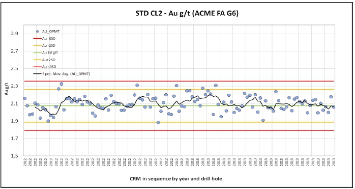
Source: MMTS,
2023
| Figure 11-21: | Walsh Lake 2010-2013 Standard
Performance KSM (ACME) |
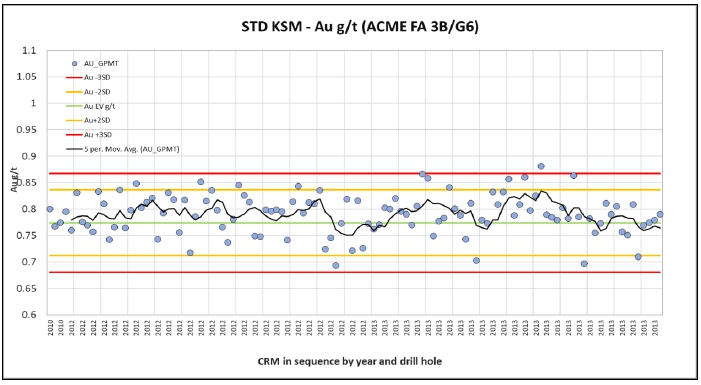
Source: MMTS,
2023
| Courageous Lake Project | Page 105 |
| Pre-feasibility Study and Preliminary Economic Assessment NI 43-101 Technical Report | January 5, 2024 |
| Figure 11-22: | Walsh Lake 2012-2013 Standard
Performance CDN-GS-1P5F (ACME) |
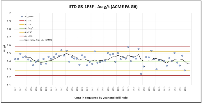
Source: MMTS,
2023
| Figure 11-23: | Walsh Lake 2012-2013 Standard
Performance CDN-GS-3K (ACME) |
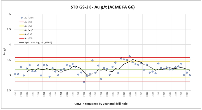
Source: MMTS,
2023
| Courageous Lake Project | Page 106 |
| Pre-feasibility Study and Preliminary Economic Assessment NI 43-101 Technical Report | January 5, 2024 |
The
results of the four standards presented here demonstrate moderate variability centered around the certified Au values (Au EV g/t) and
within the +/-2SD window, with a total of three exceedances of the +/-3SD failure threshold and a weak high bias in KSM and GS-1P5F.
The three failures should have triggered batch reruns at ACME at the time but are overall not a concern because of their unrelated occurrence
and proximity to the failure line. No significant trends across multiple standards were identified. MMTS finds the performance acceptable.
Seabridge
defined field duplicate samples (¼ core samples) at consistent intervals across all drilling campaigns, resulting in a total of
250 pairs to control the Walsh Lake Resource Estimate dataset (equaling 2.2% relative to sampled intervals).
In
addition, both reject duplicate and pulp duplicate data as produced by ACME is being presented in this report in the form of simple linear
regressions to assess potential reproducibility issues at various stages of sample size reduction. MMTS did not review the lab-internal
duplicates data for 2006 and 2010.
Total
duplicate data in this report sums to 1,353 analyses, including duplicates of blanks and standards, as shown in Table 11-6. Focusing
on Au and actual rock samples alone, the total is 961 as a substantial number of pulp duplicates was not analyzed for Au. Percentages
in Table 11-6 refer to total samples analyzed, excluding QA/QC.
Figure
11-24 demonstrates good correlation between the original ¼ core sample and its duplicate partner. Significant scatter as shown
is to be expected in a structurally controlled and comparatively high-grade epithermal deposit.
| Table 11-6: | Duplicates Count and Insertion
Rates for 2006-2013 |
| |
2006 |
2010 |
2012 |
2013 |
Total |
| |
count |
% |
count |
% |
count |
% |
count |
% |
count |
% |
| Field
duplicates |
7 |
4.4 |
7 |
2.0 |
117 |
2.1 |
119 |
2.2 |
250 |
2.2 |
| Reject
duplicates |
n/a |
0.0 |
0 |
0.0 |
173 |
3.2 |
183 |
3.3 |
356 |
3.1 |
| Pulp
duplicates |
n/a |
0.0 |
0 |
0.0 |
337 |
6.2 |
335 |
6.1 |
672 |
5.8 |
| Duplicates
of Standard |
0 |
0.0 |
0 |
0.0 |
9 |
0.2 |
15 |
0.3 |
24 |
0.2 |
| Duplicates
of BLK |
0 |
0.0 |
0 |
0.0 |
11 |
0.2 |
18 |
0.3 |
29 |
0.3 |
| Total |
7 |
4.4% |
7 |
2.0 |
647 |
11.8 |
670 |
12.1 |
1,331 |
11.5 |
| Courageous Lake Project | Page 107 |
| Pre-feasibility Study and Preliminary Economic Assessment NI 43-101 Technical Report | January 5, 2024 |
| Figure 11-24: | Walsh Lake Field Duplicate
Performance |
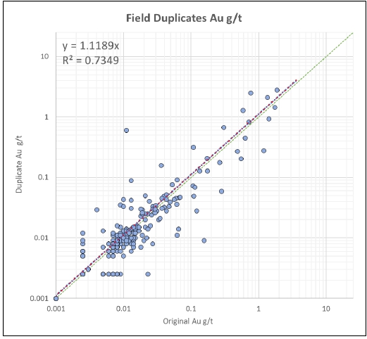
Source:
MMTS, 2023
During
the review process, MMTS utilized the respective sample weights as reported by ACME and the interval lengths to calculate a simple theoretical
specific gravity for each sample, duplicate or not, to highlight areas of poor sampling and potential mislabeling. The data of the field
duplicates was found to be overall consistent with unbiased quarter core sampling as the pairs weight data ARD rarely exceeded 15%, though
one single duplicate was removed from the plot because of a significant variance in sample weight to the original (likely a sampling
error) and another had the duplicate sample weight missing.
MMTS
has therefore no indication that poor sampling has contributed significantly to the scatter in Figure 11-24.
As
should be expected, lab-internal coarse reject duplicates of Walsh Lake samples taken from drill holes used in resource estimation show
very good correlation to the data of the original sample with respect to Au as illustrated in Figure 11-25. One single sample had to
be removed as no over-limit data was available for the duplicate.
Noticeably,
basically all higher-grade >1 g/t pairs plot very close to the center line while the medium-grade population 0.05-1.0 g/t exhibits
substantial scatter, similar to the field duplicate results. This could indicate that Au mineralization at Walsh Lake is relatively fine-grained.
| Courageous Lake Project | Page 108 |
| Pre-feasibility Study and Preliminary Economic Assessment NI 43-101 Technical Report | January 5, 2024 |
| Figure 11-25: | Walsh Lake Coarse Reject Duplicate
Performance (ACME) |
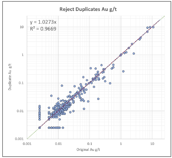
Source:
MMTS, 2023
Figure
11-26 characterizes the performance of 333 pulp duplicates selected by ACME, after removing >300 duplicates that were not analyzed
for Au from the overall available dataset of 672, and one for which the over-limit Au data was not generated or reported.
Two
outliers, both with strong duplicate-positive bias, negatively affect the correlations of the pulp duplicate data, leading to a surprisingly
poor R2 of <0.9. Removing the two outliers results in an R2 of 0.98, as shown on the plot.
| Courageous Lake Project | Page 109 |
| Pre-feasibility Study and Preliminary Economic Assessment NI 43-101 Technical Report | January 5, 2024 |
Figure
11-26: Walsh Lake Pulp Duplicate Performance (ACME)
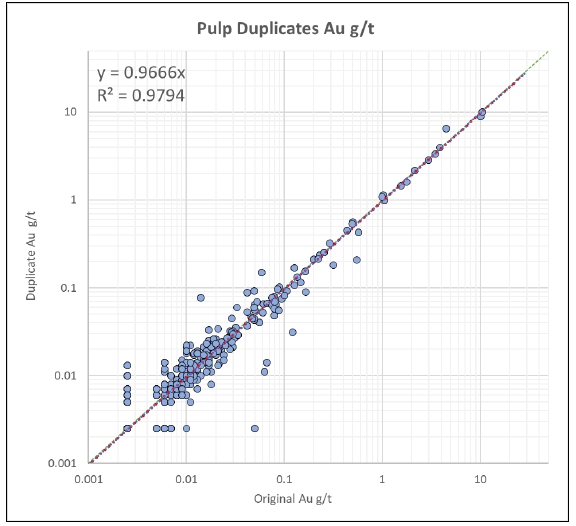
Source:
MMTS, 2023
In
summary, the Walsh Lake duplicate data demonstrates acceptable and increasing reproducibility across the various stages of sample reduction.
One
single blank material was utilized 421 times for contamination control during the three years of drilling at Walsh Lake that is being
considered for resource estimation (2010, 2012-2013). The blanks were inserted blind with a mean sample weight of 0.84 kg. Insertion
rates varies between 2.6% and 3.1% relative to total samples analyzed for an average of 2.7%. Relative to drill core samples only, the
rate is 3.65%.
Figure
11-27 displays its performance across these years, allowing for determination of potential cross-contamination during crushing and pulverizing
at ACMEs preparation facilities. 2010 blanks were analyzed by ACMEs 3B fire assay Au method with a detection limit of 2 ppb while for
2012 and 2013 ACMEs G6 fire assay method was requested by Seabridge (detection limit for the method is 0.005 ppm).
| Courageous Lake Project | Page 110 |
| Pre-feasibility Study and Preliminary Economic Assessment NI 43-101 Technical Report | January 5, 2024 |
| Figure 11-27: | Walsh
Lake 2010-2013 BLANK Performance (ACME) |
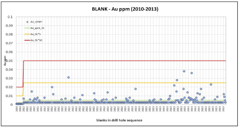
Source:
MMTS, 2023
Four
blanks exceeded the 5*DL warning threshold in 2012 (one blank) and 2013 (three blanks), but the results are overall acceptable. Twentynine
(29) blanks of 2012-2013 were automatically analyzed twice by ACME, with 13 by FA Au, with similarly acceptable results and a high of
0.02 g/t.
For
the years 2012 and 2013, Seabridge selected >10% of previously prepped and analyzed samples (by ACME) and sent the respective pulps
to ALS in Vancouver for check-assay purposes in 2013, requesting both FA Au (Au-AA23, Figure 11-28) and multi-element ICP assays via
aqua regia digestion (ME-ICP41).
Figure
11-28 shows a logarithmic scatter plot with simple linear regression between original ACME data and check-assay ALS data, produced from
1,200 rock samples and their pulp materials. The correlation between the datasets is good but does display a surprisingly strong, but
largely unbiased, scatter between 0.05 and 1 g/t and a bias towards the original ACME assay results at <0.05 g/t Au.
MMTS
considers the ACME -positive bias of unmineralized to weakly mineralized material as inconsequential to the resource estimation results
of this report.
| Courageous Lake Project | Page 111 |
| Pre-feasibility Study and Preliminary Economic Assessment NI 43-101 Technical Report | January 5, 2024 |
| Figure 11-28: | Walsh Lake Check-Assay Performance
(ALS) |
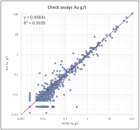
Source:
MMTS, 2023
For
the 2013 sample pulps, Seabridge expanded the check-assay program to include meaningful blank and standard material numbers from the
blind insertion program of the original campaign. The Standard data plot for this data is shown in Figure 11-29.
38
standards were check-assayed by ALS in 2013, representing all standards as shown in Table 11-5 above for Walsh Lake. The data has been
normalized using the certified Au value (expected value or EV) and the intra-lab calculated and certified SD. The data is overall acceptable
but does include four results which approach or exceed the +/-3SD threshold that would qualify as a failure line in the original ACME
dataset and quality control for accuracy and therefore trigger a batch rerun.
In
addition, the results are moderately biased high with an increasing trend towards the end of the program. This indicates that Seabridge’s
Walsh Lake ACME data used for resource estimation could be considered conservative.
| Courageous Lake Project | Page 112 |
| Pre-feasibility Study and Preliminary Economic Assessment NI 43-101 Technical Report | January 5, 2024 |
| Figure 11-29: | Walsh Lake Check-Assay of Standard
(ALS) |
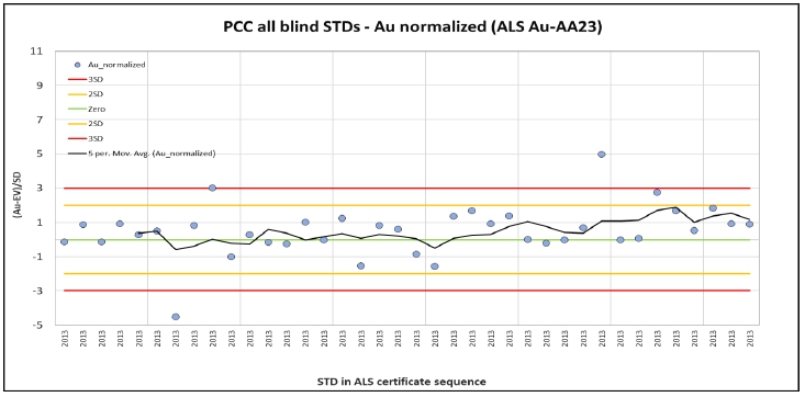
Source: MMTS,
2023
| 11.13 | Comment
on Sample Preparation, Analyses and Security |
With the exception
of the 2004 accuracy control at Courageous Lake, MMTS finds the QA/QC protocols and results at both Courageous Lake and Walsh Lake to
be acceptable.
Despite substantial
variability, partially caused by a lack of data availability, QA/QC insertion rates are overall in line with industry standards. Secondary
lab check-assay efforts from 2005 onwards were commendable.
MMTS recommends
a review of the Courageous Lake database with focus on the following:
| ● | Completeness
of the ICP-assay results in the Courageous Lake database as three certificates from 2010
were identified to be missing from recent data exports. |
| ● | Check-assays
data availability of 2005-2006 (ALS) and 2010 (ALS) and possible certificate misalignments
(ACME vs. ALS). |
| ● | Coding
and classifications, for example Check-Type L (undefined lab duplicates sample B). |
| ● | a
review of sample weight data for field duplicates, in 2004-2006, to confirm classification
and eliminate possible sampling or recording inconsistencies. |
| ● | SGS
Lakefield check-assay data and certificate availability (2004). |
| ● | Refire
data provided in recent exports did not always meet quantity expectations from refire protocols. |
| Courageous Lake Project | Page 113 |
| Pre-feasibility Study and Preliminary Economic Assessment NI 43-101 Technical Report | January 5, 2024 |
The
data verification had been done previously by RMI between 2002 and 2013 (Tetra Tech, 2012). This data verification has been reviewed
and some additional verification work undertaken. The following section follows the Lechner report with additional verification done
by the current QP.
The
QP visited the Courageous Lake and Walsh Lake deposits on June 21, 2023. During the visit the camp was toured, the core storage areas
were examined and the core from both deposits was examined. Several drill holes were checked for the collar locations and the overall
drilling was determined to match the drill hole database. The geologist provided an overview of the geology, the sample preparation and
the core security measures used by Seabridge.
| 12.3 | Seabridge
Database Certificate Checks |
Since
2002, Seabridge has collected all of the data for this project. RMI had verified the data collected by Seabridge by comparing certified
assays against the provided electronic assay database as outlined in reports by RMI in 2002, 2004, 2006 and 2013 (TetraTech, 2012). MMTS
has compared the Seabridge certificates to the data provided by Seabridge. 5,500 assays were checked from 59 certificates from Courageous
Lake and 7 certificates from Walsh Lake. The assays were selected to contain data within the mineralized zones and to be from all years
between 2003 and 2013 of lab data. There were no errors found in the database, indicating that the database has been correctly built
from the Seabridge certificate data.
A
significant portion of the data was collected during the 1980s and 1990s by major mining companies (Noranda and Placer Dome). The assay
and geologic data that were provided to Seabridge by the previous owners of the property were compared against certified assay laboratory
sheets and drill hole logs and found to be accurately entered (Lechner, 2013).
Point
validation has been used to compare the historic drill campaign Au assay values to the more recent Seabridge drilling. Point
Validation interpolates the assays at the historic locations using all data except the historic data, thus, theoretically, removing
any variations in grade due to location alone. Figure 12-1 illustrates a comparison of the Cumulative Probability Plots (CPPs) of
the Placer Dome data with that of all other data at the same composited locations. Interpolations used only data within 7.5 m of the
historic data locations. Figure 12-2 illustrates the same comparison for the Noranda era drilling. Both plots indicate that there is
no significant bias to the historic data, and therefore it has been used for the Resource Estimate.
| Courageous Lake Project | Page 114 |
| Pre-feasibility Study and Preliminary Economic Assessment NI 43-101 Technical Report | January 5, 2024 |
| Figure 12-1: | Point Validation of Placer-Dome
Historic Data |
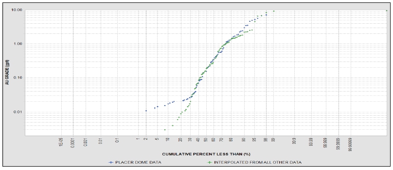
Source: MMTS,
2023
| Figure 12-2: | Point Validation of Noranda
Historic Data |
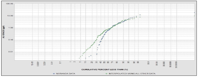
Source: MMTS,
2023
| Courageous Lake Project | Page 115 |
| Pre-feasibility Study and Preliminary Economic Assessment NI 43-101 Technical Report | January 5, 2024 |
Geologic
data used in constraining the estimation of block model gold resources consisted of three-dimensional wire frames that subdivide the
deposit into similar alteration, sulfide mineralogy, and gold grade zones. Seabridge determined through its work that gold distribution
in the FAT deposit can be described by:
| ● | sericite
alteration intensity |
| ● | presence
of acicular arsenopyrite |
| ● | presence
of silicic alteration |
| ● | +/-
intensity of foliation |
| ● | +/-
presence of gray-blue quartz veins |
These
characteristics were prioritized in Seabridge’s drill core logging and summarized, where possible, from drill core that was logged
by Placer Dome and Noranda. The parameters listed above were then plotted on cross sections every 50 m along the strike of the FAT deposit.
Seabridge was able to define 13 mineralized zones using the aforementioned criteria. The sectional interpretations were intersected to
20 m-spaced level plans and reconciled to minimize projection errors. The 5 x 5 x 5 m model blocks were then coded with 13 mineral zone
wireframes. The model blocks were thoroughly checked to make sure that the block model codes accurately depicted the mineral zone wire
frame outlines. The codes within the block model appear to match the solids adequately.
Noranda
and Placer Dome used specific gravity values of 2.70 and 2.75 g/cm3 for their respective non-NI 43-101 compliant Resource
Estimates. According to Seabridge personnel, Placer Dome collected a significant number of density measurements; however, this data is
not available. Seabridge geologists have collected 493 density determinations from their own diamond drill core within the FAT zone.
Specific gravity analyses were obtained by the water displacement method by weighing the air-dried core in air and then in water using
a triple beam balance and fishing line. Determinations were made every 40 or 50 m down-the-hole. The average “wet” density
from these measurements taken from 82 drill holes was 2.72 g/cm3. The average bulk density calculated by RMI for overburden
(2.00 g/cm3), non-diabase rock (2.72 g/cm3), and diabase (2.85 g/cm3) was checked and has been used
for the current Resource Estimate.
Topography
and drill holes had been previously checked by RMI (TetraTech, 2012), with collars adjusted to topography where necessary. No collars
material to the resource had required adjustment. No discrepancies of the topography with the current drill hole collars of the current
modelling were found.
Core
hole recovery data were obtained for most of Placer Dome’s drill holes and for all of Seabridge’s core holes. Because of
the competent nature of the rocks within the CLGB package, core recovery was found to be exceptionally high. Core recoveries averaged
99% for the primary mineral zones (i.e. 3, 4, and 5). Furthermore, during the 2023 site visit, the QP compared the core recovery with
drill logs and it found to be accurate. Very little broken or low rock quality designation (RQD) rock was observed.
| Courageous Lake Project | Page 116 |
| Pre-feasibility Study and Preliminary Economic Assessment NI 43-101 Technical Report | January 5, 2024 |
| 13 | MINERAL PROCESSING AND METALLURGICAL TESTING |
Several metallurgical test programs
have been completed on the Project since 2003 and were designed to quantify metallurgical performance and different processing options.
A summary of the test programs is presented in Table 13-1. The programs included the following testwork:
| ● | Bio-oxidation and pressure oxidation (POX). |
All the test programs used samples collected
from a wide range of geologically identified mineralization zones at the Courageous Lake deposit. The samples were prepared from core
samples developed from the various diamond drilling exploration programs. The identified mineralization zones are presented in Figure
7-3.
| Table 13-1: | Summary of Metallurgical Test Programs |
| Year |
Laboratory |
Zones |
Testwork
Performed |
Comments |
|
2003/2004 |
SGS-Lakefield Research Ltd. |
Zone 3, 4, 5 |
SAG and ball mill
grindability, high pressure grinding rolls, flotation, and gravity, concentrate pre-treatment by biological oxidation (BIOX) and
POX, and cyanide leaching. |
Composites from
Zones 3,4&5
(Samples Zone 345-1 and Zone 345-2
(deeper material) |
|
2007 |
G&T
Metallurgical Services Ltd. |
L1, 2, 3 |
Head assays, mineralogy,
grindability, gravity, flotation, cyanide leaching. Program focused on optimizing flotation performance. |
Master Composite (Fresh, L1, 2,3). |
|
2011/2012 |
SGS-Lakefield Research Ltd. |
Zone 2, 3, 4,
5, 6, 7, 9, 14 |
SAG and ball mill grindability, high pressure grinding rolls, flotation, gravity, concentrate pre-treatment by BIOX and POX, and cyanide leaching. |
Zones 2,6,7,9,
and 14 were combined into Combined Zone composite.
Master Composite was created from
all eight zones. |
|
2012 |
G&T Metallurgical
Services Ltd. |
Zone 3, 4, 5, 8 |
Based on the 2007 program
to further optimize flotation conditions and provide concentrate production for downstream POX tests.
|
Composite 1 : Zone 3, 4, 5
Composite 2 : Zone 8
Composite 3 : Zone 8 |
| Courageous Lake Project | Page 117 |
| Pre-feasibility Study and Preliminary Economic Assessment NI 43-101 Technical Report | January 5, 2024 |
| Year |
Laboratory |
Zones |
Testwork
Performed |
Comments |
| 2012 |
Sherritt
Technologies |
Zone 3, 4, 5, 8 |
POX tests on three different flotation concentrate samples produced by G&T, cyanidation tests on the POX residues and cyanide destruction tests on the cyanide leach residues. |
Composite 1 : Zone 3, 4, 5
Composite 2 : Zone 8
Composite 3 : Zone 8 |
| 2013 |
SGS-Lakefield
Research Ltd. |
Walsh Lake
Deposit +
Zone 1, 2, 3 |
Head assays, gold deportment, comminution, cyanidation (bottle roll), flotation. |
Tests were performed on Walsh Lake deposit.
One composite for each zone. |
| 2018 |
TOMRA Sorting
Mining |
Zone 3, 4, 5 |
Ore sorting by X-ray transmission (XRT) |
Seven sample sets |
| 2023 |
ALS Kamloops |
Zone 3, 4, 5 |
Head assays, ball mill grindability, flotation, feed and concentrate mineralogy, flotation tails leach. |
Eight variability tests and three zone composites |
The ALS 2023 test program samples were selected by Seabridge
Gold geologists with input from Ausenco according to the following criteria:
| ● | Each sample to be selected from a drill hole that provides a continuous mineralized
interval of the same rock type classification. |
| ● | Samples selected from major zones representing target mining area. |
| ● | Multiple samples to be selected per zone, at various depths, providing spatial
coverage of the pit with at least one sample per zone representing the early years of mining (Years 1&2). |
| ● | Gold grades to be representative of the pit phase average grades from the
resource model at the time of sample selection, including an allowance for mining dilution. |
| Courageous Lake Project | Page 118 |
| Pre-feasibility Study and Preliminary Economic Assessment NI 43-101 Technical Report | January 5, 2024 |
| Figure 13-1: | Flotation and Comminution Variability Sample Locations in
FAT Deposit – ALS 2023 Test Program |
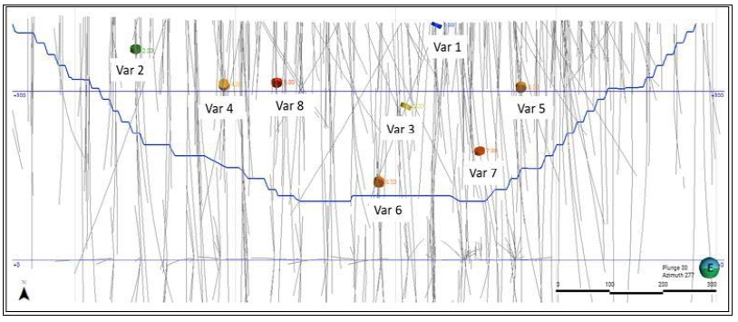
Source: Seabridge Gold, 2023
| 13.3.1 | SGS-Lakefield Program (2010/2011) |
2010/2011 Lakefield program consisted of seven composite
samples generated from diamond drill cores for the various mineralization zones of the Courageous Lake or the FAT deposit. The sample
preparation is described as follows:
| ● | Zone 4 drill core interval samples were grouped into three composites: Zone
4 Composite, Low Au Composite, and High Au Composite. |
| ● | Zone 3 drill core interval samples were combined to create Zone 3 Composite. |
| ● | Zone 5 drill core interval samples were combined to create Zone 5 Composite. |
| ● | Samples drill core interval from Zones 2, 6, 7, 9, and 14 were combined to
create Combined Zone Composite (CZ). |
| ● | The Master Composite (MC) was created from the zone composite samples from
all eight zones (2, 3, 4, 5, 6, 7, 9, and 14). |
| Courageous Lake Project | Page 119 |
| Pre-feasibility Study and Preliminary Economic Assessment NI 43-101 Technical Report | January 5, 2024 |
The head assay results of the composites are provided in
Table 13-2.
| Table 13-2: | Head Assay Data – SGS (2010/2011) |
| Composite |
Au
(g/t) |
Ag
(g/t) |
S-2
(%) |
ST
(%) |
Fe
(%) |
As
(%) |
C
(%) |
Corg
(%) |
| Master |
2.13 |
0.60 |
0.58 |
0.65 |
2.16 |
0.37 |
0.81 |
0.04 |
| CZ |
2.35 |
1.90 |
0.80 |
0.81 |
3.31 |
0.54 |
0.85 |
0.03 |
| Zone 3 |
2.94 |
0.70 |
0.57 |
0.62 |
2.22 |
0.42 |
0.92 |
0.04 |
| Zone 4 |
2.33 |
1.50 |
0.44 |
0.50 |
1.86 |
0.34 |
0.79 |
0.03 |
| Zone 5 |
2.45 |
0.70 |
0.47 |
0.58 |
2.00 |
0.33 |
0.62 |
0.02 |
| Low Au |
1.24 |
1.80 |
0.38 |
0.38 |
2.00 |
0.26 |
0.80 |
0.03 |
| High Au |
4.21 |
3.20 |
0.53 |
0.61 |
1.77 |
0.50 |
0.65 |
0.03 |
Gold grades ranged from 1.24 to 4.21
g/t Au with an average grade of 2.52 g/t Au. The arsenic contents ranged from 0.26% to 0.54% with an average of 0.39%. The sulfur grades
ranged from 0.38% to 0.80% and the average was 0.54%. Gold grades were similar to those reported in the mine plan, but sulfur and arsenic
grades in test work were higher than the grades expected in the mine plan.
The most recent test program was completed
by ALS Kamloops in 2023 which included eight variability samples representing a range of grade, depth, and zone parameters from eight
drill cores of the Courageous Lake deposit. A head assay for each of the eight samples was determined for gold, silver, sulfur, arsenic,
carbon, iron, calcium and other major, minor, and trace elements. Variability samples consisted of discrete samples comprised of a continuous
drill core interval, yielding sufficient mass for the planned comminution and flotation testwork. The head assay results of the samples
are given in Table 13-3.
| Table 13-3: | Head Assay Data – ALS (2023) |
| Zone |
Sample
ID |
Au
(g/t) |
Ag
(g/t) |
S
(%) |
As
(%) |
C
(%) |
Fe
(%) |
Ca
(%) |
Hg,
% |
| 3 |
Var 1 |
5.26 |
0.47 |
0.73 |
0.63 |
0.96 |
1.83 |
1.75 |
<1 |
| 3 |
Var 2 |
3.61 |
1.19 |
1.18 |
0.62 |
0.96 |
2.67 |
2.09 |
<1 |
| 3 |
Var 3 |
4.98 |
0.43 |
0.52 |
0.72 |
0.89 |
1.58 |
1.67 |
<1 |
| 5 |
Var 4 |
2.18 |
0.66 |
0.88 |
0.48 |
0.78 |
1.63 |
2.12 |
<1 |
| 4 |
Var 5 |
1.83 |
0.46 |
0.77 |
0.38 |
1.18 |
2.13 |
3.15 |
<1 |
| 4 |
Var 6 |
0.55 |
0.221 |
0.27 |
0.14 |
0.52 |
1.95 |
1.63 |
<1 |
| 4 |
Var 7 |
3.86 |
0.89 |
0.72 |
0.59 |
0.65 |
1.94 |
1.69 |
<1 |
| 5 |
Var 8 |
2.44 |
0.29 |
0.51 |
0.37 |
0.65 |
1.46 |
1.86 |
<1 |
Note:
Gold grades ranged
from 0.55 to 5.26 g/t Au with an average grade of 3.09 g/t Au. Silver grades varied from 0.22 to 1.19 g/t Ag with an average grade
of 0.58 g/t Ag. The arsenic contents ranged from 0.14% to 0.72% with an average of 0.49%. The sulfur contents ranged from
0.27% to 1.18% and the average was 0.70%. Gold and silver grades were similar to those reported in the mine plan, but sulfur and arsenic
grades in test work were higher than the grades expected in the mine plan.
| Courageous Lake Project | Page 120 |
| Pre-feasibility Study and Preliminary Economic Assessment NI 43-101 Technical Report | January 5, 2024 |
| 13.4.1 | SGS Program (2003/2004) |
SGS-Lakefield carried out a mineralogical
analysis on Composite Zone 345-1. The study showed that the dominant sulphides in the sample were arsenopyrite (<5-350 µm), pyrite
(5-350 µm), marcasite (20-350 µm), and pyrrhotite (5-350 µm). Total sulfur content averaged at 0.52%. The gold occurred
as liberated gold, or gold associated with sulfides and silicate/sulphide binaries. Gold grain sizes ranged from sub-microscopic size
to 70 µm and gold grains were liberated, attached to sulphides and locked in sulphide minerals (mainly arsenopyrite), indicating
the refractory nature of the deposit. It appeared that the degree of the sulphide oxidation was very low.
G&T mineralogical analysis indicated
that 1.8% of the minerals in the tested MC occurred as sulfide minerals. The dominant sulfides were arsenopyrite and pyrrhotite, both
of which represented 0.7% of the total mineralization weight. Pyrite content was 0.4%. At the grind size of 80% passing 165 µm,
43% to 54% of sulfides were present as liberated grains.
Mineral composition analyses were completed
on the eight variability samples using QEMSCAN. Composition data and sulfur deportment data are reported in Table 13-4 and Table 13-5,
respectively.
| Table 13-4: | Mineral Composition Data – ALS
2023 Variability Samples |
| Minerals |
Var
1 |
Var
2 |
Var
3 |
Var
4 |
Var
5 |
Var
6 |
Var
7 |
Var
8 |
| Sizing (µm K80) |
97 |
100 |
102 |
96 |
79 |
102 |
86 |
100 |
| Copper Sulfides |
<0.1 |
<0.1 |
<0.1 |
<0.1 |
<0.1 |
<0.1 |
<0.1 |
<0.1 |
| Pyrite |
0.5 |
0.8 |
0.2 |
1.5 |
0.8 |
0.1 |
0.6 |
0.2 |
| Pyrrhotite |
0.3 |
1.0 |
0.1 |
0.1 |
0.4 |
0.3 |
0.3 |
0.6 |
| Arsenopyrite |
1.4 |
1.0 |
1.4 |
1.1 |
0.6 |
0.3 |
0.9 |
0.7 |
| Other Sulfide Minerals |
<0.1 |
<0.1 |
<0.1 |
<0.1 |
<0.1 |
<0.1 |
<0.1 |
0.0 |
| Iron Oxides |
0.2 |
0.4 |
0.3 |
0.1 |
0.1 |
0.2 |
0.2 |
0.2 |
| Quartz |
45.1 |
38.4 |
65.5 |
51.3 |
44.7 |
37.2 |
52.6 |
47.2 |
| Feldspars |
17.5 |
33.6 |
12.0 |
14.7 |
23.2 |
43.7 |
21.8 |
26.9 |
| Micas |
24.6 |
14.9 |
12.1 |
21.6 |
17.8 |
10.8 |
14.3 |
16.3 |
| Chlorite |
0.8 |
0.9 |
1.9 |
1.7 |
1.1 |
2.9 |
3.2 |
1.3 |
| Courageous Lake Project | Page 121 |
| Pre-feasibility Study and Preliminary Economic Assessment NI 43-101 Technical Report | January 5, 2024 |
| Minerals |
Var
1 |
Var
2 |
Var
3 |
Var
4 |
Var
5 |
Var
6 |
Var
7 |
Var
8 |
| Calcium Carbonates |
8.0 |
7.4 |
5.6 |
5.4 |
9.6 |
3.1 |
4.5 |
4.9 |
| Titanium Minerals |
0.2 |
0.4 |
0.2 |
0.3 |
0.3 |
0.3 |
0.2 |
0.3 |
| Kaolinite (clay) |
0.5 |
0.3 |
0.2 |
1.1 |
0.8 |
0.5 |
0.6 |
0.8 |
| Apatite |
0.2 |
0.3 |
0.2 |
0.3 |
0.2 |
0.1 |
0.2 |
0.2 |
| Others |
0.5 |
0.6 |
0.4 |
0.9 |
0.5 |
0.4 |
0.3 |
0.4 |
| Total |
100 |
100 |
100 |
100 |
100 |
100 |
100 |
100 |
Modal mineralogy indicates that the
predominant sulfide minerals contained across the samples were arsenopyrite and pyrite. The gangue mineralogy was dominated by quartz,
micas, feldspar, and calcium carbonate.
| Table 13-5: | Sulfur Deportment Data – ALS 2023 Variability Samples |
| Minerals |
Var
1 |
Var
2 |
Var
3 |
Var
4 |
Var
5 |
Var
6 |
Var
7 |
Var
8 |
| Copper Sulfides |
0.1 |
<0.1 |
0.1 |
0.1 |
0.2 |
0.8 |
2.1 |
0.2 |
| Pyrite |
40.6 |
42.5 |
28.1 |
75.7 |
55.8 |
18.4 |
45.9 |
23.0 |
| Pyrrhotite |
16.9 |
38.5 |
8.0 |
3.4 |
27.9 |
56.4 |
24.5 |
48.8 |
| Arsenopyrite |
42.2 |
18.9 |
63.6 |
20.3 |
15.9 |
24.0 |
27.5 |
27.9 |
| Other Sulfide Minerals |
0.1 |
0.1 |
0.1 |
0.5 |
0.2 |
0.2 |
<0.1 |
0.1 |
| Sulphate Minerals |
0.1 |
<0.1 |
0.1 |
<0.1 |
<0.1 |
0.1 |
<0.1 |
0.1 |
| Total |
100 |
100 |
100 |
100 |
100 |
100 |
100 |
100 |
The ALS test results confirmed that the principal sulfide
minerals were pyrite, arsenopyrite, and pyrrhotite.
A series of comminution tests were completed
on the Courageous Lake mineral deposit to characterize hardness/grindability of the deposit; results are presented in Table 13-6. The
comminution tests were conducted at laboratories of SGS, G&T, ALS. These include crushing and grinding work indices, SMC test parameters
A x b, and abrasion indices.
| Table 13-6: | Comminution Data |
| Sample
Program |
A
x b |
Abrasion
Index (g) |
Rod
Mill Wi
(kWh/t) |
Ball
Mill Wi
(kWh/t) |
Comments |
| SGS 2003 |
29.7 |
0.192 |
18.1 |
15.5 |
|
|
G&T 2007 |
- |
- |
- |
16.2 |
Master Composite (aged sample) |
| - |
- |
- |
17.3 |
Master Composite (fresh sample) |
| - |
- |
- |
16.1 |
Master Composite (aged & fresh 25/15 blend) |
| Courageous Lake Project | Page 122 |
| Pre-feasibility Study and Preliminary Economic Assessment NI 43-101 Technical Report | January 5, 2024 |
The results indicate that the ore is
very competent with respect to breakage in a SAG mill. The Bond ball mill work index results suggest that the material is of moderate
hardness with respect to grinding in a ball mill. All BMWi tests were completed at a closing screen size of 106 µm. The ball mill
work index (BMWi) results from ALS 2023 test program are summarized in Table 13-7.
| Table 13-7: | Comminution Data – ALS 2023
Test Program |
| Sample
ID |
Zone |
Ball
Mill Wi (kWh/t) |
| Var 1 |
3 |
11.9 |
| Var 2 |
3 |
14.9 |
| Var 3 |
3 |
14.0 |
| Var 4 |
5 |
14.1 |
| Var 5 |
4 |
14.6 |
| Var 6 |
4 |
18.1 |
| Var 7 |
4 |
14.5 |
| Var 8 |
5 |
15.3 |
| 13.6 | Pre-concentration (Ore Sorting) |
In 2018, Tomra Sorting Mining conducted
initial pre-concentration tests on seven drill core samples via XRT technology using a sorting machine with dual XRT sensors and a belt
feeding system to examine the possibility of sorting ore-type material (gold bearing) from gangue-type material based on differences in
density. The results show that the XRT sorting system is able to detect sulfide material in the provided split drill core samples from
the Courageous Lake deposit.
| 13.7 | Gravity Concentration |
Gravity concentration tests were conducted
by G&T in 2007 and 2012, and SGS-Lakefield in 2003/2004 and 2011 test programs. The results of these tests indicate that the material
did not exhibit a strong response to gold recovery through gravity concentration. The gravity concentration trials involved a combination
of centrifugal gravity concentration, followed by either panning or tabling. The G&T experiments revealed that, with panning, the
centrifugal concentrate could achieve an upgrade to 102 g/t Au, with a recovery rate of 16%.
In Courageous Lake ore refractory gold
is believed to be associated with iron sulphides, primarily pyrite and arsenopyrite. The goals of these tests are to determine the floatability
of the sulphides, and the recovery of Au and Ag in the sulphide concentrate. The ability to recover Au and Ag in the sulfide concentrate
reduces the volume of material to be treated. All the test programs indicated that the mineral samples responded well to bulk sulfide
flotation.
Historical testwork conducted various
flotation optimization programs evaluating primary grind size, reagents addition rate, and pulp pH.
The SGS 2010/2011 test
work included variability testing conducted on the samples generated from the various mineralization zones. The range of primary
grind sizes tested was P80 of 90 µm to 143 µm. The test work showed improved gold recovery with target primary grind
size of 80% passing of nominal 100 µm. Upon completion of the grind sensitivity testwork a primary grind of 100 µm was
selected as the optimum. The test program indicated that adjusting the slurry pH with sulphuric acid from a natural pH of 8.0 to pH
7 and 6 did not improve gold recovery. The 2010/2011 test work used 105 g/t PAX plus 20 g/t A208 for the locked cycle tests and
showed that gold recovery improved when CuSO4 was added to
activate the sulphides. The rougher flotation test results at the target 100 µm grind size are shown in Table 13-8.
| Courageous Lake Project | Page 123 |
| Pre-feasibility Study and Preliminary Economic Assessment NI 43-101 Technical Report | January 5, 2024 |
| Table 13-8: | Rougher Flotation Test Data –
SGS |
| Test |
Feed
Grade |
Rougher
Mass
Pull (%) |
Rougher
Recovery (%) |
Rougher
Concentrate Grade |
Au
(g/t ) |
S-2
(%) |
Fe
(%) |
As
(%) |
C
(%) |
Au |
S-2 |
Fe |
As |
C |
Au
(g/t) |
S-2
(%) |
Fe
(%) |
As
(%) |
C
(%) |
| Zone 3 – F1 batch cleaner test |
3.0 |
0.7 |
2.3 |
0.4 |
1.0 |
12.3 |
90.1 |
90.1 |
44.5 |
89.3 |
13.9 |
21.9 |
5.2 |
8.3 |
3.1 |
1.1 |
| Zone 5 – F1 batch cleaner test |
2.2 |
0.6 |
2.1 |
0.3 |
0.7 |
12.2 |
92.3 |
91.2 |
44.4 |
92.9 |
14.0 |
16.4 |
4.5 |
7.6 |
2.5 |
0.8 |
| Low Au – F1 Zone 4 batch cleaner test |
1.1 |
0.5 |
2.1 |
0.3 |
0.8 |
10.4 |
92.4 |
90.3 |
35.6 |
92.7 |
11.8 |
9.5 |
4.0 |
7.2 |
2.2 |
0.9 |
| High Au – F1 Zone 4 batch cleaner test |
4.2 |
0.7 |
1.8 |
0.5 |
0.7 |
11.1 |
92.7 |
93.2 |
51.0 |
92.5 |
11.5 |
33.8 |
5.5 |
8.7 |
4.2 |
0.7 |
| Locked Cycle Test on Zone 3 Composite |
3.0 |
0.7 |
2.4 |
0.4 |
0.9 |
8.5 |
90.2 |
93.1 |
41.5 |
91.0 |
10.6 |
31.4 |
7.3 |
11.5 |
4.7 |
1.2 |
| Locked Cycle Test on Zone 4 Composite |
2.3 |
0.6 |
2.2 |
0.4 |
0.8 |
13.8 |
90.9 |
92.0 |
39.2 |
92.5 |
11.8 |
14.9 |
3.8 |
6.3 |
2.4 |
0.7 |
| Locked Cycle Test on Zone 5 Composite |
2.3 |
0.6 |
2.0 |
0.3 |
0.6 |
13.0 |
92.0 |
92.2 |
39.5 |
93.3 |
12.7 |
16.1 |
4.1 |
6.1 |
2.5 |
0.6 |
| Locked Cycle Test on Zone 4 Low Au Composite |
1.8 |
0.7 |
3.2 |
0.4 |
1.2 |
11.6 |
91.5 |
90.6 |
62.8 |
92.8 |
13.2 |
13.9 |
5.5 |
10.2 |
3.0 |
1.4 |
| Locked Cycle Test on Zone 4 High Au Composite |
5.1 |
0.9 |
2.3 |
0.6 |
0.8 |
16.0 |
93.0 |
93.8 |
52.3 |
93.0 |
17.5 |
29.4 |
5.0 |
7.5 |
3.6 |
0.9 |
The test results indicate that, on average,
92% of the gold and 92% of sulfur reports to the rougher flotation concentrate with an average mass pull of 12%.
| Courageous Lake Project | Page 124 |
| Pre-feasibility Study and Preliminary Economic Assessment NI 43-101 Technical Report | January 5, 2024 |
The most recent flotation testing was
to confirm the ore response using test conditions established from 2011 SGS test work with variability samples representing the target
mining area and a range of grade, depth, and zone parameters.
The flotation test conditions were selected based on the
SGS 2011 test program and included:
| ● | primary grind size of 100 µm |
| ● | reagents: potassium amyl xanthate (PAX), A208, copper sulphate (CuSO4) |
| ● | single-stage cleaning of bulk rougher concentrate. |
| 13.8.2.1 | Effect of Primary Grind Size |
Rougher kinetic tests were conducted
at varying target grind sizes ranging from 97 to 150 µm to evaluate the effect of primary grind size on gold recovery. The test
results presented in Figure 13-2 show that gold recovery generally improves with decreased primary grind size. The primary grind size
of 80% passing at 100 µm was selected for flowsheet design.
| Figure 13-2: | Effect of the Grind Size –
ALS 2023 Variability Samples |
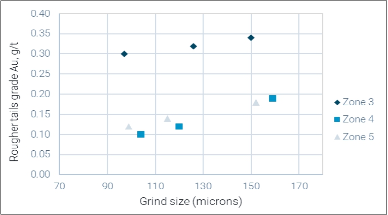
Source: Ausenco, 2023
| Courageous Lake Project | Page 125 |
| Pre-feasibility Study and Preliminary Economic Assessment NI 43-101 Technical Report | January 5, 2024 |
| 13.8.2.2 | Flotation Kinetics |
Kinetics plots for the response of gold
recovery over time of flotation for eight variability samples from 2023 ALS test work are shown in Figure 13-3. The results show average
laboratory flotation time is around eight minutes for it to complete flotation, attaining 95% recovery for gold.
| Figure 13-3: | Gold Recovery vs Time Plot – ALS 2023
Variability Samples |
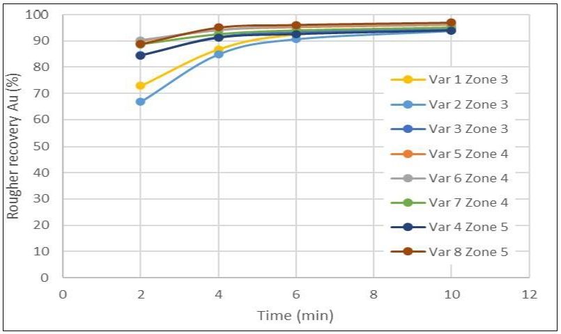
Source: Ausenco, 2023
| 13.8.2.3 | Flotation Recovery |
The flotation results of
ALS 2023 variability samples are summarized in Table 13-9. The average of eight variability samples, 95% of the gold and 94% of sulfur
reports to the rougher flotation concentrate with an average gold grade of 36 g/t Au and an average mass pull of 8.5%. Tests Var 5 and
Var 7 did not meet target grind size of 100 µm.
| Courageous Lake Project | Page 126 |
| Pre-feasibility Study and Preliminary Economic Assessment NI 43-101 Technical Report | January 5, 2024 |
| Table 13-9: | Rougher Flotation Recovery Data – ALS 2023 |
Sample
ID |
Primary
Grind Size
(µm) |
Rougher Mass
(%) |
Rougher
Concentrate Distribution |
Rougher
Concentrate Grade |
| Au |
Ag |
S |
As |
C |
Fe |
Au
(g/t) |
Ag
(g/t) |
S2-
(%) |
As
(%) |
C
(%) |
Fe
(%) |
| Var 1 |
97 |
7.4 |
93.8 |
90.1 |
95.0 |
96.5 |
6.0 |
50.5 |
66.7 |
5.7 |
9.4 |
8.2 |
0.8 |
12.5 |
| Var 2 |
100 |
9.6 |
95.5 |
96.2 |
93.9 |
96.2 |
7.8 |
58.4 |
36.0 |
11.9 |
11.6 |
6.3 |
0.8 |
16.3 |
| Var 3 |
102 |
5.2 |
93.4 |
89.1 |
94.6 |
97.0 |
4.9 |
51.6 |
72.4 |
5.9 |
7.6 |
10.9 |
0.7 |
12.7 |
| Var 4 |
96 |
13.1 |
94.0 |
93.4 |
96.0 |
96.0 |
11.3 |
63.2 |
15.7 |
4.7 |
6.4 |
3.5 |
0.7 |
7.9 |
| Var 5 |
79 |
10.0 |
96.1 |
90.2 |
96.5 |
97.6 |
8.0 |
48.5 |
17.6 |
4.1 |
7.5 |
3.7 |
1.0 |
10.4 |
| Var 6 |
102 |
5.0 |
96.6 |
78.0 |
89.5 |
98.7 |
5.0 |
24.6 |
10.6 |
3.3 |
4.8 |
2.8 |
0.5 |
9.5 |
| Var 7 |
86 |
8.4 |
95.0 |
79.4 |
96.2 |
96.6 |
6.5 |
49.1 |
43.7 |
8.4 |
8.2 |
6.8 |
0.5 |
11.4 |
| Var 8 |
100 |
9.6 |
97.0 |
84.6 |
93.0 |
98.8 |
8.5 |
54.9 |
24.7 |
2.6 |
5.0 |
3.8 |
0.6 |
8.4 |
All test programs conducted single-stage
and two-stage cleaner flotation in an effort to improve concentrate grade. The test results indicated that the rougher bulk concentrates
can be upgraded by one stage of cleaner flotation with a 3% loss of gold into the cleaner flotation tailing.
The 2003/2004 test program conducted
two cleaner flotation tests on the Zone Composite sample to improve the final concentrate grade by using a more selective collector A3894.
Results demonstrated single-stage cleaning could upgrade the rougher flotation concentrate from 12 g/t Au to 61 g/t Au and to 93 g/t Au
with two stages of cleaning. This upgrade came with a loss in gold reporting to the concentrates decreasing from 92% in the rougher flotation
concentrate to 87% in the first cleaner flotation concentrate, and to 80% in the second cleaner flotation concentrate. Sulfur grade in
the rougher flotation concentrate was concentrated from 3.6% to 17.4% with one stage of cleaner flotation and to 26% with two-stage cleaning.
The 2010/2011 test program further investigated
cleaning of the concentrate with results showing good upgrading efficiencies for rougher flotation concentrates, with gold recovery at
the first cleaner flotation stage of averaging at 96%. The test indicated that single-stage cleaning could upgrade the rougher flotation
concentrate from an average of 21 g/t Au to an average of 52 g/t Au and from average 5.% to an average 13% sulfur.
| Courageous Lake Project | Page 127 |
| Pre-feasibility Study and Preliminary Economic Assessment NI 43-101 Technical Report | January 5, 2024 |
| Table 13-10: | Cleaner Flotation Test Data – SGS 2010/2011 |
Test |
Cleaner
Mass Pull
(%) |
Cleaner
Concentrate Distribution (%) |
Cleaner
Concentrate Grade |
| Au |
S2- |
Fe |
As |
C |
Au
(g/t) |
S2-
(%) |
Fe
(%) |
As
(%) |
C
(%) |
| Zone 3 – F1 batch cleaner test |
4.8 |
97.4 |
96.1 |
84.7 |
96.9 |
36.0 |
54.8 |
12.7 |
18.0 |
7.7 |
1.0 |
| Zone 5 – F1 batch cleaner test |
4.4 |
97.1 |
96.5 |
83.8 |
96.9 |
31.4 |
44.2 |
12.0 |
17.8 |
6.8 |
0.7 |
|
Low Au – F1 Zone 4 batch cleaner
test |
3.7 |
97.4 |
97.6 |
81.2 |
96.7 |
32.2 |
26.0 |
11.1 |
16.6 |
6.0 |
0.8 |
|
High Au – F1 Zone 4 batch cleaner
test |
4.7 |
97.1 |
98.1 |
88.8 |
97.0 |
35.7 |
77.6 |
12.7 |
18.2 |
9.6 |
0.6 |
|
Locked Cycle Test on Zone 3
Composite |
3.5 |
95.2 |
96.1 |
86.0 |
93.8 |
37.7 |
72.1 |
17.0 |
23.8 |
10.6 |
1.0 |
|
Locked Cycle Test on Zone 4
Composite |
4.3 |
95.8 |
95.9 |
84.7 |
95.0 |
39.0 |
45.5 |
11.5 |
17.0 |
7.4 |
0.8 |
|
Locked Cycle Test on Zone 5
Composite |
3.8 |
95.3 |
96.3 |
83.8 |
95.2 |
33.1 |
53.2 |
13.6 |
17.6 |
8.1 |
0.7 |
|
Locked Cycle Test on Zone 4 Low Au
Composite |
4.6 |
95.7 |
95.6 |
47.5 |
95.3 |
38.6 |
33.4 |
13.2 |
20.5 |
7.2 |
1.4 |
|
Locked Cycle Test on Zone 4 High Au
Composite |
7.2 |
95.5 |
96.4 |
83.6 |
95.4 |
42.9 |
62.8 |
10.7 |
14.1 |
7.8 |
0.9 |
The 2023 ALS test program conducted
cleaner flotation tests on eight variability samples. The rougher concentrate and cleaner concentrate grades are presented in Table 13-11.
The gold concentrate grade improved by an average upgrade ratio of two after a single stage of cleaning. The average rougher concentrate
grade of eight variability samples was improved from 41 g/t to 73 g/t Au with single-stage cleaning. The average sulfur grade was upgraded
from 8.5% to 16%. The average gold recovery after cleaning the rougher concentrate was 92%.
| Table 13-11: | Cleaner Flotation Variability Test Data – ALS
2023 |
Zone |
Sample
ID |
Primary
Grind Size (µm) |
Rougher
Concentrate
Grade |
Cleaner
Mass Pull (%) |
Cleaner
Recovery
(%) |
Cleaner
Concentrate Grade |
Au
(g/t) |
Ag
(g/t) |
S
(%) |
Au |
Ag |
S |
Au
(g/t) |
Ag
(g/t) |
S
(%) |
| 3 |
Var 1 |
97 |
47.9 |
5.6 |
6.7 |
4.2 |
89.9 |
43.9 |
90.0 |
114.1 |
8.0 |
16.1 |
| 3 |
Var 2 |
100 |
31.7 |
11.0 |
10.1 |
6.6 |
92.0 |
84.1 |
87.8 |
52.3 |
18.0 |
16.5 |
| 3 |
Var 3 |
102 |
84.2 |
6.7 |
8.8 |
3.0 |
90.4 |
85.8 |
90.5 |
84.2 |
6.7 |
8.8 |
| 4 |
Var 5 |
124 |
22.5 |
5.3 |
8.5 |
3.9 |
93.2 |
84.5 |
91.9 |
42.6 |
9.0 |
17.6 |
| 4 |
Var 6 |
102 |
22.4 |
4.9 |
9.3 |
1.5 |
93.0 |
65.8 |
85.6 |
35.8 |
8.0 |
16.1 |
| 4 |
Var 7 |
116 |
13.1 |
3.2 |
6.1 |
3.6 |
93.4 |
87.4 |
90.6 |
107.0 |
20.0 |
17.9 |
| 5 |
Var 4 |
96 |
61.2 |
12.1 |
10.6 |
5.4 |
93.0 |
88.0 |
93.4 |
39.4 |
9.0 |
15.0 |
| 5 |
Var 8 |
100 |
43.6 |
4.2 |
8.2 |
2.3 |
94.1 |
77.7 |
90.0 |
110.2 |
10.0 |
20.3 |
| Courageous Lake Project | Page 128 |
| Pre-feasibility Study and Preliminary Economic Assessment NI 43-101 Technical Report | January 5, 2024 |
Direct cyanidation of flotation concentrate
testwork is historical, yielding poor results with Au recoveries ranging from 24% to 42% after 48 hours of leaching with results shown
in Table 13-12. The 2003/2004 SGS-Lakefield test program indicated 24% of the gold, on average, can be extracted from the concentrates
at the grind size of 80% passing 23 µm. A slight improvement in gold extraction was noticed when concentrate was further reground
to 80% passing 13 µm as shown from the test work conducted by G&T in 2007. The 2011 SGS-Lakefield direct cyanidation tests achieved
28% gold recovery after 48 hours of leaching. The test results indicate concentrates are refractory to direct cyanidation.
| Table 13-12: | Gold Extraction by Direct Cyanide Leaching of Flotation
Concentrate – Historical Tests |
| Sample |
Test
Program |
Grind
Size P80
(µm) |
Head
Assay
(g/t
Au) |
Retention
Time
(h) |
Gold
Recovery
% |
| Concentrate – F12 |
2003/2004 SGS-Lakefield |
23 |
19.2 |
48 |
24 |
| Concentrate – F4 |
2007 G&T |
13 |
7.7 |
48 |
32 |
| Concentrate
– F121 |
2007 G&T |
10 |
7.7 |
48 |
42 |
| Blended Concentrate |
2011 SGS-Lakefield |
43 |
33.1 |
48 |
28 |
Note:
| 1. | Caustic leach for 16 hours prior to cyanidation. |
| 13.10.1 | Cyanide Leach of Flotation Tail |
In 2023 ALS test program, flotation
tails were directly leached with cyanide for 24 hours. The results are shown in Table 13-13 showing, on average, 45% of gold can be recovered
from the tails; however, this option was evaluated as uneconomic for the selected flowsheet.
| Table 13-13: | Gold Extraction by Direct Cyanide
Leaching of Flotation Concentrate – Historical Tests |
Zone |
Sample
ID |
Primary
Grind size
(µm) |
Feed Grade
(calculated)
Au (g/t) |
Liquor
Grade
Au
(g/t) |
Residue
Grade Au
(g/t) |
Au
Extraction1
(%) |
NaCN
Consumption
(kg/t) |
CaO
Consumption
(kg/t) |
| 3 |
Var 1 |
97 |
0.34 |
0.11 |
0.17 |
49.31 |
0.08 |
0.38 |
| 3 |
Var 2 |
100 |
0.16 |
0.05 |
0.08 |
48.42 |
0.09 |
0.41 |
| 3 |
Var 3 |
102 |
0.36 |
0.14 |
0.15 |
58.50 |
0.09 |
0.33 |
| 5 |
Var 4 |
96 |
0.14 |
0.03 |
0.10 |
32.21 |
0.09 |
0.30 |
| 4 |
Var 7 |
86 |
0.20 |
0.05 |
0.13 |
37.53 |
0.06 |
0.32 |
Note:
| 1. | Based on calculated feed grade. |
| Courageous Lake Project | Page 129 |
| Pre-feasibility Study and Preliminary Economic Assessment NI 43-101 Technical Report | January 5, 2024 |
Several oxidation tests were conducted
on Courageous Lake mineralization. In the 2003/2004 test program, Lakefield conducted eight batch POX tests and three semi-continuous
POX tests on the flotation concentrate from Zone 345-1 composite. Samples were pressure oxidized at an oxygen partial pressure of 100
psi and a temperature of 225°C. The POX feeds were pre-acidulated with sulfuric acid at pH 3 for one hour to decompose carbonate minerals
prior to the POX stage, otherwise CO2 emission in the autoclave would lower oxidation efficiency and oxygen utilization. The oxidation
retention time varied from 45 to 90 minutes. Gold extraction by cyanidation was 42.6%, 82.5% and 98.5% at sulphide oxidations of 45%,
67% and 98% respectively.
The 2010/2011 SGS-Lakefield test program
included POX tests conducted at lower temperatures ranging from 190°C to 220°C, retention time of 120 min, and partial oxygen
pressure of 100 psi. The POX feeds were pre-leached with sulfuric acid for one hour to maintain a pH of 1.8. Blend 1 sample consisted
of MC cleaner concentrate (37.5%) and cleaner scavenger tails (62.5%). Blend 1 head elemental analysis is summarized in Table 13-14.
| Table 13-14: | Blend 1 Head Analysis |
| Element |
Units |
Blend
1 |
| Au |
g/t |
34.6 |
| Ag |
g/t |
11.7 |
| As |
% |
5.1 |
| Fe |
% |
13.0 |
| S= |
% |
8.9 |
| S |
% |
9.1 |
| C(t) |
% |
0.9 |
| C(g) |
% |
0.0 |
| TOC leco |
% |
0.2 |
| CO3 |
% |
3.9 |
| Al |
g/t |
56000.0 |
| Ba |
g/t |
190.0 |
| Be |
g/t |
0.9 |
| Bi |
g/t |
20.0 |
| Ca |
g/t |
25600.0 |
| Cd |
g/t |
<10 |
| Co |
g/t |
86.0 |
| Cr |
g/t |
576.0 |
| Cu |
g/t |
897.0 |
| K |
g/t |
20100.0 |
| Li |
g/t |
6280.0 |
| Mn |
g/t |
675.0 |
| Mo |
g/t |
6.0 |
| Courageous Lake Project | Page 130 |
| Pre-feasibility Study and Preliminary Economic Assessment NI 43-101 Technical Report | January 5, 2024 |
| Element |
Units |
Blend
1 |
| Na |
g/t |
10200.0 |
| Ni |
g/t |
78.0 |
| P |
g/t |
287.0 |
| Pb |
g/t |
59.0 |
| Sb |
g/t |
82.0 |
| Se |
g/t |
<30 |
| Sn |
g/t |
<20 |
| Sr |
g/t |
108.0 |
| Ti |
g/t |
1930.0 |
| Tl |
g/t |
30.0 |
| U |
g/t |
20.0 |
| V |
g/t |
32.0 |
| Y |
g/t |
9.0 |
| Zn |
g/t |
434.0 |
| Cl |
g/t |
88.0 |
| F |
% |
0.0 |
The 2010/2011 SGS-Lakefield test program
included POX tests conducted at lower temperatures ranging from 190°C to 220°C, retention time of 120 min, and partial oxygen
pressure of 100 psi. The POX test conditions are listed in Table 13-15. The results from the 2010/2011 SGS POX test program are summarized
in Table 13-16.
| Table 13-15: | POX Test Conditions – SGS 2011 |
Test
ID |
Sample
ID |
Pre-acidulation |
POX
Conditions |
Grind
Size P80
(µm) |
Pulp
Density
(w/w%) |
pH |
Acid
Addition
(kg/t) |
Temperature
(°C) |
POX
Time
(min) |
Hot
Cure
(min) |
| РОХ1 |
BIend 1 |
43 |
34 |
1.8 |
91 |
190 |
120 |
n/a |
| РОХ2 |
BIend 1 |
43 |
34 |
1.8 |
92 |
200 |
120 |
n/a |
| РОХ3 |
BIend 1 |
43 |
34 |
1.8 |
92 |
210 |
120 |
n/a |
| РОХ4 |
BIend 1 |
43 |
34 |
1.8 |
92 |
220 |
120 |
n/a |
| РОХ5 |
BIend 1 |
43 |
34 |
1.8 |
92 |
210 |
120 |
240 |
| РОХ6 |
BIend 1 |
43 |
34 |
1.8 |
92 |
200 |
120 |
n/a |
| РОХ7 |
BIend 1 |
43 |
34 |
1.8 |
86 |
200 |
120 |
n/a |
| РОХ8 |
BIend 1 |
18 |
34 |
1.8 |
92 |
200 |
120 |
n/a |
| РОХ9 |
BIend 1 |
43 |
34 |
5.2 |
45 |
200 |
120 |
n/a |
| РОХ10 |
BIend 1 |
43 |
34 |
1.8 |
90 |
200 |
120 |
n/a |
|
РОХ11 |
LСТ 2
Combined Sulphide |
23 |
29 |
1.8 |
76 |
200 |
120 |
n/a |
| Courageous Lake Project | Page 131 |
| Pre-feasibility Study and Preliminary Economic Assessment NI 43-101 Technical Report | January 5, 2024 |
| |
Sample |
Pre-acidulation |
POX
Conditions |
| Test
ID |
ID |
Grind
Size P80 (µm) |
Pulp
Density
(w/w%) |
|
Acid
Addition
(kg/t) |
Temperature
(°C) |
POX
Time
(min) |
Hot
Cure
(min) |
| |
pH |
| |
Соnc
(CZ Zone) |
|
|
|
|
|
|
|
|
РОХ12 |
LCT З
Combined SuIphide
Соnc |
23 |
34 |
1.8 |
96 |
200 |
120 |
n/a |
|
РОХ13 |
LCT 5
Combined SuIphide
Соnc |
22 |
34 |
1.8 |
63 |
200 |
120 |
n/a |
| РОХ14 |
LСТ 10 Ro
conc |
21 |
30 |
1.8 |
75 |
200 |
120 |
n/a |
| РОХ15 |
LCT 10 To
Conc |
21 |
30 |
1.8 |
75 |
220 |
120 |
n/a |
| Table 13-16: | POX and Cyanidation Test Results – SGS 2011 |
Test
ID |
Sample
ID |
Reagent
Consumption
(kg/t
POX Feed) |
Au
Extraction
(%) |
Ag
Extraction
(%) |
Head
Grade
|
Temperature
(°C) |
| NaCN |
CaO |
8
h |
24
h |
48
h |
24
h |
48
h |
Au |
Ag |
S-2 |
| No POX |
Blend 1 |
4.5 |
1.7 |
16.1 |
22.8 |
27.5 |
- |
78.5 |
32.6 |
10.7 |
8.9 |
- |
| POX 1 |
Blend 1 |
0.2 |
1.4 |
92.4 |
94.5 |
95.1 |
- |
32.6 |
29.2 |
11.6 |
8.9 |
190 |
| POX 2 |
Blend 1 |
0.3 |
1.3 |
95.0 |
97 |
96.8 |
- |
28.5 |
29.3 |
12.7 |
8.9 |
200 |
| POX 3 |
Blend 1 |
0.2 |
1.4 |
95.2 |
95.8 |
97.6 |
- |
27.1 |
30.2 |
13.2 |
8.9 |
210 |
| POX 4 |
Blend 1 |
0.3 |
3.3 |
95.6 |
97.1 |
97.1 |
- |
22.2 |
26.8 |
13.2 |
8.9 |
220 |
| POX 5 |
Blend 1 |
0.2 |
0.8 |
- |
98.1 |
97.7 |
- |
15.5 |
27.1 |
25.6 |
8.9 |
210 |
| POX 6 |
Blend 1 |
0.1 |
3.9 |
- |
95.0 |
- |
29.7 |
- |
25.1 |
15.8 |
8.9 |
200 |
| POX 7 |
Blend 1 |
0.2 |
5.4 |
- |
97.2 |
- |
30.5 |
- |
29.4 |
10.9 |
8.9 |
200 |
| POX 8 |
Blend 1 |
0.3 |
5.9 |
- |
96.7 |
- |
27 |
- |
28.1 |
9.8 |
8.9 |
200 |
| POX 9 |
Blend 1 |
0.1 |
5.4 |
- |
96.6 |
- |
- |
- |
28.9 |
- |
8.9 |
200 |
| POX 10-1 |
Blend 1 |
0.2 |
3.9 |
- |
96.0 |
- |
- |
- |
25.3 |
- |
8.9 |
200 |
| POX 10-2 |
Blend 1 |
0.1 |
2.2 |
- |
92.5 |
- |
- |
- |
16.1 |
- |
8.9 |
200 |
| POX 11 |
LCT 2
Concentrate |
0.1 |
5.3 |
- |
98.4 |
- |
22.3 |
- |
19.8 |
16.8 |
9.6 |
200 |
| POX 12 |
LCT 3
Concentrate |
0.2 |
4.2 |
- |
94.6 |
- |
- |
- |
29.4 |
- |
8.4 |
200 |
| POX 13 |
LCT 5
Concentrate |
0.2 |
4.4 |
- |
94.9 |
- |
- |
- |
25.5 |
- |
8.6 |
200 |
| Courageous Lake Project | Page 132 |
| Pre-feasibility Study and Preliminary Economic Assessment NI 43-101 Technical Report | January 5, 2024 |
Test
ID |
Sample
ID |
Reagent
Consumption
(kg/t
POX Feed) |
Au
Extraction
(%) |
Ag
Extraction (%) |
Head
Grade |
Temperature
(°C) |
| |
|
NaCN |
CaO |
8
h |
24
h |
48
h |
24
h |
48
h |
Au |
Ag |
S-2 |
|
| POX 14 |
LCT 10
Concentrate |
0.3 |
5.3 |
- |
95.4 |
- |
- |
- |
17.9 |
- |
4.6 |
200 |
| POX 15 |
LCT 10
Concentrate |
0.3 |
4.8 |
- |
98.2 |
- |
- |
- |
18.7 |
- |
4.6 |
220 |
Note:
| 1. | POX 10-2 sample used a blend of Test POX 10 residue and cleaner flotation tailing from Zone 4 sample as Cyanidation Feed. |
The cyanidation tests showed that the
samples oxidized at 190°C produced the lowest gold leach recovery (94.5% at 24 h leach retention time), compared to other tests at
the higher temperatures.
The operating conditions of Test POX
2 were selected as the basis for the design of the POX circuit which include the following:
| ● | Operating temperature of 200°C. |
| ● | 100 psi oxygen overpressure. |
| ● | 120 minutes’ POX residence time. |
POX 2 test results indicate that 97%
gold extraction can be achieved under these conditions. A few tests achieved over 97% gold extraction, but were disregarded due to the
following reasons:
| ● | Test POX 5 had hot cure which was found uneconomic for the selected flowsheet. |
| ● | Test POX 11 is on the CMZ composite which is a minor mineralized material
zone. |
| ● | Test POX 15 was conducted at a finer grind. |
| 13.12 | Cyanide Destruction Testwork |
In the 2010/2011 testwork,
Lakefield conducted one batch and one continuous cyanide destruction test on the leach residue using SO2/air method. Air and
sulfur dioxide are combined to produce a powerful oxidant, which oxidizes free cyanide from process solution or slurries. Copper sulphate
is added as a catalyst to increase the rate of cyanide destruction. The test results are presented in Table 13-17. The test results indicated
that the residual weak acid dissociable cyanide (CNwad) in the treated pulp was reduced to 0.5 mg/L in the continuous test after the
pulp was treated with 5 g equivalent SO2 and 0.08 g Cu (added as copper sulphate) per gram of CNwad in the feed pulp for 111
minutes at pH 8.5.
| Courageous Lake Project | Page 133 |
| Pre-feasibility Study and Preliminary Economic Assessment NI 43-101 Technical Report | January 5, 2024 |
| Table 13-17: | Cyanide Detoxification Test Results – SGS 2011 |
Feed/
Product |
Pulp
Density
(%) |
Retention
Time
(min) |
Assay
Data (Solution Phase) |
Reagent
Addition |
pH |
CNT
(mg/L) |
CNwad
(mg/L) |
Cu
(mg/L) |
g/g
CNwad |
g/L
Feed Pulp |
SO2
Equiv |
Lime |
Cu |
SO2
Equiv |
Lime |
Cu |
| Feed Pulp |
33 |
- |
10.1 |
548.4 |
548.4 |
0.9 |
- |
- |
- |
- |
- |
- |
|
Product - Batch
Test CND1 |
33 |
180 |
8.5 |
- |
1.0 |
- |
6.0 |
1.2 |
0.1 |
2.8 |
0.6 |
0.04 |
|
Product Continuous
Test CND2 |
33 |
111 |
8.5 |
2.2 |
0.5 |
<0.05 |
4.8 |
0.9 |
0.1 |
2.3 |
0.4 |
0.04 |
| 13.13 | Solid Liquid Separation |
In 2011, Lakefield conducted thickening
tests on rougher/scavenger flotation tailing from Test LCT10, rougher/scavenger concentrate, POX discharge from Test POX16, and cyanide
destruction residue from Test CND2. The test results, including initial settling rate (ISR), thickener underflow unit area (TUFUA), flocculant
dosage, and thickener hydraulic unit area (THUA) are summarized in Table 13-18.
| Table 13-18: | Summary Settling Test Results – SGS 2010/2011 |
| Sample
ID |
Floc
Dosage
(g/t) |
U/F
(%wt) |
ISR
(m3/t/d) |
TUFUA
(m2/t/d) |
THUA
(m2/t/d) |
| Rougher/Scavenger Tailing |
50 |
62 |
902 |
0.06 |
0.01 |
| Rougher/Scavenger Concentrate |
70 |
62 |
602 |
0.14 |
0.01 |
| POX Discharge |
84 |
39 |
920 |
0.15 |
0.02 |
| Cyanide Destruction Residue |
40 |
44 |
809 |
0.17 |
0.02 |
In the 2023 test program, ALS conducted
thickening tests on rougher flotation tailing. AN913SH flocculant was selected for dynamic settling tests. These tests were all performed
targeting pH of 9-10 and using 15% w/w solids concentration for the feed slurry presented in Table 13-19. The highest underflow density
achieved was 64% solids w/w, with a settling rate of 0.5 t/m²/h and lowest turbidity of 231 FAU. For process design, a settling rate
of 0.5 t/m²/h and flocculant addition of 30 g/t of feed was nominated to reach an underflow density of 65% solids, w/w.
| Table 13-19: | Dynamic Settling Test Results – ALS 2023 |
| Parameter |
Test
1 |
Test
2 |
Test
3 |
Test
4 |
Test
5 |
| Loading
Rate (t/m2/h) |
0.5 |
0.7 |
1.0 |
0.7 |
0.7 |
| Rise Rate (m/h) |
3.1 |
4.3 |
6.2 |
4.4 |
4.3 |
| Flocculant Dosage (g/t) |
30.0 |
30.0 |
30.0 |
50.0 |
30.0 |
| U/F Density (%Solids) |
64.0 |
63.0 |
61.5 |
62.8 |
63.2 |
| Courageous Lake Project | Page 134 |
| Pre-feasibility Study and Preliminary Economic Assessment NI 43-101 Technical Report | January 5, 2024 |
| Parameter |
Test
1 |
Test
2 |
Test
3 |
Test
4 |
Test
5 |
| Turbidity (FAU) |
231.0 |
350.0 |
311.0 |
302.0 |
244.0 |
| Solids SG |
2.8 |
2.80 |
2.8 |
2.8 |
2.8 |
Sulfur and arsenic grades from test
work are higher than grades anticipated from the mine plan. Gold vs. sulfur and gold vs. arsenic relationships shown in Figure 13-4 and
Figure 13-5 illustrating grade discrepancies. It is assumed the metallurgical trends and characteristic performance from the test work
extrapolate to the lower values in the mine plan.
| Figure 13-4: | Gold and Sulfur Grades Relationship in Mineralized Material
– ALS 2023 |
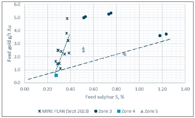
Source: Ausenco, 2023
| Courageous Lake Project | Page 135 |
| Pre-feasibility Study and Preliminary Economic Assessment NI 43-101 Technical Report | January 5, 2024 |
| Figure 13-5: | Gold and Arsenic Grades Relationship in Mineralized Material
– ALS 2023 |
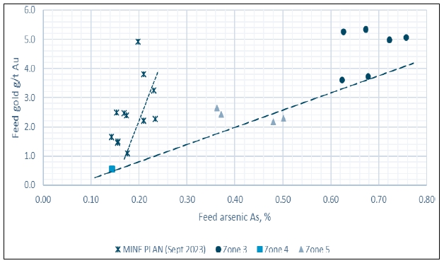
Source: Ausenco, 2023
| 13.14.1 | Recovery Modelling |
ALS 2023 and SGS 2011/2012 test results
were analyzed at the grind size of 100 μm to provide a recovery model for use with the mine production schedule to provide metals
recovery and production data. The tests included open circuit and locked cycle bulk rougher flotation and single-stage cleaner flotation
tests of the Courageous Lake master composites and variability samples to project metal recoveries into a flotation concentrate.
Correlations of the data were established
resulting in the following regression formulas and relationships:
| ● | Gold rougher tails grade: |
| o | (Au in feed 0.5 - 4.5 g/t and Au/S<6): Au rougher tails
grade = 0.053 x (g/t Au in feed) |
| o | (Au in feed 4.5 – 5.6 g/t and Au/S≥6): Au rougher
tails grade = 0.034 |
| ● | Gold cleaner concentrate recovery = -0.45 x ln(Au rougher concentrate grade)+99.3 |
| ● | Silver rougher recovery (Ag in feed = 0.25-1.5 g/t) = 89% |
| ● | Silver cleaner concentrate recovery: |
| o | (Ag rougher concentrate grade > 5.5 g/t): recovery = 96% |
| o | (Ag rougher concentrate grade < 5.5 g/t): recovery = 2.837 x (Ag rougher concentrate grade) + 80.867 |
| Courageous Lake Project | Page 136 |
| Pre-feasibility Study and Preliminary Economic Assessment NI 43-101 Technical Report | January 5, 2024 |
| ● | Sulfur rougher tails grade = 0.06x(%S in feed) |
| ● | Sulfur cleaner concentrate recovery: |
| o | (Au/S > 6): recovery = 1.65 x (%S in feed) + 96.8 |
| o | (Au/S < 6): recovery = 1.65 x (%S in feed) + 94.8 |
| ● | Arsenic rougher recovery (%As in feed = 0.1-0.8) = 97% |
| ● | Arsenic cleaner concentrate recovery = 1.2029 x As rougher recovery –
21.721 |
| ● | Iron rougher recovery = -28.3 x ln(% Fe in feed/%S in feed) + 81.155 |
| ● | Iron cleaner concentrate recovery = -7.8376 x (% Fe in feed/%S in feed) +
64.111 |
| ● | Carbon rougher recovery = 0.5705 x (%C in feed) + 0.2159 |
| ● | Carbon cleaner concentrate recovery = 0.5012 x C rougher recovery –
1.7713 |
Based on the plant feed grades and the metallurgical models
the projected LOM recoveries are 89.3% for gold, 91% for sulfur and 24% for silver.
Cleaner concentrate grades over the LOM are expected to be
in the range shown in Table 13-20 below.
| Table 13-20: | Predicted Cleaner Flotation Concentrate Grade Over Life of
Mine |
| Year |
Cleaner
Flotation Conc Grade |
| Au
(g/t) |
Ag
(g/t) |
S
(%) |
As
(%) |
Fe
( %) |
C(t),
% |
| 1 |
174.8 |
14.3 |
12.7 |
6.5 |
17.4 |
0.2 |
| 2 |
130.7 |
12.6 |
12.9 |
6.7 |
18.0 |
0.2 |
| 3 |
90.5 |
12.0 |
12.3 |
5.9 |
16.7 |
0.1 |
| 4 |
94.6 |
10.7 |
12.0 |
5.3 |
16.3 |
0.1 |
| 5 |
65.7 |
13.1 |
10.9 |
5.7 |
11.5 |
0.1 |
| 6 |
84.1 |
20.1 |
12.0 |
7.2 |
15.8 |
0.1 |
| 7 |
61.7 |
12.7 |
10.5 |
5.8 |
9.1 |
0.1 |
| 8 |
63.6 |
12.8 |
10.7 |
5.3 |
11.7 |
0.1 |
| 9 |
94.4 |
17.9 |
11.4 |
6.1 |
12.9 |
0.1 |
| 10 |
110.8 |
19.8 |
12.6 |
7.6 |
17.3 |
0.2 |
| 11 |
81.6 |
19.3 |
12.3 |
7.9 |
16.3 |
0.1 |
| 12 |
45.0 |
16.1 |
10.3 |
6.7 |
8.3 |
0.1 |
| 13 |
33.5 |
14.4 |
10.7 |
6.0 |
10.5 |
0.1 |
In addition to the predicted leach extraction of 97%, plant
losses were estimated at 0.5%. These recoveries are reflective of the testwork performed to date and were applied to the mine planning
and financial modelling.
| Courageous Lake Project | Page 137 |
| Pre-feasibility Study and Preliminary Economic Assessment NI 43-101 Technical Report | January 5, 2024 |
Figure 13-6 shows the predicted and actual test work recovery
performance.
| Figure 13-6: | Predicted and Test work Gold Recoveries vs. Feed Grade –
ALS 2023 |
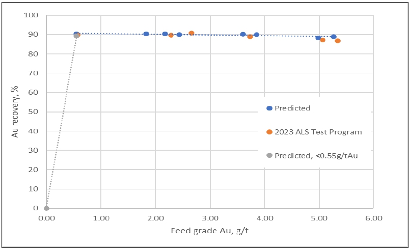
Source: Ausenco, 2023
| 13.15 | Deleterious Elements |
The deleterious element assay for eight
variability samples from ALS 2023 test program indicate all samples contained less than one ppm of mercury, which was the laboratory’s
detection point. It does not appear that mercury would become a deleterious element that could have a significant economic effect on potential
extraction in the final doré; however, further analysis may be required to confirm the precise mercury concentration at lower detection
point.
| 13.16 | Walsh Lake Deposit – SGS 2013 |
The current flowsheet design is based
on metallurgical testing completed on Courageous Lake deposit; however, in 2013, SGS Lakefield performed test work on Walsh Lake deposit
located near Courageous Lake deposit under the request of Seabridge Gold. The metallurgical performance of the samples from Walsh Lake
deposit are not considered for the development of the process flowsheet described in Section 17.
| Courageous Lake Project | Page 138 |
| Pre-feasibility Study and Preliminary Economic Assessment NI 43-101 Technical Report | January 5, 2024 |
| 13.16.1 | Head Assay – Walsh Lake Deposit |
A head assay for three zone composite
samples from Walsh Lake deposit was determined for gold, silver, sulfur, arsenic, carbon, iron, calcium and other major, minor, and trace
elements. All the drill cores crushed to 100% passing 10 mesh. The gold head analysis determined by a screened metallic protocol showed
2.80 g/t for Zone 1, 12.2 g/t for Zone 2, and 2.95 g/t for Zone 3 composite. The head assay results of the samples are given in Table
13-21.
| Table 13-21: | Walsh Lake Head Assay |
| Head
Analysis |
Composite
Zone 1 |
Composite
Zone 2 |
Composite
Zone 3 |
| Au g/t |
2.80 |
12.20 |
2.95 |
| Ag g/t |
<2 |
<2 |
<2 |
| As % |
0.70 |
4.10 |
0.43 |
| Ca g/t |
24400.00 |
29100.00 |
32000.00 |
| Cu g/t |
85.60 |
65.00 |
81.70 |
| C(t) % |
0.11 |
0.16 |
0.28 |
| CO3 % |
<0.05 |
<0.05 |
0.70 |
| Fe % |
10.10 |
11.50 |
8.06 |
| S % |
0.94 |
2.84 |
1.94 |
| S-
% |
0.92 |
2.76 |
1.97 |
| TOC % |
0.12 |
0.14 |
0.12 |
| 13.16.2 | Direct Cyanidation – Walsh Lake Deposit |
A series of five bottle roll cyanidation
tests were conducted on composite samples from all three zones to evaluate the amenability of the mineralized material to cyanide leaching.
The results are presented in Table 13-22. The highest gold extraction is 96.1% for CN 2 (Zone 1). The lowest gold extraction is 92.9%
for CN1 (Zone 2), but another test on Zone 2 (CN5) shows a 95% extraction. The cyanidation test results show that samples are amenable
to leaching by standard, direct cyanidation procedures. The direct cyanidation results does not show any indication of Walsh Lake material
being refractory.
| Table 13-22: | Summary of Cyanidation Testwork |
| |
|
Feed
Size |
Reagent
Consumption |
Extraction
(%) |
Residue
Assay
(g/t) |
Head
Calc.
(g/t) |
Head
Direct (g/t) |
| Composite |
Test
No. |
(kg/t) |
| |
|
|
NaCN |
CaO |
Au |
Ag |
Au |
Ag |
Au |
Ag |
Au |
| Zone 2 |
CN1 |
86 |
1.76 |
0.39 |
92.90 |
>39.60 |
0.82 |
<2.00 |
11.60 |
- |
12.20 |
| Zone 1 |
CN2 |
64 |
0.15 |
0.58 |
96.10 |
>41.00 |
0.12 |
<0.50 |
2.98 |
0.85 |
2.80 |
| Zone 2 |
CN3 |
82 |
0.17 |
0.80 |
93.10 |
>70.00 |
0.84 |
<0.50 |
12.20 |
1.67 |
12.20 |
| Zone 3 |
CN4 |
62 |
0.16 |
0.63 |
93.80 |
60.20 |
0.18 |
<0.50 |
2.89 |
1.26 |
2.95 |
| Courageous Lake Project | Page 139 |
| Pre-feasibility Study and Preliminary Economic Assessment NI 43-101 Technical Report | January 5, 2024 |
| |
|
Feed
Size (µm) |
Reagent
Consumption |
Extraction
(%) |
Residue
Assay
(g/t) |
Head
Calc.
(g/t) |
Head
Direct (g/t) |
| Composite |
Test
No. |
(kg/t) |
| |
|
NaCN |
CaO |
Au |
Ag |
Au |
Ag |
Au |
Ag |
Au |
| Zone 2 |
CN5 |
62 |
0.65 |
1.29 |
95.00 |
85.60 |
0.61 |
0.20 |
12.10 |
1.39 |
12.20 |
| 13.16.3 | Flotation – Walsh Lake Deposit |
A series of flotation tests
were undertaken using all three composites. The 2013 test work employed standard sulfide flotation reagents including 80 g/t of PAX,
10 g/t of A208, 10 g/t of MIBC, and 50 g/t of CuSO4 added to activate the sulfides. The rougher flotation test results are
shown in Table 13-23.
| Table 13-23: | Rougher Flotation Test Results – Walsh Lake Deposit |
| Sample |
Head
Assay |
Primary
Grind |
Rougher
Mass
Pull |
Rougher
Concentrate Distribution (%) |
Rougher
Concentrate Grade |
| ID |
(g/t) |
Size
(µm) |
(%) |
Au
|
S
|
Fe
|
As
|
Ct
|
Ag
|
Au |
S |
Fe |
As |
Ct |
Ag |
| (g/t) |
% |
(%) |
(%) |
(%) |
g/t |
| Zone 1 |
126 |
126 |
15.4 |
91.9 |
90.2 |
26.5 |
97.0 |
22.7 |
16.2 |
17.3 |
6.5 |
18.4 |
4.8 |
0.2 |
<10.0 |
| Zone 2 |
104 |
104 |
22.9 |
95.1 |
95.3 |
43.8 |
96.8 |
23.1 |
22.9 |
48.0 |
10.9 |
23.4 |
16.5 |
0.2 |
<10.0 |
| Zone 3 |
90 |
90 |
14.5 |
87.8 |
86.0 |
36.8 |
94.8 |
19.0 |
14.6 |
18.6 |
11.6 |
21.7 |
2.7 |
0.3 |
<10.0 |
Rougher flotation tests show gold recoveries
ranging from 87.8% on high grade material to 95.1% on lower grade material. The concentrates mass pulls ranges from 14.5% to 22.9% of
the original composite weight.
The QP has performed various checks
to verify that the data that were used to estimate resources that are the subject of this report. Based on these checks, it is the QP’s
opinion that the data are suitable to be used to estimate Mineral Resources.
| Courageous Lake Project | Page 140 |
| Pre-feasibility Study and Preliminary Economic Assessment NI 43-101 Technical Report | January 5, 2024 |
| 14 | MINERAL RESOURCE ESTIMATES |
The Mineral Resource for the Project
has been updated with revised estimates by Sue Bird, P. Eng. (APEGBC #25007) of Moose Mountain Technical Services (MMTS) in accordance
with the updated Canadian Institute of Mining, Metallurgy and Petroleum (CIM) Definition Standards (CIM 2014) and have been estimated
using the 2019 CIM Best Practices Guidelines. The resource modelling now includes both Courageous Lake and Walsh lake within the Project,
and includes additional drilling by Seabridge on Courageous Lake in 2018 as well as an updated modelling methodology.
| 14.2 | Mineral Resource Estimate |
The Resource Estimate for the Project deposits is summarized
in the following tables.
Table 14-1 summarizes the 2024 Courageous
Lake deposit mineral Resource Estimate (MRE) at various cut-offs with the base case cut-off highlighted. The base case cut-off is 0.80
g/t Au and covers the Processing and G&A costs. Table 14-2 summarizes the Walsh Lake total MRE with Table 14-3 summarizing the processing
recoveries used for both Courageous and Walsh Lake, based on the Au grade. Mineral resources that are not mineral reserves do not have
demonstrated economic viability.
The effective date of the Courageous Lake and Walsh Lake
Resource Estimates is January 5, 2024.
| Table 14-1: | 2024 Mineral Resource Estimate for the Courageous Lake
Deposit |
| Class |
Au
Cutoff (g/t) |
Tonnage
(ktonnes) |
Au
Grade (g/t) |
Au
Metal (koz) |
|
Measured |
0.5 |
6,976 |
2.532 |
568 |
| 0.6 |
6,624 |
2.638 |
562 |
| 0.7 |
6,341 |
2.726 |
556 |
| 0.8 |
6,007 |
2.836 |
548 |
| 0.9 |
5,695 |
2.945 |
539 |
| 1.0 |
5,424 |
3.045 |
531 |
| 1.5 |
4,147 |
3.601 |
480 |
| 2.0 |
3,231 |
4.129 |
429 |
| 3.0 |
1,847 |
5.382 |
320 |
|
Indicated |
0.5 |
171,442 |
2.017 |
11,120 |
| 0.6 |
160,352 |
2.119 |
10,924 |
| 0.7 |
149,422 |
2.226 |
10,696 |
| 0.8 |
139,167 |
2.335 |
10,449 |
| 0.9 |
129,234 |
2.450 |
10,178 |
| Courageous Lake Project | Page 141 |
| Pre-feasibility Study and Preliminary Economic Assessment NI 43-101 Technical Report | January 5, 2024 |
| Class |
Au
Cutoff (g/t) |
Tonnage
(ktonnes) |
Au
Grade (g/t) |
Au
Metal (koz) |
| |
1.0 |
120,140 |
2.563 |
9,901 |
| 1.5 |
84,347 |
3.126 |
8,478 |
| 2.0 |
58,963 |
3.726 |
7,063 |
| 3.0 |
29,606 |
5.004 |
4,763 |
|
Measured + Indicated |
0.5 |
178,418 |
2.038 |
11,688 |
| 0.6 |
166,976 |
2.139 |
11,486 |
| 0.7 |
155,763 |
2.247 |
11,251 |
| 0.8 |
145,174 |
2.356 |
10,997 |
| 0.9 |
134,929 |
2.470 |
10,717 |
| 1.0 |
125,564 |
2.584 |
10,432 |
| 1.5 |
88,494 |
3.149 |
8,958 |
| 2.0 |
62,194 |
3.747 |
7,492 |
| 3.0 |
31,453 |
5.026 |
5,083 |
|
Inferred |
0.5 |
52,701 |
2.086 |
3,534 |
| 0.6 |
47,836 |
2.242 |
3,448 |
| 0.7 |
43,998 |
2.381 |
3,368 |
| 0.8 |
40,603 |
2.517 |
3,286 |
| 0.9 |
37,280 |
2.666 |
3,196 |
| 1.0 |
34,638 |
2.797 |
3,115 |
| 1.5 |
23,885 |
3.499 |
2,687 |
| 2.0 |
16,494 |
4.286 |
2,273 |
| 3.0 |
8,104 |
6.208 |
1,617 |
Note:
| 1. | The Mineral Resource estimates have been done by Sue Bird, P.Eng., the independent QP and are reported
using the 2014 CIM Definition Standards and were estimated using the 2019 CIM Best Practices Guidelines, as required by NI43-101 |
| 2. | The base case Mineral Resource has been confined by “reasonable prospects of eventual economic extraction”
shape using the following assumptions: Metal prices is US$1,400/oz Gold; Metallurgical recovery variable with Grade as summarized in Table
14-3; Offsite Costs (transport, smelter treatment and refining) are US$3.50/oz Au; Processing costs are US$24.21/tonne milled, General
and Administrative (“G&A”) costs of US$14.08/ tonne milled; Mining cost of US$2.87/ tonne; and 50 degree pit slopes with
the 150% price case pit shell used for the confining shape |
| 3. | The resulting NSR = Au*US$44.90/g * Recovery% |
| 4. | The specific gravity is 2.72 except for the diabase dykes which have an sg of 2.85 and the overburden
with an sg of 2.0 |
| 5. | Numbers may not add due to rounding |
| Courageous Lake Project | Page 142 |
| Pre-feasibility Study and Preliminary Economic Assessment NI 43-101 Technical Report | January 5, 2024 |
| Table 14-2: | 2024
Resource Statement for the Walsh Lake Deposit |
| Classification |
Au
Cut-off (g/t) |
Tonnes
(ktonnes) |
Au
Grade (g/t) |
Au
Metal (koz) |
|
Inferred |
0.5 |
5,081 |
3.514 |
574.1 |
| 0.6 |
4,692 |
3.760 |
567.1 |
| 0.7 |
4,366 |
3.992 |
560.4 |
| 0.8 |
4,134 |
4.175 |
554.8 |
| 0.9 |
3,910 |
4.364 |
548.6 |
| 1.0 |
3,662 |
4.596 |
541.1 |
| 1.5 |
2,909 |
5.468 |
511.4 |
| 2.0 |
2,357 |
6.341 |
480.5 |
| 3.0 |
1,668 |
7.935 |
425.5 |
Note:
| 1. | The Mineral Resource estimates have been done by Sue Bird, P.Eng., the independent QP and are reported
using the 2014 CIM Definition Standards and were estimated using the 2019 CIM Best Practices Guidelines, as required by NI43-101 |
| 2. | The base case Mineral Resource has been confined by “reasonable prospects of eventual economic extraction”
shape using the following assumptions: Metal prices is US$1400/oz Gold; Metallurgical recovery variable with Grade as summarized in Table
14-3; Offsite Costs (transport, smelter treatment and refining) are US$3.50/oz Au; Processing costs are US$24.21/tonne milled, General
and Administrative (“G&A”) costs of US$14.08/ tonne milled; Mining cost of US$2.87/ tonne; and 50 degree pit slopes with
the 150% price case pit shell used for the confining shape |
| 3. | The resulting NSR = Au*US$44.90/g * Recovery% |
| 4. | The specific gravity is 2.90 in the metavolcanics and 2.84 in the metasediments |
| 5. | Numbers may not add due to rounding |
| Table 14-3: | Metallurgical Recoveries Used for the Project |
| Au
Grade Range (g/t) |
Recovery
(%) |
| <0.3 |
0 |
| 0.3-0.5 |
40 |
| 0.5-0.75 |
65 |
| 0.75-3.0 |
=
-0.1423 x AU 5 + 0.2604 x AU 4 + 5.593 x AU 3 - 30.217 x AU 2 + 60.566 x AU + 44.935 |
| 3.0-5.0 |
93 |
| 5.0-8.0 |
94 |
| >8.0 |
96 |
The QP for the
Resource Estimate is not aware of any environmental, permitting, legal, title, taxation, socio-economic, marketing, political, or
other relevant factors that could materially affect the mineral Resource Estimate. Factors that may affect the estimates include:
metal price assumptions, changes in interpretations of mineralization geometry and continuity of mineralization zones, changes to
kriging assumptions, metallurgical recovery assumptions, operating cost assumptions, confidence in the modifying factors, including
assumptions that surface rights to allow mining infrastructure to be constructed will be forthcoming, delays or other issues in
reaching agreements with local or regulatory authorities and stakeholders, and changes in land tenure requirements or in permitting
requirement.
| Courageous Lake Project | Page 143 |
| Pre-feasibility Study and Preliminary Economic Assessment NI 43-101 Technical Report | January 5, 2024 |
| 14.3 | Key Assumptions and Data Used in the Resource Estimate |
A summary of the total number of drill
holes used for the Resource Estimates is found in Table 14-4 and Table 14-5. Un-assayed values in the courageous lake database have been
treated as missing as it is noted that Noranda was drilling for underground targets and did not assay outside of the underground high-grade
area. It must be noted that over 97% of the Seabridge drilling within the main mineralized domains (domains 2-6 and 8) has been assayed.
Un-assayed intervals are primarily within the remaining, lower grade domains. All zero value assays and missing assays values for Walsh
Lake have been treated as zero and are not within mineralized zones.
| Table 14-4: | Summary of Drill holes and Assays used in the Courageous
Lake Resource Estimate |
Company |
Number
of
DHs |
Total
Depth
(m) |
Length
Assayed
(m) |
Total
% Assayed
(m) |
Total
length Within
Modelled
Mineralized
Zones (m) |
%
Assayed within Zones |
| Placer Dome |
315 |
83,285.9 |
41,230.4 |
50% |
34,727.8 |
98% |
| Noranda |
96 |
22,684.2 |
22,109.7 |
97% |
16,064.1 |
100% |
| Seabridge |
199 |
69,285.6 |
63,828.5 |
92% |
39,772.7 |
100% |
| Unknown |
6 |
711.3 |
- |
- |
- |
- |
| Total |
616 |
175,967.0 |
127,168.6 |
72% |
90,564.7 |
99% |
Note: values may not sum due to rounding
| Table 14-5: | Summary of Drill holes and Assays used in the Walsh
Lake Resource Estimate |
Year |
Number
of Drill holes |
Total
Depth
(m) |
Length
Assayed (m) |
Total
% Assayed (m) |
Total
length Within
Modelled Mineralized
Zones
(m) |
%
Assayed within Zones |
| 1987 |
24 |
3,996.9 |
693.6 |
17% |
0.0 |
100% |
| 1988 |
3 |
1,884.0 |
373.4 |
20% |
0.0 |
100% |
| 1989 |
6 |
2,307.9 |
154.97 |
7% |
0.0 |
100% |
| 2006 |
1 |
284.7 |
275.5 |
97% |
6.0 |
100% |
| 2010 |
1 |
522.0 |
241.5 |
46% |
6.0 |
100% |
| 2011 |
6 |
1,554.0 |
14.1 |
1% |
0.0 |
100% |
| 2012 |
22 |
8,365.0 |
7,877.8 |
94% |
325.0 |
100% |
| 2013 |
29 |
8,278.0 |
7,902.8 |
95% |
294.0 |
100% |
| Total |
92 |
27,192.4 |
17,533.7 |
64% |
631.0 |
100% |
| Courageous Lake Project | Page 144 |
| Pre-feasibility Study and Preliminary Economic Assessment NI 43-101 Technical Report | January 5, 2024 |
| 14.3.2 | Topography and Previous Mining |
Topography has been provided as contour
lines and surfaces by Seabridge. There has been no previous mining at either deposit.
| 14.4 | Mineralization Models |
Confining shapes for the interpolations
have been supplied by Seabridge for Courageous Lake and reviewed by the QP. At Courageous Lake there are thirteen domains modelled, as
well as a dyke shape, and overburden. The main mineralized shapes are illustrated in Figure 14-1.
At Walsh Lake there has been mineralized
tagging done on the assays, based on preliminary mineralized shapes. The assay tagging and resulting shape created by indicator interpolation
of the tags are illustrated in Figure 14-2.
| Figure 14-1: | Three-dimension View of Modelling Shapes - Courageous Lake |
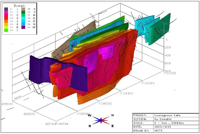
Source: MMTS, 2023
| Courageous Lake Project | Page 145 |
| Pre-feasibility Study and Preliminary Economic Assessment NI 43-101 Technical Report | January 5, 2024 |
| Figure 14-2: | Three-dimension View of Mineralized Tagging –
Walsh Lake |
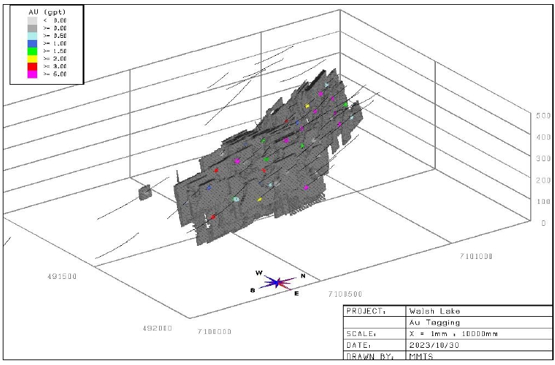
Source: MMTS, 2023
| 14.5 | Assay Statistics, and Compositing |
MMTS has examined the sample assays
in the veins using boxplots, histograms, and cumulative probability plots (CPPs).
| 14.5.1 | Cumulative Probability Plots (CPPs) |
The grade distribution is shown in the
following figures as CPPs for Au in each by domain. The grade distributions are mainly lognormal except at very high grades where outliers
are evident and therefore outlier restriction of high grades has been done.
The Courageous Lake CPP by domains are
illustrated in Figure 14-3 and Figure 14-4. The CPP within the modelled area and within the tagged assays is illustrated in Figure 14-5
for Walsh Lake.
| Courageous Lake Project | Page 146 |
| Pre-feasibility Study and Preliminary Economic Assessment NI 43-101 Technical Report | January 5, 2024 |
| Figure 14-3: | CPP of Au by
Domain – Courageous Lake Domains 2-6 |
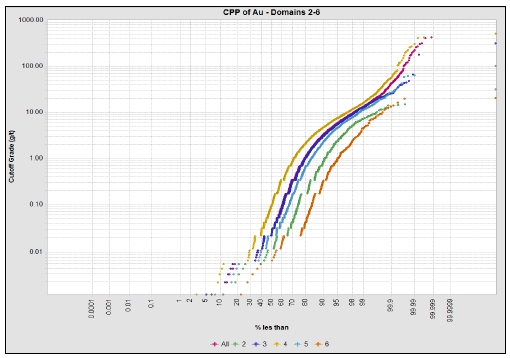
Source: MMTS, 2023
| Figure 14-4: | CPP of Au by Domain – Courageous Lake Domains 1, 7-14 |
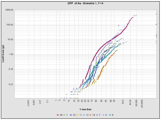
Source: MMTS, 2023
| Courageous Lake Project | Page 147 |
| Pre-feasibility Study and Preliminary Economic Assessment NI 43-101 Technical Report | January 5, 2024 |
| Figure 14-5: | CPP of Au by Domain – Walsh Lake |
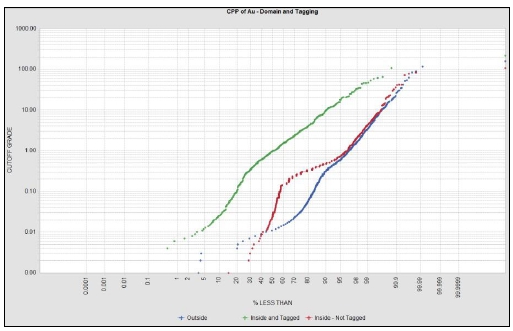
Source: MMTS, 2023
| 14.5.2 | Outlier Restrictions |
Table 14-6 summarizes the outlier restrictions
applied to the composites during interpolation at Courageous Lake. For composite grades above the outlier value provided, and at distances
greater than 5 m from the data, the value is essentially capped to the outlier. Table 14-7 summarizes the capping values applied to the
assay data at Walsh Lake.
| Table 14-6: | Outlier Restriction of Composites by Domain – Courageous
Lake |
| Domain |
Outlier
Value (g/t) |
| 1 |
15 |
| 2 |
15 |
| 3 |
20 |
| 4 |
50 |
| 5 |
20 |
| 6 |
20 |
| 7 |
15 |
| 8 |
10 |
| 9 |
8 |
| 10 |
50 |
| 11 |
10 |
| 12 |
10 |
| 14 |
5 |
| Courageous Lake Project | Page 148 |
| Pre-feasibility Study and Preliminary Economic Assessment NI 43-101 Technical Report | January 5, 2024 |
| Table 14-7: | Capping of Assays – Walsh Lake |
| Source |
Au
Cap Value (g/t) |
| Outside Deposit Domain |
10 |
| Inside Deposit Domain – Not Tagged as Mineralized |
50 |
| Inside Deposit Domain – Tagged as Mineralized |
80 |
Histograms of the assay intervals for
the Courageous Lake and Walsh Lake deposits are shown in Figure 14-6 and Figure 14-7.
At Courageous Lake 5 m composites were
used, while at Walsh lake 3 m compositing was done. This is longer than virtually all of the assay length and corresponds to the block
height used at each deposit. The compositing honored the domain boundaries at Courageous Lake with assay intervals less than half the
total length (2.5 m at Courageous Lake and 1.5 m at Walsh Lake) added to the previous composite to limit the number of small assay intervals.
| Figure 14-6: | Histograms of Assay Lengths within Mineralized Domains
– Courageous Lake |
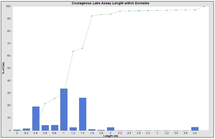
Source: MMTS, 2023
| Courageous Lake Project | Page 149 |
| Pre-feasibility Study and Preliminary Economic Assessment NI 43-101 Technical Report | January 5, 2024 |
| Figure 14-7: | Histograms of Assay Lengths within Mineralization -
Walsh Lake |
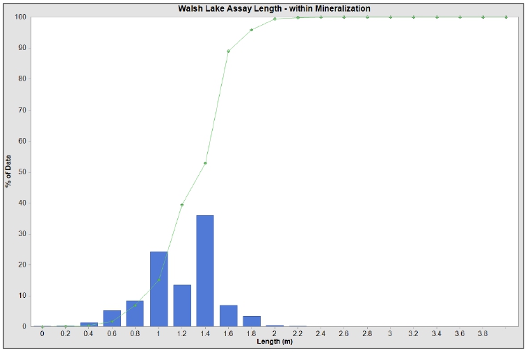
Source: MMTS, 2023
| 14.5.4 | Assay and Composite Statistics |
The assay and composite basic statistics
within the modelled domains are summarized in the following tables. The capped composite coefficients of variation (CV) is generally less
than 3.0, and this is without the outlier restrictions applied, demonstrating that linear interpolations are appropriate.
| Courageous Lake Project | Page 150 |
| Pre-feasibility Study and Preliminary Economic Assessment NI 43-101 Technical Report | January 5, 2024 |
| Table 14-8: | Assays and Composites Statistics within the Domains, Courageous
Lake - Au |
| |
Domain |
| Source |
Parameter |
|
|
|
|
|
|
|
|
|
|
|
|
|
| |
|
1 |
2 |
3 |
4 |
5 |
6 |
7 |
8 |
9 |
10 |
11 |
12 |
14 |
|
Assays |
# Samples |
864 |
4,634 |
19,151 |
34,463 |
12,277 |
4,446 |
1,256 |
1,997 |
2,580 |
277 |
144 |
125 |
1,185 |
| # Missing |
78 |
323 |
899 |
999 |
614 |
184 |
39 |
89 |
86 |
5 |
4 |
0 |
50 |
| Min (g/t) |
0.001 |
0.001 |
0.001 |
0.001 |
0.001 |
0.001 |
0.001 |
0.001 |
0.001 |
0.001 |
0.001 |
0.001 |
0.001 |
| Max (g/t) |
16.790 |
31.880 |
313.550 |
516.340 |
101.200 |
20.520 |
19.540 |
111.470 |
19.870 |
105.490 |
13.660 |
21.870 |
93.880 |
| Wtd mean (g/t) |
0.232 |
0.310 |
0.832 |
1.291 |
0.668 |
0.149 |
0.200 |
0.937 |
0.161 |
0.850 |
0.240 |
0.363 |
0.173 |
| Wtd CV |
4.0 |
3.8 |
3.6 |
4.3 |
3.5 |
5.7 |
4.8 |
5.4 |
4.0 |
9.0 |
5.7 |
5.2 |
16.6 |
|
Composites |
# Samples |
239 |
1,238 |
4,504 |
7,476 |
3,063 |
1,247 |
345 |
457 |
734 |
77 |
40 |
31 |
348 |
| # Missing |
213 |
632 |
1,072 |
886 |
1,015 |
304 |
185 |
102 |
220 |
8 |
0 |
0 |
125 |
| Min (g/t) |
0.001 |
0.001 |
0.001 |
0.001 |
0.001 |
0.001 |
0.001 |
0.001 |
0.001 |
0.001 |
0.0013 |
0.0011 |
0.001 |
| Max (g/t) |
6.290 |
9.182 |
52.692 |
147.738 |
23.552 |
7.492 |
5.666 |
37.292 |
7.042 |
31.935 |
4.925 |
3.601 |
20.144 |
| Wtd mean (g/t) |
0.232 |
0.310 |
0.832 |
1.291 |
0.668 |
0.149 |
0.200 |
0.937 |
0.161 |
0.850 |
0.240 |
0.363 |
0.173 |
| Wtd CV |
2.8 |
2.7 |
2.2 |
2.6 |
2.3 |
3.6 |
3.1 |
3.5 |
2.7 |
4.6 |
3.5 |
2.4 |
7.8 |
| Difference in Wt. Mean (%) |
0% |
0% |
0% |
0% |
0% |
0% |
0% |
0% |
0% |
0% |
0% |
0% |
0% |
| Courageous Lake Project | Page 151 |
| Pre-feasibility Study and Preliminary Economic Assessment NI 43-101 Technical Report | January 5, 2024 |
| Table 14-9: | Assays and Composites Statistics within the Mineralized Domain,
Walsh Lake – Au |
| |
|
Source |
| Source |
Parameter |
Uncapped |
Capped |
| |
|
Outside
Doman |
Inside
Domain |
Inside
Domain and
mineralized
zone |
Outside
Doman |
Inside
Domain |
Inside
Domain and
mineralized
zone |
|
Assays |
# Samples |
6,278 |
13,399 |
638 |
6,278 |
13,399 |
638 |
| # Missing |
0 |
0 |
0 |
0 |
0 |
0 |
| Min (g/t) |
0 |
0 |
0.003 |
0 |
0 |
0.003 |
| Max (g/t) |
108.500 |
215.010 |
215.010 |
10.000 |
80.000 |
80.000 |
| Wtd mean (g/t) |
0.117 |
0.251 |
3.868 |
0.096 |
0.234 |
3.590 |
| Wtd CV |
11.3 |
11.3 |
3.2 |
5.1 |
8.7 |
2.4 |
|
Composites |
# Samples |
4,303 |
7,472 |
279 |
4,303 |
7,472 |
279 |
| # Missing |
0 |
0 |
0 |
0 |
0 |
0 |
| Min (g/t) |
0 |
0 |
0.007 |
0 |
0 |
0.007 |
| Max (g/t) |
24.346 |
93.619 |
93.619 |
7.883 |
35.115 |
35.115 |
| Wtd mean (g/t) |
0.118 |
0.251 |
3.868 |
0.096 |
0.234 |
3.590 |
| Wtd CV |
11.3 |
11.3 |
3.2 |
5.1 |
8.7 |
2.4 |
| Difference in Wt. Mean (%) |
0% |
0% |
0% |
0% |
0% |
0% |
At Courageous Lake variograms have been
made by combining domains 3 through 5 and using the indicators. Variography has been used as a guide for the search distances a well as
the classification to measured and indicated. Results for the down-dip and horizontal directions of the Au indicator are illustrated in
Figure 14-8.
| Courageous Lake Project | Page 152 |
| Pre-feasibility Study and Preliminary Economic Assessment NI 43-101 Technical Report | January 5, 2024 |
| Figure 14-8: | Variogram Model for Au Indicator at Courageous Lake,
Major and Minor Axis |
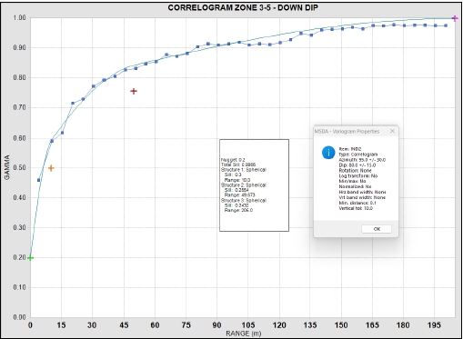
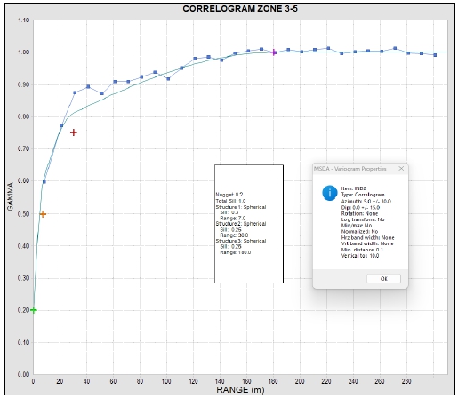
Source: MMTS, 2023
| Courageous Lake Project | Page 153 |
| Pre-feasibility Study and Preliminary Economic Assessment NI 43-101 Technical Report | January 5, 2024 |
The specific gravity (SG) at Courageous
Lake is based on 471 measurements. The SG is 2.72 except for the diabase dykes which have an SG of 2.85 and the overburden with an SG
of 2.0.
The specific gravity at Walsh Lake is
based on 1,541 measurements within the deposit area and has been assigned based on the lithology. The SG is 2.90 in the metavolcanics
and 2.84 in the metasediments.
Block dimensions are 5 x 5 x 5 m with the extent of the block
models summarized in UTM coordinates, in Table 14-10.
| Table 14-10: | Courageous Lake and Walsh Lake Model Extents |
| Deposit |
Direction |
Minimum |
Maximum |
Extent |
Block
size |
#
Blocks |
|
Courageous Lake |
Easting |
485700 |
487800 |
2100 |
5 |
420 |
| Northing |
7108200 |
7111600 |
3400 |
5 |
680 |
| Elevation |
-1045 |
455 |
1500 |
5 |
300 |
|
Walsh Lake |
Easting |
491150 |
491900 |
750 |
3 |
250 |
| Northing |
7100060 |
7101200 |
1140 |
3 |
380 |
| Elevation |
0 |
480 |
480 |
3 |
160 |
| 14.8.1 | Interpolation Parameters - Courageous Lake |
A very similar methodology previously
used for Au grade estimation as outlined in TetraTech (2013) has been employed for the current Resource Estimate of Courageous Lake. The
following has been taken from this report and is provided here for completeness with minor edits.
| 14.8.2 | Domains 2 through 6 and Domain 8 Modelling |
Domains 2 through 6 and 8 contain 99% of the currently defined
Courageous Lake mineral resources.
To provide additional constraints in
estimating block grades in these domains, and to minimize grade smearing and dilution, two distinct methods were employed:
The first method helps to define zones
of high probability of mineralization within the more broadly defined zone wireframes. The second method of constraint helped to define
the mineralization as lenses and shoots that tend to be sub-parallel to stratigraphic/zone contacts by being more selective as to which
drill hole composites were used to estimate block grades.
| Courageous Lake Project | Page 154 |
| Pre-feasibility Study and Preliminary Economic Assessment NI 43-101 Technical Report | January 5, 2024 |
The mineral zones contain a significant
amount of low-grade assays. Gold indicator models were constructed at 0.1, 0.2, and 0.3 g/t cut-off grades by assigning 0’s and 1’s to
drill hole composites below and above the indicator cut-off, respectively. A three-pass inverse distance squared estimator was used to
interpolate block gold indicator probabilities using these ‘binary’ values. The three indicator probability passes used search
ellipses of 20 m, 60 m and 120 m, and required a minimum of three composites, a maximum of 8 composites, with no more than two composites
per drill hole. The 0.2 g/t indicator has been selected to determine the presence of mineralization with reasonable continuity within
the zone wireframes using a 50% probability threshold. This segregated the blocks inside of mineral zones 2 through 6 and 8 into unmineralized
(AUZON = 2) and mineralized populations (AUZON = 1).
The second method for constraining the
estimate of block gold grades was centered on selecting eligible composites based on the relative distance between each model block and
the mineral zone hanging wall and footwall contacts (for zones 2 through 6 and 8 only). The Cartesian distance between block centroid
locations and the zone contacts were calculated and stored in the blocks. The relative distance between the two surfaces for each block
was calculated using the following expression:

For example, a relative distance (RELZ)
of 100 means that the block is located at the hanging wall contact while a RELZ distance of zero means the block is located near the footwall
contact. The 5 m long drill hole composites were backtagged with the block RELZ value. This ensured that the position of both the blocks
and the drill holes relative to the zone contacts was established.
Block gold grades for mineral zones
2 through 6 and 8 were then estimated using a three-pass inverse distance cubed estimator. Block/composite ZONE and AUZON matching was
used, meaning that a block located in Zone 4 and inside of AUZON 1 could only be estimated by composites from those two populations. The
“relative elevation” option was selected in MineSight® for the three inverse distance runs that featured increasing longer
search ellipse dimensions. An option was set with a value of 10, which allowed for more samples to be used in the block estimates.
For a block with a RELZ value of 15
(block is located near the footwall contact), eligible composites could have RELZ values ranging between 5 and 25 (i.e. ±10 units).
The PAR20 value is like a ‘rheostat’ that lets the user smooth or sharpen the estimate of block grades by allowing fewer or
more composites perpendicular to strike to be used. De-cluster weights were assigned to the composites using the cell method (5 m x5 m
x 5 m) and multiplied by the length of the composite. The inverse distance calculation was weighted by the combined de-cluster/length
weights. This was done primarily to account for the clustered data that stems from the Noranda underground diamond drill hole fans. Table
14-11 summarizes the basic parameters that were used to estimate block gold grades for mineral zones 2 through 6 and 8.
| Courageous Lake Project | Page 155 |
| Pre-feasibility Study and Preliminary Economic Assessment NI 43-101 Technical Report | January 5, 2024 |
| Table 14-11: | Courageous
Lake Domains 2 to 6 and 8 - Au Interpolation Parameters |
| |
Number
of Composites |
|
Search
Range (m) |
|
| |
Min |
Max |
Max/Hole |
Major |
Minor |
Vert
1 |
| 1 |
3 |
8 |
2 |
30 |
30 |
30 |
| 2 |
3 |
8 |
2 |
60 |
60 |
60 |
| 3 |
1 |
8 |
1 |
120 |
120 |
120 |
Note:
| 1. | The effective “vertical” axis search was controlled by the dynamic anisotropy method, which is significantly narrower
perpendicular to the strike/dip vectors. |
Block gold grades were estimated by
a two-pass inverse distance cubed estimation process for the remaining mineral zones (1, 7, 9 to 12, and 14). The dynamic anisotropy search
strategy was not used for these zones. Inverse distance cubed estimation parameters for mineral zones 1, 7, 9, 12, 14, and 99 are summarized
in Table 14-12.
| 14.8.2.1 | Remaining Domain Modelling |
Block gold grades were estimated by
a two-pass inverse distance cubed estimation process for the remaining mineral zones (1, 7, 9 to 12, and 14). The dynamic anisotropy search
strategy was not used for these zones. Inverse distance cubed estimation parameters for mineral zones 1, 7, 9, 12, and 14 are summarized
in Table 14-12.
Estimation parameters for Domains 10
and 11 are summarized in Table 14-12.
| Table 14-12: | Courageous Lake Domains 1, 7, 9, 12, 14, 10 and 11
- Inverse Distance Parameters |
| |
Interpolation |
Number
of Composites |
Search
Range (m) |
Ellipse
Orientation (°) |
| Domains |
Run |
|
|
Max/
hole |
|
|
|
|
North
Dip |
East
Dip |
| |
Min |
Max |
Major |
Minor |
Vert |
North |
| 1, 7, 9, 12, 14 |
1 |
1 |
3 |
1 |
37.5 |
37.5 |
5 |
185 |
0 |
-85 |
| 2 |
1 |
3 |
1 |
75 |
75 |
10 |
185 |
0 |
-85 |
| 10, 11 |
1 |
1 |
3 |
1 |
37.5 |
37.5 |
5 |
170 |
0 |
-85 |
| 2 |
1 |
3 |
1 |
75 |
75 |
10 |
170 |
0 |
-85 |
Note: values may not sum due to rounding
As a step to further minimize the impact
of high-grade outlier composite grades above the “outlier restriction” values as summarized in Table 14 5 were only allowed
to be used for up to 5 m from the composite. At distances beyond 5 m they are effectively capped at the outlier value.
| 14.8.3 | Interpolation Parameters - Walsh Lake |
As at Courageous Lake, the mineral zones
contain a significant number of low-grade assays. Gold indicator models were constructed at 0.25, 0.50, 0.75, 1.0 and 2.0 g/t cut-off
grades by assigning 0’s and 1’s to drill hole composites below and above the indicator cut-off, respectively. These were used to inform
tagging of a mineralized intervals (i.e. item MIN=1). A two-pass inverse distance
squared estimator was used to interpolate block gold indicator probabilities using the binary MIN value. The indicator probability passes
used search ellipses of 30 m, and 100 m, and required a minimum of three composites, a maximum of 12 composites, with no more than 2 composites
per drill hole. A min Indicator value with a 15% probability of mineralization in the block has been used to determine flag the block
for interpolation.
| Courageous Lake Project | Page 156 |
| Pre-feasibility Study and Preliminary Economic Assessment NI 43-101 Technical Report | January 5, 2024 |
Table 14-13 summarizes the basic parameters
used to estimate block gold grades for blocks flagged as possibly mineralized.
| Table 14-13: | Walsh Lake Domains - Au Interpolation Parameters |
| Interpolation |
Number
of Composites |
Search
Range (m) |
| Run |
Min |
Max |
Max/Hole |
Major |
Minor |
Vert
1 |
| 1 |
2 |
3 |
1 |
25 |
25 |
2.5 |
| 2 |
2 |
3 |
1 |
50 |
50 |
2.5 |
| 3 |
2 |
3 |
1 |
75 |
75 |
2.5 |
| 4 |
1 |
3 |
1 |
25 |
25 |
2.5 |
The classification for Courageous Lake
is based on the variograms, with the average distance to the closest two drill holes required to be 50 m or less to be considered Indicated,
and the average distance to three drill holes to be 15 m or less to be considered measured. This corresponds to the range of the variogram
at 80% of the sill and 60% of the sill for indicated and measured respectively. The classification also took into account the location
of drilling with un-assayed intervals. If the block is adjacent to un-assayed intervals, then class was downgraded from measured OR indicated
to inferred, or from inferred to un-classed. Figure 14-9 illustrates the classification of the blocks with the Courageous Lake resource
pit.
All blocks at Walsh Lake are considered
to be inferred.
| Courageous Lake Project | Page 157 |
| Pre-feasibility Study and Preliminary Economic Assessment NI 43-101 Technical Report | January 5, 2024 |
| Figure 14-9: | Courageous Lake Classification |
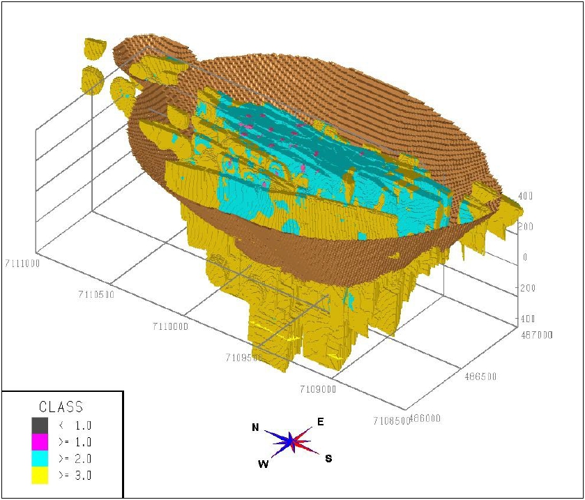
Source: MMTS, 2023
| 14.10 | Cut-off Grade and Reasonable Prospects of Eventual Economic Extraction |
Net smelter price (NSP) of Au is based
on the metal prices and off-site costs in Table 14-14. The Au base case metal price used in the same as the price used for the mining
portion of this report. Prices are below the three year trailing average price charts. The net smelter return (NSR) has been calculated
per block using the equation:
| Courageous Lake Project | Page 158 |
| Pre-feasibility Study and Preliminary Economic Assessment NI 43-101 Technical Report | January 5, 2024 |
Courageous Lake and Walsh Lake:
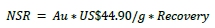
The recovery is variable by Au grade,
as summarized in Table 14 4. Open pit resources are confined by a “reasonable prospects of eventual economic extraction” shape
defined by a Lerchs-Grossman pit using the 120% case of the NSP for each deposit. The mining parameters are summarized in Table 14-14.
The base case cut-off grade is 0.80 g/t Au, which is sufficient to cover the processing cost.
| Table 14-14: | Metal Price and Net Smelter Price (NSP) |
| Parameter |
Value |
Units |
| Gold Price |
1400 |
US$/oz |
| Forex |
0.771 |
US$:C$ |
| Off-site Costs |
3.5 |
US$/oz |
| NSP |
58.23 |
US$/oz |
| Factor |
31.10348 |
grams/oz |
The final resource pits with the Au
blocks grades above the base case cut-offs are illustrated in Figure 14-10 and Figure 14-11.
| Courageous Lake Project | Page 159 |
| Pre-feasibility Study and Preliminary Economic Assessment NI 43-101 Technical Report | January 5, 2024 |
| Figure 14-10: | Courageous Lake Resource Pit and Au block Grades above
0.80 g/t |
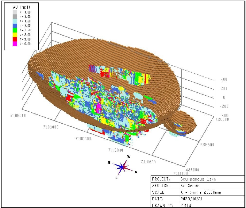
Source: MMTS, 2023
| Courageous Lake Project | Page 160 |
| Pre-feasibility Study and Preliminary Economic Assessment NI 43-101 Technical Report | January 5, 2024 |
Figure 14-11: Walsh Lake Resource Pit
and Au block Grades above 0.80 g/t
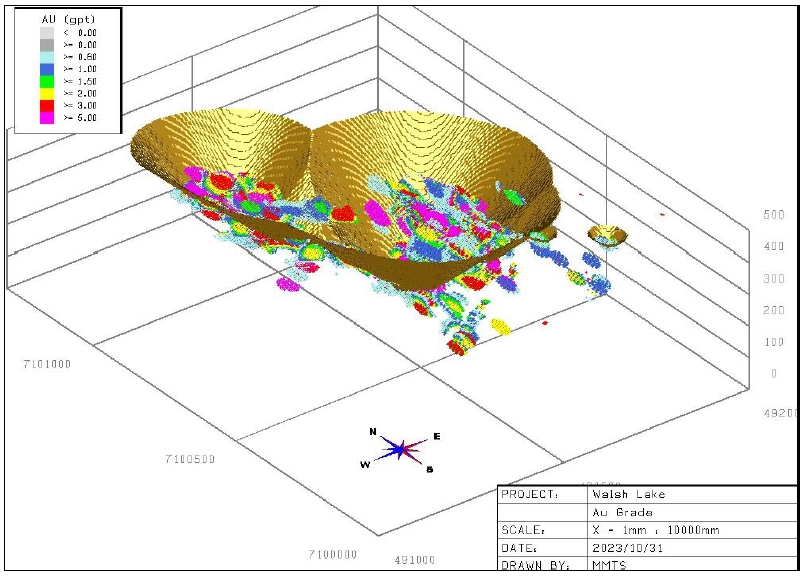
Source: MMTS, 2023
| 14.11 | Block Model Validation |
The model has been validated by comparison of the global
modelled grades with global de-clustered composites, by swath plots and by visual examination of modelled grades with assay/composite
values.
| 14.11.1 | Metal Content Validations |
The interpolated metal content has been compared to the de-clustered
composite data (Nearest Neighbor models) in all domains, and across a range of cut-off values.
| Courageous Lake Project | Page 161 |
| Pre-feasibility Study and Preliminary Economic Assessment NI 43-101 Technical Report | January 5, 2024 |
Table 14-15 compares the statistics
by domain of the global Au grades (at zero cut-off) for Courageous Lake. The weighted mean grade is 5% lower than the de-clustered composites
overall and is generally less than the composite data except for within domain 6, which is very low grade.
The modelled metal for both deposits
is summarized in Table 14-16 and Table 14-17. The tables show that at all cut-offs the modelled grades are conservative compared to the
de-clustered composites and as expected, this conservatism increases with cut-off grade.
| Table 14-15: | Interpolated Grade vs. De-clustered by Domain at zero cut-off
– Courageous Lake |
| |
Domain |
| |
|
ALL |
1 |
2 |
3 |
4 |
5 |
6 |
|
NN |
# Samples |
1,628,951 |
8,299 |
143,311 |
446,036 |
555,306 |
227,254 |
130,881 |
| # Missing |
0 |
0 |
0 |
0 |
0 |
0 |
0 |
| Min Au (g/t) |
0.001 |
0.001 |
0.001 |
0.001 |
0.001 |
0.001 |
0.001 |
| Max Au (g/t) |
147.7 |
6.3 |
9.2 |
35.8 |
147.7 |
23.6 |
4.7 |
| Wtd mean (g/t) |
0.725 |
0.422 |
0.324 |
0.683 |
1.170 |
0.513 |
0.117 |
| Wtd CV |
3.8 |
2.2 |
2.7 |
2.1 |
3.7 |
2.6 |
3.1 |
|
AU |
# Samples |
1,628,951 |
8,299 |
143,311 |
446,036 |
555,306 |
227,254 |
130,881 |
| # Missing |
0 |
0 |
0 |
0 |
0 |
0 |
0 |
| Min Au (g/t) |
0.001 |
0.001 |
0.001 |
0.001 |
0.001 |
0.001 |
0.001 |
| Max Au (g/t) |
32.4 |
4.9 |
8.9 |
16.8 |
32.4 |
23.4 |
4.4 |
| Wtd mean (g/t) |
0.707 |
0.326 |
0.313 |
0.690 |
1.115 |
0.524 |
0.121 |
| Wtd CV |
1.7 |
1.9 |
2.1 |
1.5 |
1.4 |
1.8 |
2.4 |
| Difference (%) |
-2.7% |
-22.8% |
-3.6% |
-1.1% |
4.7% |
-2.2% |
3.0% |
| Model |
Parameter |
Domain |
| 7 |
8 |
9 |
10 |
11 |
12 |
14 |
|
NN |
# Samples |
16,913 |
42,462 |
39,375 |
1,484 |
400 |
560 |
16,670 |
| # Missing |
0 |
0 |
0 |
0 |
0 |
0 |
0 |
| Min Au (g/t) |
0.001 |
0.001 |
0.001 |
0.004 |
0.001 |
0.001 |
0.001 |
| Max Au (g/t) |
5.7 |
37.3 |
7.0 |
31.9 |
4.9 |
3.6 |
5.4 |
| Wtd mean (g/t) |
0.163 |
0.815 |
0.122 |
1.416 |
0.329 |
0.354 |
0.068 |
| Wtd CV |
3.4 |
3.1 |
2.7 |
3.3 |
3.1 |
2.6 |
3.8 |
|
AU |
# Samples |
16,913 |
42,462 |
39,375 |
1,484 |
400 |
560 |
16,670 |
| # Missing |
0 |
0 |
0 |
0 |
0 |
0 |
0 |
| Min Au (g/t) |
0.001 |
0.001 |
0.001 |
0.005 |
0.002 |
0.003 |
0.001 |
| Max Au (g/t) |
4.2 |
24.1 |
2.9 |
14.2 |
2.7 |
1.9 |
1.8 |
| Wtd mean (g/t) |
0.147 |
0.769 |
0.118 |
0.925 |
0.320 |
0.256 |
0.055 |
| Wtd CV |
2.3 |
2.1 |
1.7 |
2.0 |
2.0 |
1.5 |
2.3 |
| Difference (%) |
-9.7% |
-5.8% |
-3.8% |
-34.7% |
-2.6% |
-27.6% |
-19.4% |
| Courageous Lake Project | Page 162 |
| Pre-feasibility Study and Preliminary Economic Assessment NI 43-101 Technical Report | January 5, 2024 |
| Table 14-16: | Interpolated Grade vs. De-clustered Composites by
Cut-off – Courageous Lake |
| Au
Cut-off |
|
Modelled |
|
De-Clustered
Composites (NN) |
Difference |
| (g/t) |
Tonnage
(ktonnes) |
Au
Grade (g/t) |
Au
Metal (koz) |
Tonnage
(ktonnes) |
Au
Grade
(g/t) |
Au
Metal
(koz) |
(%) |
| 0 |
732,228 |
0.667 |
15,702 |
730,294 |
0.680 |
15,959 |
-1.6% |
| 0.5 |
220,868 |
2.041 |
14,495 |
185,498 |
2.461 |
14,678 |
-1.2% |
| 0.6 |
205,287 |
2.155 |
14,221 |
170,414 |
2.631 |
14,413 |
-1.3% |
| 0.7 |
190,953 |
2.268 |
13,921 |
156,414 |
2.808 |
14,120 |
-1.4% |
| 0.8 |
177,549 |
2.382 |
13,598 |
144,661 |
2.975 |
13,836 |
-1.7% |
| 0.9 |
164,682 |
2.502 |
13,248 |
134,452 |
3.136 |
13,557 |
-2.3% |
| 1 |
153,434 |
2.616 |
12,905 |
126,345 |
3.277 |
13,310 |
-3.0% |
| 1.5 |
108,183 |
3.193 |
11,104 |
93,036 |
4.008 |
11,988 |
-7.4% |
| 2 |
75,844 |
3.814 |
9,300 |
70,331 |
4.742 |
10,721 |
-13.3% |
| 3 |
38,308 |
5.164 |
6,360 |
41,809 |
6.317 |
8,491 |
-25.1% |
| Table 14-17: | Interpolated Grade vs. De-clustered Composites by
Cut-off – Walsh Lake |
| Au
Cut-off |
|
Modelled |
|
De-Clustered
Composites (NN) |
Difference |
| (g/t) |
Tonnage
(ktonnes) |
Au
Grade (g/t) |
Au
Metal (koz) |
Tonnage
(ktonnes) |
Au
Grade (g/t) |
Au
Metal (koz) |
(%) |
| 0 |
23,051 |
0.905 |
670.6 |
23,051 |
0.948 |
702.9 |
-4.6% |
| 0.5 |
6,210 |
3.213 |
641.6 |
5,136 |
4.148 |
685.0 |
-6.3% |
| 0.6 |
5,678 |
3.463 |
632.2 |
4,754 |
4.437 |
678.2 |
-6.8% |
| 0.7 |
5,254 |
3.691 |
623.4 |
4,462 |
4.685 |
672.2 |
-7.3% |
| 0.8 |
4,935 |
3.880 |
615.6 |
4,185 |
4.946 |
665.5 |
-7.5% |
| 0.9 |
4,628 |
4.081 |
607.3 |
4,040 |
5.094 |
661.6 |
-8.2% |
| 1 |
4,342 |
4.288 |
598.5 |
3,797 |
5.358 |
654.1 |
-8.5% |
| 1.5 |
3,333 |
5.215 |
558.8 |
3,056 |
6.362 |
625.1 |
-10.6% |
| 2 |
2,678 |
6.064 |
522.1 |
2,521 |
7.341 |
595.0 |
-12.2% |
| 3 |
1,848 |
7.678 |
456.2 |
1,946 |
8.783 |
549.5 |
-17.0% |
Swath plots of the mean grade across
the model in the northing and easting directions have been created to compare the modelled Au grades with the de-clustered composite grades
throughout the model extents. Figure 14-12 and Figure 14-13 illustrate this comparison for Courageous Lake and Walsh lake respectively.
For both deposits, the modelled grade is below the de-clustered composite grade. Tonnage is also plotted to show where the majority of
the mineralization is centered in the model.
| Courageous Lake Project | Page 163 |
| Pre-feasibility Study and Preliminary Economic Assessment NI 43-101 Technical Report | January 5, 2024 |
| Figure 14-12: | Swath Plots – Courageous Lake – Au |
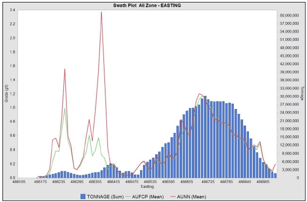
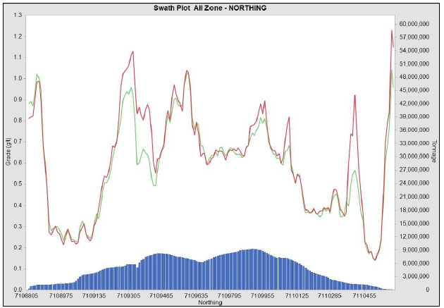
Source: MMTS, 2023
| Courageous Lake Project | Page 164 |
| Pre-feasibility Study and Preliminary Economic Assessment NI 43-101 Technical Report | January 5, 2024 |
| Figure 14-13: | Swath Plots – Courageous Lake – Au |
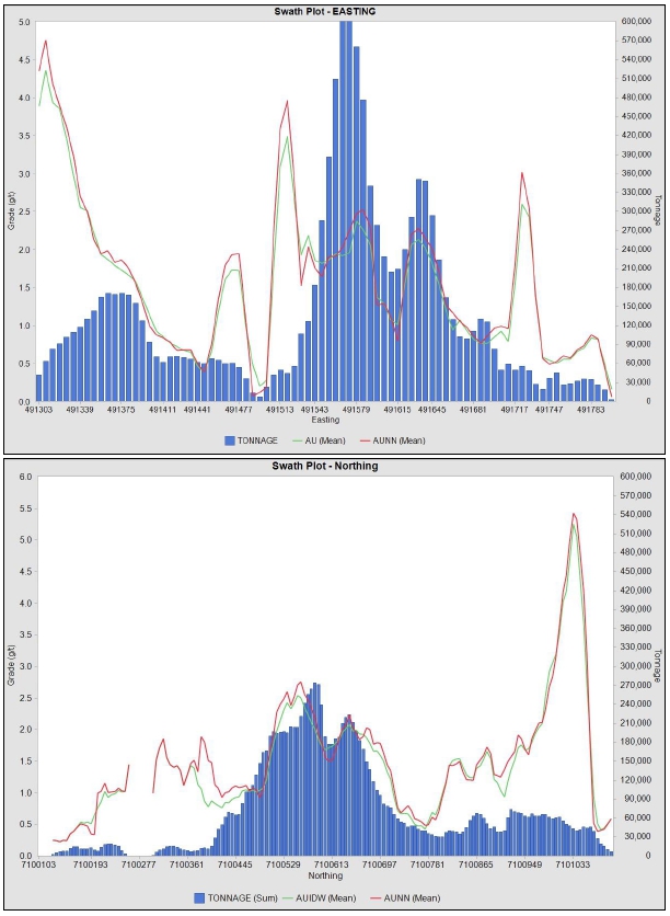
Source: MMTS, 2023
| Courageous Lake Project | Page 165 |
| Pre-feasibility Study and Preliminary Economic Assessment NI 43-101 Technical Report | January 5, 2024 |
The modelled Au grades have been compared
to the assay/composite grades in section and plan to ensure the model matches the data with no obvious discrepancies. Examples of the
sections are given in Figure 14-14 and Figure 14-15 for Au modelled at Courageous Lake, and in Figure 14-16 for Au modelled at Walsh Lake.
The composite data is plotted on the section, for better visualization, with drill hole data projected ± 25 m from the section.
| Figure 14-14: | Comparison of Composite and Block Grades – Courageous
Lake -7109400N |
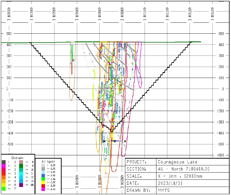
Source: MMTS, 2023
| Courageous Lake Project | Page 166 |
| Pre-feasibility Study and Preliminary Economic Assessment NI 43-101 Technical Report | January 5, 2024 |
| Figure 14-15: | Comparison of Composite and Block Grades – Courageous
Lake – 7110000N |
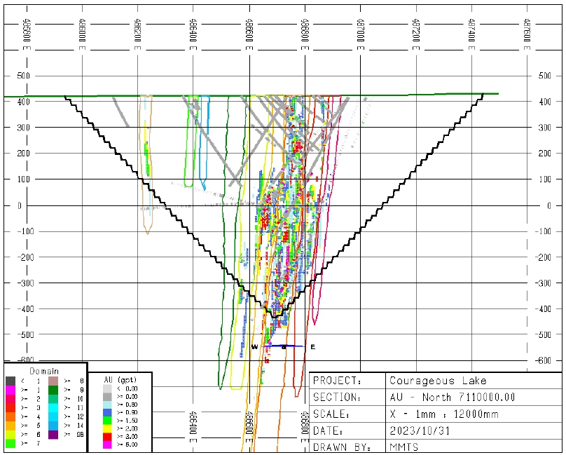
Source: MMTS, 2023
| Courageous Lake Project | Page 167 |
| Pre-feasibility Study and Preliminary Economic Assessment NI 43-101 Technical Report | January 5, 2024 |
Figure 14-16: Comparison of Composite and Block Grades
– Walsh Lake - Section 7100625
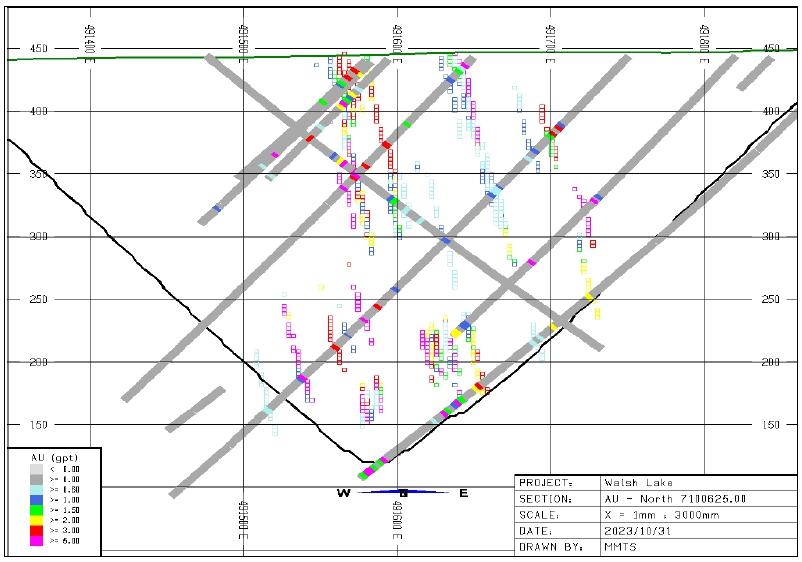
Source: MMTS, 2023
An independent check on the modelling has been done by George
Dermer, P.Eng. of MMTS who checked:
| ● | the outlier restrictions and capping for the Au interpolations |
| ● | the “reasonable prospects of eventual economic extraction” shapes
and inputs |
| ● | the nearest neighbour validations. |
| Courageous Lake Project | Page 168 |
| Pre-feasibility Study and Preliminary Economic Assessment NI 43-101 Technical Report | January 5, 2024 |
A description of potential risk factors
is given in Table 14-18 along with either the justification for the approach taken or mitigating factors in place to reduce any risk.
| Table 14-18: | Risk Factors and Justification/Mitigation |
| No. |
Description |
Justification/Mitigation |
| 1 |
Classification Criteria |
Based on variography |
| 2 |
Geologic Model |
Geologic interpretations and orientations
are considered when creating new geologic confining
shapes for the resource interpolations. |
| 3 |
Metal Price Assumptions |
Cut-off is based on a gold price well below the current prices and the 3-year trailing average. |
|
4 |
High-Grade Outliers |
Capping and outlier restriction applied
to ensure modelled mean grade matches data. Grade-
tonnage curves show modelled metal validates
well with de-clustered composite data throughout the grade distribution. |
| 5 |
Processing and Mining Costs |
Based on studies done for this report. |
| 14.15 | Modelling of Acid Rock Drainage (ARD) Elements |
At Courageous Lake, in addition to modelling
of Au, elements to aid in Au recovery estimates and potential for ARD and water quality issues have been modelled, including Sulfur (S),
Arsenic (As), Calcium (Ca), Iron (Fe) and silver (Ag). Modelling of these elements is preliminary in nature, due to intermittent assaying
of these elements causing a paucity of data throughout the modelled area.
| 14.15.1 | Correlations with Au |
In order to ‘fill’ the missing
grades in the assay database for these elements, correlations with the Au grade are attempted. Average grades by zone have been used if
correlations were not possible. Where the assay value was added through the use of correlations or averages a “Factor Flag”
was added to the assay data to indicate that there is less confidence in modelled blocks which used these factored assay values.
Table 14-19 summarizes the regressions
constants used based on plotting of au vs. each element using a linear best-fit line, where Y=mx+b. Where the slope (“m”)
value is zero, there was no correlation and therefore the mean value for the zones has been used.
| Table 14-19: | Regressions
Constants Used for As, S and Ag Asay Data Filling |
| |
Zone |
Au Grade (g/t) |
Regression
Constant |
| |
Min |
Max |
in |
Max |
“m” |
“b” |
| As (ppm) |
1 |
2 |
0 |
999 |
1448.5 |
112.2 |
| 3 |
5 |
0 |
999 |
851.9 |
478.1 |
| Courageous Lake Project | Page 169 |
| Pre-feasibility Study and Preliminary Economic Assessment NI 43-101 Technical Report | January 5, 2024 |
| |
Zone |
Au Grade (g/t) |
Regression
Constant |
| |
Min |
Max |
in |
Max |
“m” |
“b” |
| |
6 |
7 |
0 |
999 |
1145.8 |
109.4 |
| 8 |
8 |
0 |
999 |
0 |
739.8 |
| 9 |
9 |
0 |
999 |
1598.5 |
121.7 |
| 10 |
12 |
0 |
999 |
1448.5 |
112.2 |
| 14 |
14 |
0 |
999 |
1598.5 |
121.7 |
| Outside zones |
0 |
999 |
1563.5 |
36.82 |
|
S (%) |
1 |
2 |
0 |
999 |
0.1522 |
0.0889 |
| 3 |
5 |
0 |
999 |
0.0889 |
0.158 |
| 6 |
7 |
0 |
999 |
0.3069 |
0.1042 |
| 8 |
8 |
0 |
0.499 |
0 |
0.3445 |
| 8 |
8 |
0.5 |
999 |
0 |
1.0519 |
| 9 |
9 |
0 |
999 |
0.1904 |
0.0903 |
| 10 |
12 |
0 |
999 |
0.1522 |
0.0889 |
| 14 |
14 |
0 |
999 |
0.1904 |
0.0903 |
| Outside zones |
0 |
0.499 |
0 |
0.0655 |
| 0.5 |
999 |
0.0669 |
0.5 |
|
Ag (ppm) |
1 |
2 |
0 |
999 |
0.1864 |
0.2111 |
| 3 |
5 |
0 |
999 |
0.1864 |
0.2111 |
| 6 |
7 |
0 |
999 |
0.1384 |
0.2452 |
| 8 |
8 |
0 |
999 |
0.1384 |
0.2452 |
| 9 |
9 |
0 |
999 |
0.1384 |
0.2452 |
| 10 |
12 |
0 |
999 |
0.1864 |
0.2111 |
| 14 |
14 |
0 |
999 |
0.2119 |
0.2568 |
| Outside zones |
0 |
999 |
0.1808 |
0.2091 |
| Table 14-20: | Mean Value by
Zone used for Fe and Ca Assay Data Filling |
| |
Average
Grade |
| |
Fe
(%) |
Ca
(%) |
| 1 |
1.919 |
2.082 |
| 2 |
2.078 |
2.025 |
| 3 |
2.037 |
2.227 |
| 4 |
2.057 |
2.076 |
| 5 |
1.735 |
2.022 |
| 6 |
2.173 |
2.268 |
| 7 |
2.94 |
2.315 |
| Courageous Lake Project | Page 170 |
| Pre-feasibility Study and Preliminary Economic Assessment NI 43-101 Technical Report | January 5, 2024 |
| |
Average
Grade |
| |
Fe (%) |
Ca (%) |
| 8 |
3.611 |
2.221 |
| 9 |
1.977 |
2.153 |
| 10 |
1.919 |
2.082 |
| 11 |
1.919 |
2.082 |
| 12 |
1.919 |
2.082 |
| 14 |
2.055 |
1.859 |
| Outside zones |
2.004 |
2.271 |
| 14.15.2 | ARD Item Interpolations |
Interpolations followed
the same interpolation parameters and break-up of zones as was used for the Au interpolations. Table 14-11 summarizes the basic parameters
that were used to estimate block gold grades for mineral zones 2 through 6 and 8. Inverse distance cubed estimation parameters for mineral
zones 1, 7, 9, 12, are 14, are summarized in Table 14-12 and for Domains 10 and 11 in Table 14-12.
The initial interpolations have been
done using only the actual data (no factored assay/composite values used). Additional passes of the interpolation are then done using
both the factored and actual data. Blocks that were still not interpolated then had the mean grade of that zone’s data for each
element assigned. A flag is used in the model to denote whether only actual data has been used (FLAG=1), if factored data was also used
(FLAG=2) or if mean values were assigned by zone (FLAG=3), thus denoting the relative confidence in the block grade estimation. Table
14-21 summarizes the mean grades used to fill the un-interpolated blocks in each zone. It should be noted that Zones 10 through 12 do
not have any assay values for these items. Therefore, the correlation equations and mean values for Zones 1 have been used to model these
zones.
There has been no capping or outlier
restriction used for these ARD item’s interpolations, thus making these modelled items conservative as high values of sulfur tend
to decrease recovery. The models have also not been validated as the lack of data and data filling steps required to alleviate this issue
are not amenable to creating validated models for these items. However, with the possible exception of As, the assay values are all quite
low and do not vary significantly between the zones (low SDs as summarized in the table).
| Table 14-21: | Mean Grades
of ARD Items – Used to Fill Un-interpolated Blocks |
| |
Mean
Grade to Assign |
| |
As
(ppm) |
Ca
(%) |
S
(%) |
Fe
(%) |
Ag
(ppm) |
| 1 |
322.63 |
2.082 |
0.1116 |
1.919 |
0.29 |
| 2 |
542.06 |
2.025 |
0.1346 |
2.078 |
0.28 |
| 3 |
1019.91 |
2.227 |
0.2095 |
2.037 |
0.35 |
| 4 |
1297.25 |
2.076 |
0.2455 |
2.057 |
0.59 |
| Courageous Lake Project | Page 171 |
| Pre-feasibility Study and Preliminary Economic Assessment NI 43-101 Technical Report | January 5, 2024 |
| |
Mean
Grade to Assign |
| |
As
(ppm) |
Ca
(%) |
S
(%) |
Fe
(%) |
Ag
(ppm) |
| 5 |
948.02 |
2.022 |
0.2006 |
1.735 |
0.37 |
| 6 |
253.02 |
2.268 |
0.1119 |
2.173 |
0.23 |
| 7 |
153.56 |
2.315 |
0.1739 |
2.94 |
0.29 |
| 8 |
739.79 |
2.221 |
0.4743 |
3.611 |
0.29 |
| 9 |
479.35 |
2.153 |
0.1441 |
1.977 |
0.29 |
| 10 |
322.63 |
2.082 |
0.1116 |
1.919 |
0.29 |
| 11 |
322.63 |
2.082 |
0.1116 |
1.919 |
0.29 |
| 12 |
322.63 |
2.082 |
0.1116 |
1.919 |
0.29 |
| 14 |
183.91 |
1.859 |
0.0843 |
2.055 |
0.24 |
| Outside zones |
78.99 |
2.271 |
0.0695 |
2.004 |
0.24 |
| Standard deviation |
366.94 |
0.12 |
0.10 |
0.50 |
0.09 |
| Courageous Lake Project | Page 172 |
| Pre-feasibility Study and Preliminary Economic Assessment NI 43-101 Technical Report | January 5, 2024 |
| 15 | MINERAL RESERVE ESTIMATES |
Mineral reserves are based on modifying
factors applied to measured and indicated mineral resources within a pre-feasibility mining study (PFS).
| 15.2 | Open Pit Reserve Parameters |
The mining modifying factors are described
in Section 16 and can be found as follows:
| ● | Metal prices, offsite costs, recoveries and exchange rates – Section
16.13. |
| ● | Loss and dilution factors – Section 16.14. |
| ● | Economic pit limit analysis – Section 16.16. |
| ● | Detailed pit designs – Section 16.17. |
| ● | Mine plan – Section 16.18. |
Only Measured and Indicated Resources
are considered for conversion to Mineral Reserves. Inferred Resources are considered as waste. Mineral Reserves in this 2024 PFS have
been limited to the depth of the expected permafrost (335 m below topography).
The cut-off grade used to define ore
(inside of the economic pit limit) is NSR >= C$49.66/t milled. The NSR cut-off grade considers an estimated process operating cost
of C$31.40/t milled + G&A costs of C$18.26/t milled. The calculation of NSR values used for mine planning is described in Section
16.
Proven and probable mineral reserves
are summarized in Table 15-1 and match the production plan described in Section 16. The (QP is not aware of any other risks, other than
those identified in this report, that could materially affect the mineral reserve estimates.
| Courageous Lake Project | Page 173 |
| Pre-feasibility Study and Preliminary Economic Assessment NI 43-101 Technical Report | January 5, 2024 |
| Table 15-1: | Proven and Probable Reserves |
| Reserve
Class |
Ore
(Mt) |
Diluted
Au Grade (g/t) |
Contained
Gold (Moz) |
| Proven |
2.0 |
3.5 |
0.2 |
| Probable |
31.9 |
2.6 |
2.6 |
| Proven + Probable |
33.9 |
2.6 |
2.8 |
Notes:
| 1. | The Mineral Reserve estimates were reviewed by Jesse Aarsen, P.Eng. (who is also the independent QP for these Mineral Reserve estimates),
reported using the 2014 CIM Definition Standards and 2019 CIM Best Practices Guidelines, and have an effective date of January 5, 2024 |
| 2. | Mineral Reserves are based on the 2024 PFS open pit life of mine plan |
| 3. | Mineral Reserves are mined tonnes and grade; the reference point is at the primary crusher and includes consideration for operational
modifying factors |
| 4. | Mineral reserves are reported at NSR cut-off grade C$49.66/tonne: metal prices of US$1,400/oz Au, at a
currency exchange rate of US$0.77 per C$; Off-site costs (smelting, refining, transport, and insurance) doré terms are US$3.5/oz
off-site costs (refining, transport and insurance), 100% Au payable; metallurgical recovery projections vary depending on metallurgical
domain and metal grades and are based on metallurgical test work |
| 5. | Mineral Reserves account for mining loss and dilution |
| 6. | Mineral Reserves are a subset of the Measured and Indicated Mineral Resource |
| 7. | Numbers have been rounded |
Twenty-four percent of the Mineral Resources are converted
into Mineral Reserves.
| 15.4 | Factors that Could Affect the Mineral Reserve Estimate |
Mineral reserves are based on the engineering and economic
analysis described in Sections 16 to 22 of this report. Changes in the following factors and assumptions could affect the mineral reserve
estimate:
| ● | Assumptions on weather and climate. |
| ● | Effects of climate change, resulting in changes to the depth of permafrost. |
| ● | Interpretations of mineralization geometry and continuity of mineralization
zones. |
| ● | Interpolation of grade parameter assumptions. |
| ● | Geotechnical and hydrogeological assumptions. |
| ● | Operating cost assumptions and price escalation. |
| ● | Process plant and mining recoveries. |
| ● | Ability to meet and maintain permitting and environmental license conditions. |
| ● | Ability to maintain the social license to operate. |
| 15.5 | Comments on Section 15 |
The current mineral reserve estimates are
based on the most current knowledge, permit status, and engineering constraints. The QP is of the opinion that the mineral reserves
have been estimated using industry best practices.
| Courageous Lake Project | Page 174 |
| Pre-feasibility Study and Preliminary Economic Assessment NI 43-101 Technical Report | January 5, 2024 |
Tetra
Tech (2023b) completed an updated pre-feasibility level pit slope design criteria for the proposed Courageous Lake open pit based on
geotechnical, hydrogeological, ground temperature, laboratory strength testing, and water quality studies that have been completed at
the project site since 2006. This included updated bench design and slope stability assessments using limit equilibrium methods applied
to 2D cross sections through different pit quadrants. The geotechnical, hydrogeological, and permafrost investigations, and the subsequent
rock slope design studies by Tetra Tech have been completed in general accordance with the requirements for a Level 2: Pre-feasibility
slope angle study as described in “Guidelines for Open Pit Slope Design” (Read and Stacey 2009). Tetra Tech used established
pit slope design methods for bench scale and overall slope design consistent with current industry practice guidelines. A 3D hydrogeological
model was developed using the hydrogeological testing data collected and using established groundwater modelling computer software in
order to consider the possible impact of elevated groundwater pressures on pit slope stability, as well as to estimate possible water
inflow quantities and water quality to the pit.
The
geotechnical data collected to support the pit slope design study follows industry standard data collection methods for rock mass characterization
and open pit slope design. Field and laboratory sample collection, preparation, and testing was carried out in general accordance with
International Society of Rock Mechanics (ISRM) Suggested Methods and/or ASTM Standards for testing of rock core samples and soil samples.
| 16.2 | Geotechnical,
Hydrogeological, Ground Temperature, and Laboratory Testing Programs |
The
field investigations on which the pre-feasibility level pit slope designs are based are described below.
EBA
completed a geotechnical drilling investigation for pit slope design in 2006 consisting of the following:
| ● | Geotechnical
logging and sampling of seven inclined boreholes. Oriented core was not successful for all
core intervals. |
| ● | Point
load testing (PLT) on 157 samples at EBA’s rock laboratory in Whitehorse. |
| ● | Installation
of two ground temperature cables (GTCs). |
| 16.2.2 | 2010
Geotechnical, Hydrogeological, and Permafrost Field Studies |
Geotechnical,
permafrost, ground temperature, and hydrogeological field studies were completed at the site by Golder and EBA including:
| ● | geotechnical
logging of specific intervals of 5 non-oriented exploration boreholes drilled using NQ coring; |
| Courageous Lake Project | Page 175 |
| Pre-feasibility Study and Preliminary Economic Assessment NI 43-101 Technical Report | January 5, 2024 |
| ● | geotechnical
logging and packer testing in 3 oriented geotechnical boreholes; |
| ● | point
load strength tests of rock cores every 10 m in accordance with ISRM suggested methods; |
| ● | geotechnical
mapping of a surface quarry named Peggy’s Pit; |
| ● | 10
soil geotechnical boreholes for surface infrastructure, soil descriptions, installation of
two GTCs, and laboratory grain size and index testing of soil samples; |
| ● | unconfined
compressive strength testing (15 rock core samples); |
| ● | direct
shear testing of 9 samples (6 foliation and 3 joint surfaces); |
| ● | eight
hydraulic conductivity (packer) testing of the sub-permafrost aquifer in two boreholes; |
| ● | two
GTCs in two of the geotechnical boreholes; |
| ● | one
vibrating wire piezometer in the sub-permafrost aquifer; |
| ● | two
electrical conductivity probes for preliminary water quality estimation; and |
| ● | a
site visit by a senior pit slope engineer. |
| 16.2.3 | 2011
and 2012 Geotechnical, Hydrogeological, and Permafrost Field Studies |
In 2011 Golder
and EBA completed geotechnical, permafrost, and hydrogeological field studies were completed at the site. The field programs included:
| ● | geotechnical
core logging of two inclined HQ3 boreholes with core orientation using the Reflex ACTII orientation
tool including wet and dry core photography; |
| ● | unconfined
compressive strength testing (17 rock core samples); |
| ● | direct
shear strength testing (15 discontinuity surfaces); |
| ● | point
load testing of core samples every 25 m in accordance with ISRM suggested methods; |
| ● | nine
hydraulic conductivity testing the two geotechnical boreholes; |
| ● | 14
soil geotechnical boreholes for surface infrastructure using chilled brine to collect permafrost
soil samples for logging and testing, permafrost and soil logging, moisture content determinations,
grain size gradations, and installation of 3 additional GTCs; |
| ● | additional
data from two GTCs installed by Golder during the 2010 summer geotechnical program and from
one GTC installed by EBA during the 2006 summer geotechnical program; |
| ● | data
from one vibrating wire piezometer installed by Golder during the 2010 summer geotechnical
program; |
| ● | assistance
with installation and development of two Westbay well installations by Schlumberger Canada
Ltd (SLB) and Rescan Environmental Services Ltd (Rescan) in 2011 and 2012. |
| Courageous Lake Project | Page 176 |
| Pre-feasibility Study and Preliminary Economic Assessment NI 43-101 Technical Report | January 5, 2024 |
| Figure 16-1: | Summary of Geotechnical, Hydrogeological
and Ground Temperature Investigations |
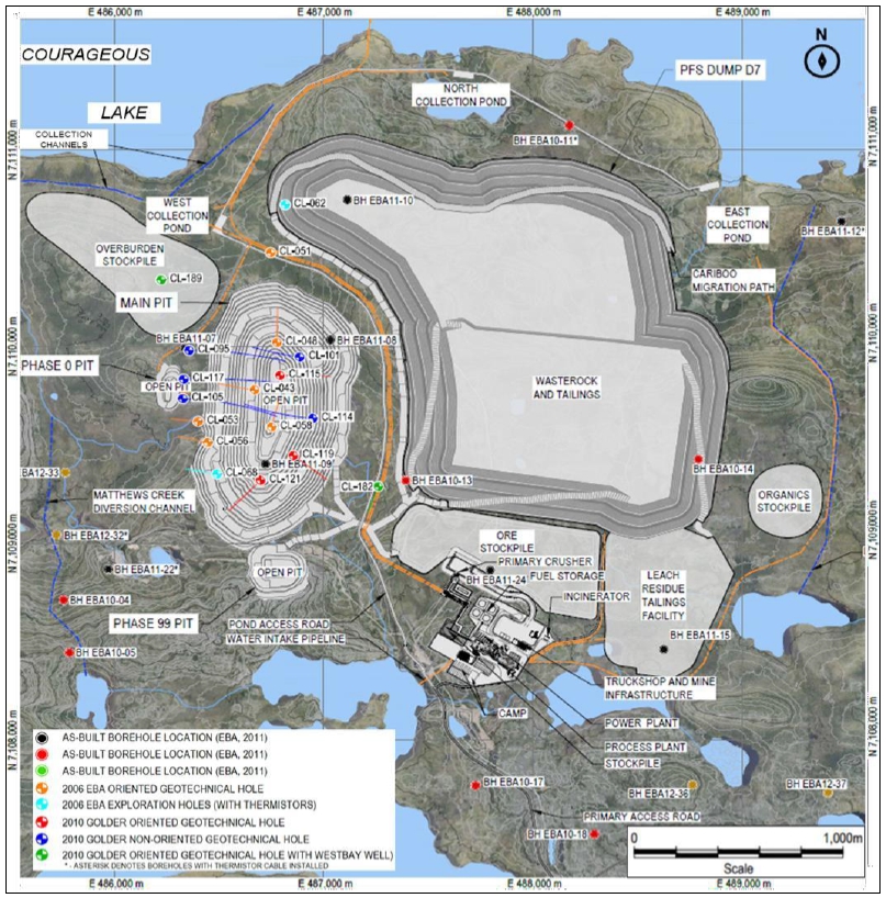
Source: TetraTech,
2023
| Courageous Lake Project | Page 177 |
| Pre-feasibility Study and Preliminary Economic Assessment NI 43-101 Technical Report | January 5, 2024 |
| 16.2.4 | General
Geological Setting, Site Geology, and Structure |
The
proposed pit is expected to be excavated predominantly in the variably altered felsic volcanic rocks (FEL) of the Courageous-MacKay Lake
Greenstone Belt (CLGB) volcanic sequence. The felsic volcanic rocks are composed of massive to porphyritic flows, tuff, and coarse pyroclastic
units. The upper volcanic sequences which interfinger with the overlying Yellowknife Group Sedimentary (YGS) rocks are host to nearly
all the gold mineralization. Tilting of the stratigraphy has resulted in steeply dipping, elongate lenticular mineralized zones within
Archean tuffaceous clastic rocks and ash-flow tuff.
The
Tundra Shear Zone is a fault that will intersect the east and west walls of the pit. It is interpreted to be steeply west dipping and
striking into the east and west walls at a relatively high angle.
The
mineralized domains are contained in the mineral zone within an upper felsic volcanic unit and comprise several discrete, steeply west
dipping ore zones that vary in thickness from 20 to 125 m wide.
| 16.2.5 | Permafrost,
Groundwater, and Water Quality |
The
Project is located within the zone of continuous permafrost and has been characterized by the installation of shallow and deep GTCs from
134 m to 450 m below ground surface. The deeper permafrost regime below the active layer and within bedrock is estimated to vary in depth
from 335 to 422 based on the GTCs, but could be as shallow as 287 m below ground surface in certain areas. For hydrogeological and geotechnical
modelling purposes a base case depth is assumed to be 335 m. The permafrost conditions are shown conceptually in Figure 16-2.
A
basal cryopeg is interpreted at the transition from the permafrost to the sub-permafrost groundwater flow regime, consisting of a zone
of sub-zero ground temperatures (e.g., permafrost) within which liquid groundwater can still be present due to the freezing point depression
caused by high groundwater salinity and hydrostatic pressure. Within this zone, groundwater inflows to the pit and high groundwater pressures
behind the pit walls and below the pit floor can develop and this was considered in the stability analyses and water quality and quantity
predictions.
| Courageous Lake Project | Page 178 |
| Pre-feasibility Study and Preliminary Economic Assessment NI 43-101 Technical Report | January 5, 2024 |
| Figure 16-2: | Conceptual Permafrost Conditions
for the Courageous Lake Project |
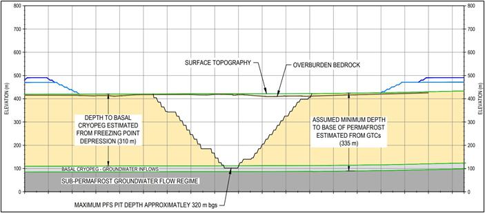
Source: TetraTech,
2023
| 16.3 | Groundwater
Pressures, Pit Water Inflows, Water Management, and Slope Depressurization |
The
data from 17 hydraulic conductivity tests and one vibrating wire piezometer were used by WSP to build a 3D hydrogeological numerical
model to simulate groundwater pressures in the pit walls, water quality (TDS) and quantity, and preliminary dewatering/depressurization
plans including the number of pumping wells, well depths, and pumping rates. The water quality was based on water samples collected from
two Westbay wells installed to target depths of 625 m bgs. TDS from Intervals 2 and 3 of the Westbay 2 well were in the range of 8215
(Interval 3 at 493 m depth) to 9495 (Interval 2 at 553 m depth) mg/L indicating the sub-permafrost groundwater to be highly saline.
| 16.4 | Open
Pit Rock Slope and Overburden Design Recommendations |
| 16.4.1 | Rock
Slope Design Basis |
The
pit slope design incorporates the following considerations:
| ● | The
maximum pit depth is 320 m. |
| ● | The
operational benches are 10 m high with final bench heights of 20 m. |
| ● | High-quality
controlled trim blasting methods with a pre-shear row using angled blast holes will be used
to shape final bench face geometries accounting for the orientations of controlling rock
fabric and structure. |
| Courageous Lake Project | Page 179 |
| Pre-feasibility Study and Preliminary Economic Assessment NI 43-101 Technical Report | January 5, 2024 |
| ● | The
geology and structure of the pit area is relatively uncomplicated and is inclined at relatively
steep angles to the west parallel to a dominant west dipping foliation structure. |
| ● | The
general rock mass quality is ‘Good’ to ‘Very Good’ based on the Rock
Mass Rating (CSIR RMR76) system (Bieniawski, 1976) as applied to the collection of geotechnical
data from rock cores. |
| ● | The
rock is classified as Strong to Very Strong and, in some cases, Extremely Strong based on
the International Society of Rock Mechanics (ISRM) rating system, and the results of laboratory
strength testing. |
| ● | The
majority of the pit slopes will be excavated within permafrost, and no major facilities will
be located immediately behind the crest. |
| ● | The
depth to the base of permafrost is estimated to be 335 m, but could be as shallow as 287
m. |
| ● | A
transition zone (basal cryopeg) from the permafrost frozen ground to the sub-permafrost groundwater
aquifer will be present at an estimated depth of 310 m bgs and thickness of 25 m during mining
of the final benches and contribute to elevated pore-pressures at the toe of the slope and
in the base of the pit. |
| ● | Groundwater
pressures within the portions of the pit walls excavated in permafrost will be negligible,
except within the basal cryopeg. |
| 16.4.2 | Geotechnical
Domains and Design Sector Definitions |
The
main deposit area is currently defined as a single geotechnical (structural) domain characterized by the steeply west dipping foliation,
a flat lying joint set, and other moderately to steeply dipping joint sets. The deposit area has been sub-divided into five Design Sectors
based on wall orientations.
Kinematic
analyses were completed for each Design Sector and bench designs were formulated to minimize bench-scale instability. The methodology
followed standard approaches for bench design, and included the following:
| ● | Cumulative
frequency analysis. |
Cumulative
frequency analysis and breakback analysis were used to estimate bench width requirements for the 20 m high final double benches. Bench
widths range from 10 m to 12 m. Based on the bench design studies, final bench face angles ranging from 64° to 80° are considered
achievable provided that high quality controlled pre-shear blasting methods are utilized for shaping final walls.
Where
the Tundra Shear Zone is exposed in the lower benches of the pit within the basal cryopeg it may be susceptible to raveling, and thus
require single bench heights for final benches to manage instability.
| Courageous Lake Project | Page 180 |
| Pre-feasibility Study and Preliminary Economic Assessment NI 43-101 Technical Report | January 5, 2024 |
| 16.5 | Inter-ramp
and Overall Slope Stability Assessment |
Tetra
Tech completed limit equilibrium modelling along six cross sections to evaluate the overall slope stability, incorporating pore pressure
predictions from a 3D hydrogeological (FEFLOW Version 8.0.2) model developed by WSP using data collected from packer testing and Westbay
Well development. The limit equilibrium stability analysis was completed using the modelling program SLIDE (Slide2 Version 9.0.028) by
RocScience. No finite element modelling was completed for the pre-feasibility design study but should be considered for future design
studies. A Base Case stability model was established, and a series of sensitivity analyses were developed in addition to the Base Case
to test the sensitivity of the slope design criteria to uncertainty in the models and input parameters.
| 16.6 | Groundwater
Pressures and Slope Depressurization |
The
3D hydrogeological model developed by WSP was used to predict pressure heads within the sub-permafrost aquifer and basal cryopeg for
each of the stability analysis cross sections. Two cases were assessed for groundwater pressures, pit inflow quantities, water quality,
and pit depressurization requirements:
| ● | Base
case condition, with the basal cryopeg intersected at a depth of 310 m bgs. |
| ● | Sensitivity
case condition, with the basal cryopeg intersected at 262 m bgs. |
| 16.6.1 | Depressurization
Requirements and Water Quality Predictions |
The
hydrogeological model was used to estimate depressurization requirements, daily predicted inflows to the open pit and to dewatering wells,
total predicted daily inflows, and predicted TDS (mg/L). The inflows to the pit are assumed to come from the basal cryopeg and the sub-permafrost
aquifer.
The
base case depressurization condition considers 14 wells spaced at intervals of 75 to 100 m around the perimeter of the pit and installed
at elevations ranging from 125 to 185 masl. The sensitivity case depressurization condition considers 16 wells spaced at intervals of
75 to 100 m around the pit perimeter and installed at elevation 205 masl.
| 16.7 | Results
of Limit Equilibrium Slope Stability Analyses |
The
results of the stability assessment indicate that, for the base case assumptions, depressurization of the SW, W, and NW stability cross
sections is required to achieve the DAC. The sensitivity of the results to assumptions of rock bridging were assessed if the base case
without depressurization did not meet the DAC. Sensitivity analyses show that the stability results are highly sensitive to assumptions
of rock bridging applied to the main discontinuities and subordinate discontinuities. The base of permafrost, and the of the basal cryopeg,
is an undulating surface. A series of sensitivity analyses were also completed to assess the potential impact of shallower-than-expected
permafrost, basal cryopeg, and hence groundwater pressures.
| 16.8 | Overburden
Slope Design Angles |
The
recommended overburden slope design criteria included a review of laboratory testing data and moisture content determinations of
samples collected by EBA during overburden drilling investigations in 2010 and 2011, coupled with relevant experience designing
overburden slopes with similar conditions at other mine sites in the Canadian sub-arctic. The recommended maximum bench face angle
is 30°, maximum unbenched slope height of 5 m, minimum catch bench width of 5 m, and overall slope angle of 22°. Based on
the descriptions of the overburden soils from drilling, and the moisture contents, the till is generally ice-rich with ground ice
encountered within the active layer. Consequently, a minimum thermal cover thickness of 4 m should be applied to prevent the
ice-rich soils around the pit crest from thawing. The minimum toe setback of the overburden slopes from the crest of the rock slope
is 10 m.
| Courageous Lake Project | Page 181 |
| Pre-feasibility Study and Preliminary Economic Assessment NI 43-101 Technical Report | January 5, 2024 |
| 16.9 | Rock
Slope Design Angles |
The
pit slope design recommendations are predicated on minimizing undercutting of rock fabric and major structures by bench face angles,
and assume that high quality controlled blasting methods with pre-shear holes are used to shape final walls. The recommended inter-ramp
slope angles range from 42.6° to 54.6° based on wall orientation, overall slope height, pit slope design sector, and depressurization
requirements.
The
current pit design incorporates a ramp system that intersects the majority of the pit walls. Where high rock slopes are not intersected
by a ramp, the incorporation of a geotechnical step-out at 150 m to 200 m intervals is current industry practice and should be incorporated
into the next design iteration. Geotechnical step-outs should be a minimum width of 30 m to accommodate drilling equipment for the installation
of monitoring systems, radar monitoring systems, in-pit wells, and other infrastructure.
| 16.10 | Open
Pit Mining Operations Introduction |
A
PFS-level production schedule, based on an annualized average 7,500 t/d mill feed rate, has been developed for the PFS. The resulting
mine life is 12.6 years, after pre-production is completed.
In
addition to the geological information used for the block model, other data used for mine planning include the base economic parameters
(metal prices, off-site costs, consumable costs, labour rates, etc.), mining cost data derived from supplier estimates, recommended pre-feasibility
pit slope angles (PSAs), projected metallurgical recoveries, plant costs, and throughput rates.
The
2024 PFS design work is based on NAD83 coordinates. Topography is described in Section 12.7.
| 16.12 | Open
Pit Mine Planning 3D Block Model |
The
block size is 5 x 5 x 5 m with the block heights representing half a suitable bench height for the planned mining excavators, with block
dimensions suitably sized for long-range planning.
| 16.13 | Net
Smelter Return (NSR) |
NSR
per tonne (net of off-site costs and including on-site process recovery) is estimated for each block and is used as a cut-off item for
break-even ore/waste selection.
| Courageous Lake Project | Page 182 |
| Pre-feasibility Study and Preliminary Economic Assessment NI 43-101 Technical Report | January 5, 2024 |
NSR
is estimated using net smelter price (NSP) and process recovery as shown in the equation below. The NSP is based on base case gold prices;
US dollar exchange rate; and off-site costs. The final terms will be negotiated during the course of the mine development. The off-site
costs used to estimate NSP are $3.50 US$/oz. The NSR calculation is shown below:
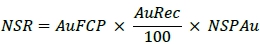
Where:
AuFCP = gold grade
(g/t) from the 3DBM item
AuRec = gold recovery (%) from the 3DBM item
NSPAu = net smelter price for gold (C$/g)
The metal prices
and resultant NSPs used at this early stage of the study are shown by pit area in Table 16-1. Note that gold NSP values are in C$/g.
| Table 16-1: | Metal Price and Resultant NSP |
| Description |
Value |
| Au
(US$/oz) |
1,400/oz |
| Exchange
Rate (US$:C$) |
0.77 |
| Au
NSP (C$/g) |
$58.23 |
Metallurgical
recoveries used for the NSR calculations are shown in Table 16-3:
| 16.14 | Mining
Loss and Dilution |
Mining
benches are 10 m high, while the model is in 5 m high blocks. Ore mining will be on split benches where required; therefore, loss and
dilution calculations are based on 5 m block sizes. Each block in the 3DBM is coded with an NSR value. Based on the cut-off grade of
NSR >= $49.66/t, which is equal to the processing + G&A cost, each block was identified as economic or uneconomic.
The
‘edge count’ method is used to quantify loss and dilution. This method examines each economic block and analyses the number
of edge contacts with uneconomic blocks (between 0 and 4) using the cut-off grade. Economic blocks with three or four uneconomic block
contacts are converted waste since the increased costs to selectively extract them outweighs their economic benefit. These ‘converted’
blocks represent some of the mining losses. All other economic blocks are defined as ore.
The
process is repeated for uneconomic blocks, counting the number of economic block contacts (between zero and four).
‘High-grade’ uneconomic blocks (NSR >= $30/t), which have three or four economic block contacts, along with all other
uneconomic blocks with four economic block contacts, are converted to ore. These ‘converted’ blocks represent dilution.
All other uneconomic blocks are defined as waste. An example of these blocks is shown in Figure 16-3.
The process is
repeated for uneconomic blocks contacting economic blocks (between 0 and 4). High-grade uneconomic blocks are defined as having an NSR
>= $30, which is close to the processing cost.
High-grade uneconomic
blocks that are contacting three or four economic blocks and all other uneconomic blocks that are contacting four economic blocks are
defined as ore (dilution). All other uneconomic blocks are defined as waste.
| Courageous Lake Project | Page 183 |
| Pre-feasibility Study and Preliminary Economic Assessment NI 43-101 Technical Report | January 5, 2024 |
| Figure 16-3: | Plan View of Losses and Dilution
Blocks |
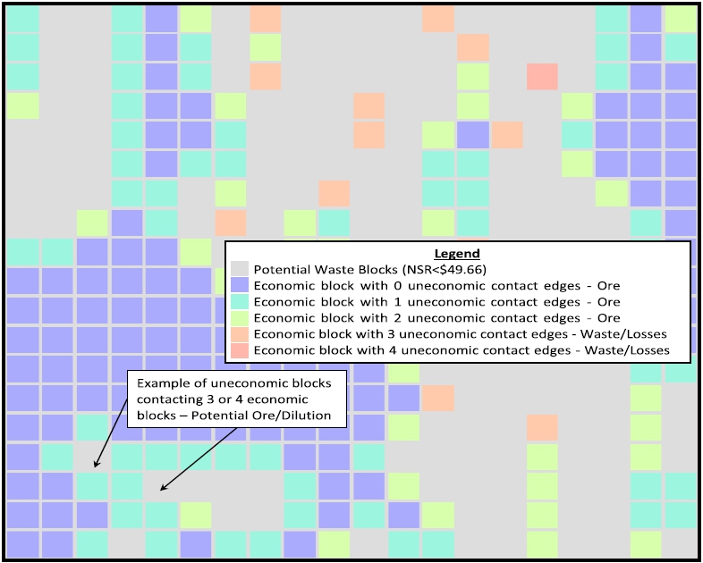
Source: MMTS,
2023
| Courageous Lake Project | Page 184 |
| Pre-feasibility Study and Preliminary Economic Assessment NI 43-101 Technical Report | January 5, 2024 |
Only measured
and indicated material is considered as ore. The overall losses and dilution are shown in Table 16-2.
| Table 16-2: | Mining Loss and Dilution for
Courageous Lake |
| |
Tonnes
(kt) |
% |
Au
Grade (g/t) |
| Losses |
4,513 |
12 |
1.91 |
| Dilution |
2,931 |
8 |
0.89 |
| 16.15 | Pit
Slope Design Angles |
See Section 16.9.
| 16.16 | Economic
Pit Limits, Pit Designs |
| 16.16.1 | Pit
Optimization Method |
The economic pit
limit is selected after evaluating LG pit cases.
The assessment
is carried out by generating sets of LG pit shells by varying revenue assumptions to test the deposit’s geometric and pit slope
sensitivity.
| 16.16.1.1 | LG Pit Assumptions |
Inputs to the
LG pit limit assessment are shown in Table 16-3 are based on the previous PFS studies (including cost escalation) as a starting point
for the 2024 design work.
| Table 16-3: | LG Pit Limit Primary Assumptions |
| Assumption |
Value |
| Mining
Cost - Waste |
C$2.75/t |
| Mining
Cost - Ore |
C$3.75/t |
| Process,
G&A, Site Services |
C$49.66/t |
| |
<0.3
g/t |
0% |
| |
0.3
g/t - 0.5 g/t |
40% |
| |
0.5
g/t - 0.75 g/t |
65% |
| Process
Recoveries |
0.75
g/t - 3.0 g/t |
76%
- 92%1 |
| |
3.0
g/t - 5.0 g/t |
93% |
| |
5.0
g/t - 8.0 g/t |
94% |
| |
<8.0
g/t |
96% |
| Pit
Slope Angle |
Variable
See Table 16-15 |
| Metal
Prices |
See
Table 16-2 |
Note :
| 1. | Between 0.75 and 3.0 g/t, Recovery
= -0.1423 x AU5 + 0.2604 x AU4 + 5.593 x AU3 - 30.217 x AU2 + 60.566 x AU + 44.935 |
LG pits are generated
by varying the NSR value from 30% to 150% of the base NSR.
| Courageous Lake Project | Page 185 |
| Pre-feasibility Study and Preliminary Economic Assessment NI 43-101 Technical Report | January 5, 2024 |
Permafrost
exists in the area to a depth of 335 m below topography. As the project area is quite flat, the base of the permafrost zone is assumed
to occur at 95 m elevation, for the entire project. The bottom section of the permafrost zone is referred to as the basal cryopeg zone.
Pockets of unfrozen groundwater will occur within the basal cryopeg zone. This water will need to be stored until mine completion, when
it can be returned to the pit. The thickness of the basal cryopeg zone is variable, and for the purpose of this study is assumed to be
50 m.
The LG shells
are constrained to stay within the permafrost zone, above 95 m elevation.
| 16.16.3 | LG
Economic Pit Limits |
The
ultimate pit shell was selected based on incremental economics, between shells. Due to the permafrost constraint, the incremental improvement
above the 60% Case provided diminishing increases in ore and value. The sensitivity of the LG economic pit limit to ore tonnes is illustrated
in Figure 16-4 where 100% represents the base case NSP parameters above. The figure was created with a $60 NSR cut-off grade, to provide
a margin for losses and dilution that were not yet calculated at this stage.
The
selected open pit limit is the 60% Case, to achieve target ounces for the project, is well within the economic limits for this study.
| Figure 16-4: | Courageous Lake Sensitivity
of Ore Tonnes to Pit Size |
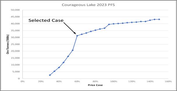
Source: MMTS,
2023
| Courageous Lake Project | Page 186 |
| Pre-feasibility Study and Preliminary Economic Assessment NI 43-101 Technical Report | January 5, 2024 |
A plan view and
north-south section views of the LG pits for the open pit mining areas are shown in Figure 16-5 and Figure 16-6.
| Figure 16-5: | Plan View of the Courageous
Lake LG Pit Limit |
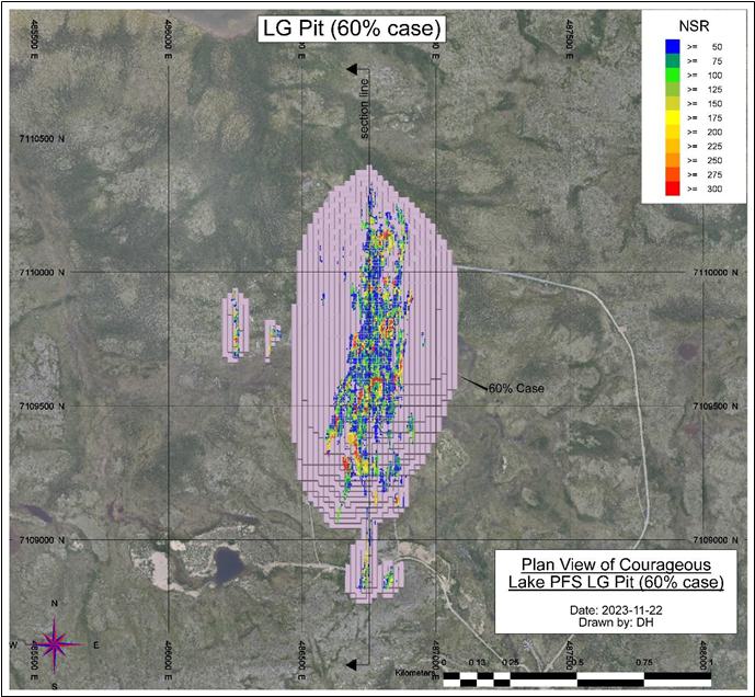
Source: MMTS,
2023
| Courageous Lake Project | Page 187 |
| Pre-feasibility Study and Preliminary Economic Assessment NI 43-101 Technical Report | January 5, 2024 |
| Figure 16-6: | Courageous Lake Economic Pit
Limit – North-South Section at East 486750 |
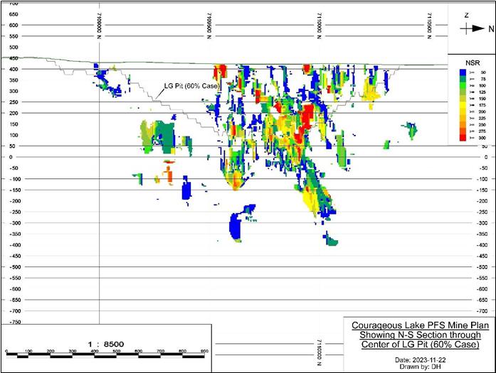
Source:
MMTS, 2023
| 16.17 | Detailed
Pit Designs |
PFS-level
pit designs demonstrate the viability of accessing and open pit mining the measured and indicated mineral resources at the Courageous
Lake site. Pit designs use the selected LG pit limits as guides as well as geotechnical parameters, suitable road widths, and minimum
mining widths based on efficient operation for the size of mining equipment chosen for the 2024 PFS.
| Courageous Lake Project | Page 188 |
| Pre-feasibility Study and Preliminary Economic Assessment NI 43-101 Technical Report | January 5, 2024 |
Haul
road widths are designed to provide safe, efficient haulage and to comply with the NWT Mines Regulations’ minimum width specifications
and safe operating practice. Haul road widths include allowance for standard double lane hauling. All roads have a maximum grade of 10%
suitable for mines with winter conditions. A sample cross section of a haul road is shown in Figure 16-7 below.
| Figure 16-7: | Double Lane Haul Road |
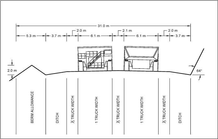
Source:
MMTS, 2023
PFS
level design parameters for the pits are provided by Tetra Tech, respectively, according to their geotechnical testing and evaluations
(Sections 16.2 and 18.7.3).
| Courageous Lake Project | Page 189 |
| Pre-feasibility Study and Preliminary Economic Assessment NI 43-101 Technical Report | January 5, 2024 |
| 16.17.2.1 | Minimum
Mining Width |
A
minimum mining width between pit phases is prescribed to maintain a suitable platform for efficient mining operations. This is established
based on equipment size and operating characteristics. For this study, the minimum mining width generally conforms to 35 m, which provides
sufficient room for 1-sided truck loading.
The
pit designs are based on the digging reach of the excavators (10 m operating bench) with double benching between high wall berms; therefore,
the berms are separated vertically by 20 m. Single bench mining will be employed, split bench mining (5 m) will be used, where required,
to maximize ore recovery and minimize dilution.
| 16.17.3 | LG
Phase Selection |
The
LG selected pit cases discussed previously are used to evaluate alternatives for determining the economic pit limit and the optimal pushbacks
or phases before commencing detailed design work.
There
are smaller pit shells within the economic pit limits that have higher economic margins, due to lower strip ratios or better grades than
the full economic pit limit. Mining these pits as phases from higher to lower economic margins helps to increase early revenue and reduce
early mining costs.
The
Courageous Lake pit has four incremental phases (1-4), and two satellite phases (0 and 99). Phases 0 and 99 are standalone phases and
are designed to provide pre-production start-up and construction material, as well as a location for water storage when the Basal Cryopeg
is mined, later in the mine life. Phase 1 is the in the center of the ultimate pit, and provides low strip ratio, higher grade feed at
the beginning mining. Phase 2 mines the south of the ultimate pit. Phase 3 mines the northeast of the ultimate pit. Phase 4 mines the
northwest of the pit, as well as the pit bottom.
A
plan view of the Courageous Lake pit phases is shown in Figure 16-8. Table 16-4 shows the ore and waste tonnes, grade, and strip ratio
by phase.
| Courageous Lake Project | Page 190 |
| Pre-feasibility Study and Preliminary Economic Assessment NI 43-101 Technical Report | January 5, 2024 |
| Figure 16-8: | Plan View of Courageous Lake
Pit Phases |
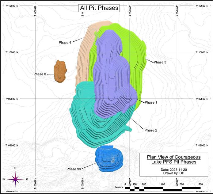
Source: MMTS,
2023
| Courageous Lake Project | Page 191 |
| Pre-feasibility Study and Preliminary Economic Assessment NI 43-101 Technical Report | January 5, 2024 |
| Table 16-4: | Pit Phase Inventories |
| |
Ore |
Waste |
Total
Material |
| |
kTonnes |
Diluted Au (g/t) |
kTonnes |
kTonnes |
Strip Ratio (t:t) |
| Phase 0 |
142 |
5.18 |
967 |
1,109 |
6.8 |
| Phase 1 |
11,390 |
2.90 |
47,890 |
59,280 |
4.2 |
| Phase 2 |
5,502 |
2.49 |
64,352 |
69,854 |
11.7 |
| Phase 3 |
3,353 |
2.52 |
48,752 |
52,105 |
14.5 |
| Phase 4 |
13,175 |
2.41 |
91,209 |
104,384 |
6.9 |
| Phase 99 |
359 |
2.32 |
3,862 |
4,221 |
10.7 |
| Grand Total |
33,922 |
2.61 |
257,032 |
290,954 |
7.6 |
| 16.18.1 | LOM
Open Pit Production Schedule |
The
open pit mine production schedule is developed with Hexagon’s MinePlan Strategic Optimizer (MPSO), a comprehensive long-range schedule
optimization tool for open pit mines used to produce a LOM schedule that increases the NPV of the PFS.
In
the open pit mine schedule, “Time 0” refers to the mill start date; mill feed production starts in Year 1 and full mill feed
production is reached in Year 2. The production schedule specifies:
| ● | pre-production:
Year -1. |
| ● | first
year of production: Year 1. |
| 16.18.1.1 | Open Pit Mine Load
and Haul Fleet Selection |
The
mine load and haul fleet are selected prior to production scheduling. All equipment is diesel powered, as the site does not have a connection
to an electrical grid.
12
m3 bucket diesel hydraulic excavator is selected as the primary digging units. Excavators are selected instead of shovels
to improve selective mining for ore and wall scaling. The excavators are paired with 90 tonne trucks for efficient loading times.
Productivities
of the selected equipment include shovel loading times, truck haul cycle estimates for multiple pit-to-destination combinations, and
appropriate spot/wait/dump times.
Autonomous
trucks are used during regular mining operations. Autonomous equipment has a lower mechanical availability (since more maintenance time
is required to maintain the technology on board) but a higher operator efficiency and increased operating hours per day (no breaks or
shift-change delays). Standard delays such as blasting, fueling, clean-up, long moves, etc., are still accounted for with autonomous
units.
| Courageous Lake Project | Page 192 |
| Pre-feasibility Study and Preliminary Economic Assessment NI 43-101 Technical Report | January 5, 2024 |
| 16.18.1.2 | Schedule
Criteria |
In
order to optimize the PFS NPV, NSR grade bins are specified. This allows MPSO to develop a variable a cut-off grade strategy which increases
early mill head grades and therefore higher revenues in the early years of production. Phase precedence is specified based on the logical
progression of phase geometry (no undermining is allowed).
The
primary program objective in each period is to maximize the NPV. The MPSO NPV calculation is guided by estimated operating and capital
costs, process recoveries, and metal prices. Key production schedule assumptions are shown in Table 16-5.
| Table 16-5: | Production Schedule Assumptions |
| Assumption |
Value |
| Daily
Mill Throughput |
7,500
t/d |
| Haul
Truck Speed Limit |
50
km/h |
| Haul
Truck Operating Efficiency - autonomous |
94.5% |
| Dump/Maneuver/Wait
Time |
2.75
min |
| Shovel
Loading Time |
2.10
min |
| Shovel
Operator Efficiency |
95% |
| 16.18.1.3 | Cut-off
Grade Optimization |
The
sequencing of the pit phase designs typically goes from higher grades to lower, to increase mill feed grades early in the schedule and
thereby increase revenues in the earlier years. This can be further enhanced by stockpiling low-and mid-grade material for processing
at the end of the production schedule, or as needed when pit ore delivery is low; stockpiling also results in increased mining costs,
due to rehandle costs. The incremental break-even cut-off grade is set to the processing + G&A costs. Ore is binned by cut-off grades
to allow higher grade mill feed earlier and store lower grade ore in stockpiles for processing at the end of mine life. This increases
early revenues therefore increasing both the NPV and IRR.
Rock
is stored as close to the mining area as possible, East of the pit. Rock is used to build tailings impoundments, as described below.
| 16.18.2.1 | Co-Placement
Storage Facility |
The
co-placement storage facility (CPSF) is designed to act as the confinement for process tailings. The tailings will be placed in a series
of paddock systems, each paddock averaging 0.98 Mm3 of storage volume. An average tailings paddock will store six months of
tailings. Further information on the tailings paddock system is described in Section 18.
| Courageous Lake Project | Page 193 |
| Pre-feasibility Study and Preliminary Economic Assessment NI 43-101 Technical Report | January 5, 2024 |
| 16.18.2.2 | Construction
Methods |
The
CPSF uses two components which form the tailings paddock system construction, which is created in lifts from the bottom up, that alternate
between 10 and 13 m in height. The paddocks are contained within the 13 m lifts, while the 10 m lifts placed between the paddock lifts
are completely waste material. Waste not required for construction of tailings paddocks is placed directly by the haul fleet with support
from dozers as required. Waste needed to create tailings paddocks is delivered by the haul fleet to the CPSF and then stockpiled for
later placement as described in Section 18.7. When waste is used to cover a completed tailings paddock the haul trucks will dump short
of the berm and dozers will push the waste material over the tailings contained inside the paddock.
| 16.18.2.3 | Foundation
Preparation |
Design
work for CPSF foundation preparation will be performed as required. Prior to mine development, soil will be salvaged from the footprint
area where soil is suitable for reclamation purposes. Soils salvaged from the CPSF footprints will be stockpiled East of the final footprint
of the CPSF.
| 16.18.2.4 | CPSF
Access Roads |
Access
to the CPSF throughout the LOM is via a double lane, external waste haul road on the west side of the CPSF nearest to the pit exit ramp(s).
This road network also connects the mining areas with the stockpile and plant areas.
| 16.18.2.5 | Final
CPSF Configuration |
The
final CPSF for the Project is designed with overall slope angles of 21°, to accommodate the tailings paddock system. The final post-closure
configuration is adapted in accordance with the closure plan, which is further described in Section 18.7.9. A cost allowance for closure
work is included by keeping the ancillary equipment in use during later years of operation after the waste strip ratio drops to lower
levels. This allows for reclamation activities in the latter part of the mining schedule. Future studies will investigate earlier (progressive)
reclamation opportunities, as equipment becomes available from the operations. As part of the closure plan, a network of 8% grade, 30
m wide access ramps are included, which provide unimpeded right-of-way across the CPSF for the indigenous caribou population. The haul
road access forms part of this network upon closure. The caribou right-of-ways are constructed at the time of initial mine rock placement
in the CPSF to ensure immediate availability at the time of closure.
Ore
is stockpiled during the pre-stripping activity in the pre-production period. The stockpile is fed to the mill starting in Year 1. Ore
is added and removed from the stockpile, through the mine life. The residual stockpile inventory is intended for milling in Years 12
and 13 after pit mining is completed.
| Courageous Lake Project | Page 194 |
| Pre-feasibility Study and Preliminary Economic Assessment NI 43-101 Technical Report | January 5, 2024 |
| 16.18.4 | Open
Pit Mine Pre-production Detail |
Development and
pre-production activities include the following:
| ● | Mining
sufficient ore for start-up, and to support the strategy of increased feed grade in early
years, smoothing the haul fleet size over time |
| ● | Establish
mining areas that will support the equipment required to achieve ore production and annual
mill feed requirements on a sustainable basis. |
| ● | Provide
material required for construction in the mine area |
| ● | Provide
material for tailings paddock requirements in the first year of mill feed. |
| ● | Sufficient
soil stripping for dump and pit mining in Year -1 as well as Year 1 topsoil salvage and foundation
preparation: |
| ● | Construct
drainage control and water management structures |
| ● | Infrastructure
construction. |
| 16.19.1 | Year
-1 to 11 – Open Pit Mining |
The following
is a summary of mining activity in Years -1:
| ● | An
ROM ore stockpile is built in the area to north of the Mill and south of the CPSF |
| ● | All
waste material is placed in the CPSF unless required for pre-production construction |
| ● | Phase
0 is mined completely in Year -1. |
| ● | Phase
1 starts in Year -1, mining to an elevation of 385 m. |
The following is a summary of mining activity in Years 1 to 5:
| ● | Mining
in Year 1 to 5 focuses on delivering higher grade of ore to help with project payback |
| ● | All
waste material is placed in the CPSF |
| ● | Ore
is hauled directly to the Mill or stockpile |
| ● | Phase
1 is completed in Year 2 |
| ● | Phase
2 starts in Year 2 and is completed in Year 4 |
| ● | Phase
3 starts in Year 4, mining to an elevation of 385 m |
| Courageous Lake Project | Page 195 |
| Pre-feasibility Study and Preliminary Economic Assessment NI 43-101 Technical Report | January 5, 2024 |
| ● | Phase
99 is mined completely in Year 4 |
| ● | Stockpile
material is reclaimed to supplement mill feed during periods where mining is limited by periodic
large volumes of waste pre-stripping or to increase mill feed grade. |
The following
is a summary of mining activity in Years 6 to 11:
| ● | Phase
3 is completed in Year 7 |
| ● | Phase
4 starts in Year 6 and is completed in Year 11 |
| ● | All
waste material is placed in the CPSF. |
Stockpile material
is reclaimed to supplement mill feed during periods where mining is limited by periodic large volumes of waste pre-stripping or to increase
mill feed grade.
| Courageous Lake Project | Page 196 |
| Pre-feasibility Study and Preliminary Economic Assessment NI 43-101 Technical Report | January 5, 2024 |
| Figure 16-9: | End of Pre-production (Year
-1) |
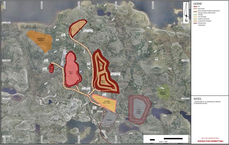
Source: MMTS, 2023
| Courageous Lake Project | Page 197 |
| Pre-feasibility Study and Preliminary Economic Assessment NI 43-101 Technical Report | January 5, 2024 |
| Figure 16-10: | End of Year 1 |
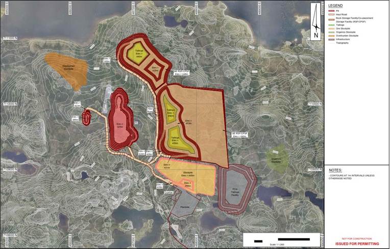
Source: MMTS, 2023
| Courageous Lake Project | Page 198 |
| Pre-feasibility Study and Preliminary Economic Assessment NI 43-101 Technical Report | January 5, 2024 |
| Figure 16-11: | End of Year 2 |
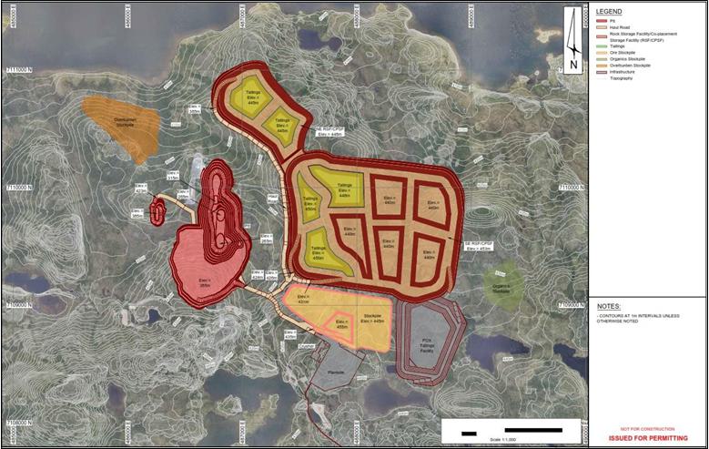
Source: MMTS, 2023
| Courageous Lake Project | Page 199 |
| Pre-feasibility Study and Preliminary Economic Assessment NI 43-101 Technical Report | January 5, 2024 |
| Figure 16-12: | End of Year 3 |
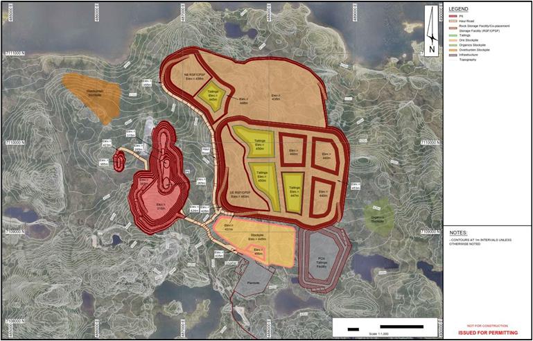
Source: MMTS, 2023
| Courageous Lake Project | Page 200 |
| Pre-feasibility Study and Preliminary Economic Assessment NI 43-101 Technical Report | January 5, 2024 |
| Figure 16-13: | End of Year 4 |
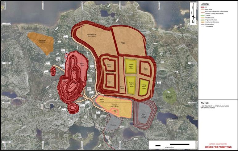
Source: MMTS, 2023
| Courageous Lake Project | Page 201 |
| Pre-feasibility Study and Preliminary Economic Assessment NI 43-101 Technical Report | January 5, 2024 |
| Figure 16-14: | End of Year 5 |
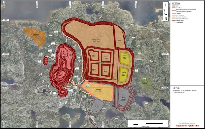
Source: MMTS, 2023
| Courageous Lake Project | Page 202 |
| Pre-feasibility Study and Preliminary Economic Assessment NI 43-101 Technical Report | January 5, 2024 |
| Figure 16-15: | Open Pit Life of Mine |
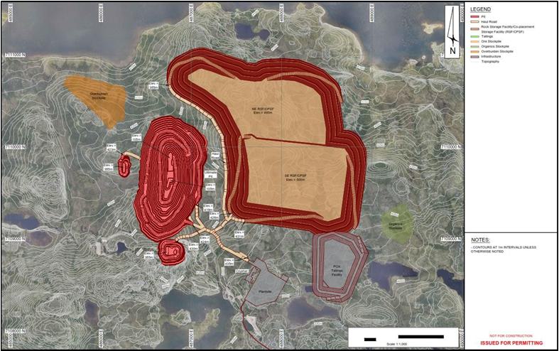
Source: MMTS, 2023
| Courageous Lake Project | Page 203 |
| Pre-feasibility Study and Preliminary Economic Assessment NI 43-101 Technical Report | January 5, 2024 |
| 16.20 | Open
Pit Mine Operations |
The
mining operations are typical of open pit operations in northern Canada and employ small scale mining equipment in waste and selective
mining in the ore zones. There is considerable operating and technical expertise, services, and support in northern Canada, especially
in the local area northeast of Yellowknife. Equipment is selected for the major operating functions in the mine (loading and hauling
waste) to generate high productivities, which helps reduce unit mining costs.
Mine
operation is organized into three areas: direct mining, mine maintenance, and general mine expense (GME).
In
this study, direct mining and mine maintenance are planned as a leased fleet with the equipment costs and labour being directly under
mine operations. The haul truck fleet will be operated as an autonomous fleet. The mine will employ the blasting crew, but supply and
on-site manufacturing of blasting materials will be contracted out. All infrastructure required for the blasting supply contractor will
be provided by the operating company.
| 16.20.2 | Direct
Mining Activities – Open Pit |
The
direct mining area accounts for the drilling, blasting, loading, hauling, and pit maintenance activities in the mine.
Blasthole
drills will be fitted with GPS navigation and drill control systems to optimize drilling. Production drills will be operated autonomously.
Diesel
hydraulic rotary drills (165 mm bit size) will be used for production drilling, both in ore and waste. Diesel hydraulic percussive drills
(50 mm bit size) will be used for controlled blasting techniques on high wall rows, pioneering drilling during pre-production, and development
of initial upper benches.
There
is an ore control drill (144 mm bit size) that will drill 3 benches (30 m) at a time for assays. The ore control drill will be utilized
in the known ore zone, as well as the ore/waste transition zone. It is assumed that 100% of ore tonnes and 25% of waste tonnes will be
drilled for ore control.
A
contract explosives supplier will provide blasting materials and technology. Due to the remote nature of the operation, an explosives
manufacturing plant will be built on site when emulsion is required. For this study, the owner provides a serviced site and all facilities
to the explosives contractor who manufactures and delivers the prescribed explosives to the blast holes and supplies all blasting accessories.
Blasting
will be done with an emulsion ammonium nitrate fuel oil blend referred to as heavy ANFO(HANFO). HANFO will be 70% emulsion 30% ANFO
for both wet and dry holes. The optimal HANFO blend and the possibility of higher use of straight ANFO with borehole liners to keep
the ANFO dry, can be investigated in future studies to reduce blasting costs.
| Courageous Lake Project | Page 204 |
| Pre-feasibility Study and Preliminary Economic Assessment NI 43-101 Technical Report | January 5, 2024 |
Blasting
accessories will be stored in magazines adjacent to the mining areas suitably located to meet federal and provincial regulations and
to avoid potential geohazards.
Loading
of the explosives will be done with bulk explosives loading trucks provided by the explosives supplier. The trucks should be equipped
with GPS guidance and should be able to receive automatic loading instructions for each hole from the engineering office. The GPS guidance
will be a necessity to be compatible with stakeless drilling.
Blast
holes will be stemmed to avoid fly-rock and excessive air blasts. Crushed rock will be provided for stemming material and will be dumped
adjacent to the blast pattern. A loader with a side dump bucket is included in the mine fleet to tram and dump the crush into the hole.
The
blasting crew will comprise mine employees and will be on day shift only. The blasting crew will coordinate drilling and blasting activities
to ensure a minimum of two weeks of broken material inventory is maintained for each excavator. Blasters will require hand-held GPS to
identify holes for pattern tie-in as blast patterns will not be staked. A detonation system will be used that consists of electric cap
initiation, detonating cord, surface delay connectors, non-electric single-delay caps, and boosters.
Ore
and waste will be defined in the blasted muck pile by ore control. A fleet management system will assist in optimizing deployment and
utilization of the mine fleet.
Two
12 m3 dipper diesel hydraulic excavator has been selected as the primary digging units. The diesel hydraulic excavators are
selected as the mine is not connected to an electrical grid. Excavators are selected instead of shovels to improve selective mining for
ore and wall scaling. A 12 m3 wheel loader will be used for stockpile management and secondary loading in the pit as required.
Minimum
bench widths of 35 m are designed to ensure sufficient operating room for loading of trucks at the excavators. Benches are designed wider
than the minimum wherever possible.
Ore
and waste will be hauled by autonomous 90 t haul trucks. Autonomous trucks are selected to reduce the camp size requirements and costs.
Haul cycle profiles are built from each bench to designated dumping points as the dump progresses. Travel times for each profile are
calculated using rimpull and braking curves provided by equipment manufacturers.
Fixed
times are calculated based on the number of passes the excavators would need to fill the trucks, as well as reasonable spot, dump, queue
and wait times. Fixed times are the same for every benches’ cycle with the same loading and hauling equipment.
| Courageous Lake Project | Page 205 |
| Pre-feasibility Study and Preliminary Economic Assessment NI 43-101 Technical Report | January 5, 2024 |
Travel
times and fixed times are added together to generate unique total haul cycle times for each bench/destination combination.
Pit
maintenance services include haul road maintenance, open pit mine dewatering, transporting operating supplies, relocating equipment,
and snow removal. Haul road maintenance is paramount to low haulage costs; dozer, and grader hours have been allocated to maintain the
haul road network throughout the LOM production schedule. A rock crusher for road grading material is included.
| 16.20.5 | Open
Pit General Mine Expense (GME) Area |
The
GME area accounts for the supervision, safety, environment, and training for the direct mining activities as well as technical support
from mine engineering and geology functions. Open pit mine operation supervision will extend down to the shift supervisor level and trainers.
GME costs also include engineering consulting expenses on an ongoing basis for specialty items, such as geotechnical and geo-hydrology
expertise, and third-party reviews in the open pit mine area.
| 16.21 | Mine
Closure and Reclamation |
Details
on mine closure and reclamation are available in Section 20.1.2.
| 16.22 | Open
Pit Mine Equipment Parameters |
Mining
equipment descriptions in this section provide general specifications so that dimensions and capacities can be determined from vendor
specification documents.
The
production requirements for the major mining equipment over the LOM are summarized in Table 16-6. The current production schedule requires
a maximum haulage fleet of 23 trucks over the LOM.
| Table 16-6: | Major Equipment Requirements |
| Major
Equipment |
Pre-production |
Year
5 |
Maximum |
| Production
Drills (165 mm holes) |
4 |
4 |
4 |
| Secondary
Drills (50 mm holes) |
2 |
2 |
2 |
| Primary
Excavator – 12 m3 Diesel Hydraulic Shovel |
2 |
2 |
2 |
| Secondary
FEL – 12 m3 |
1 |
1 |
1 |
| Haul
Truck – 90 tonne |
10 |
18 |
23 |
| Courageous Lake Project | Page 206 |
| Pre-feasibility Study and Preliminary Economic Assessment NI 43-101 Technical Report | January 5, 2024 |
Blasting assumptions
are summarized in Table 16-7. These parameters will be re-evaluated in the future with a detailed blasting study, using site-specific
rock strength parameters.
| Table 16-7: | Blasting Assumptions |
| Blasting
Pattern – Ore and Waste |
Specifications
- Dry |
Specifications
- Wet |
| Spacing |
3.9
m |
4.7
m |
| Burden |
3.9
m |
4.7
m |
| Hole
Size |
165
mm |
165
mm |
| Explosive
In-Hole Density |
0.84
g/cc |
1.25
g/cc |
| Explosive
Average Downhole Loading |
18.0
kg/m |
26.7
kg/m |
| Bench
Height |
10
m |
10
m |
| Collar |
4
m |
4
m |
| Loaded
Column |
8
m |
8
m |
| Sub-drill |
2
m |
2
m |
| Charge
per Hole |
144
kg/hole |
214
kg/hole |
| Rock
SG |
2.77
t/m3 |
2.77
t/m3 |
| Yield
per Hole |
411
t/hole |
612
t/hole |
| Powder
Factor |
0.35
kg/t |
0.35
kg/t |
| 16.22.3 | Drilling
Equipment |
Production drilling
assumptions are listed in Table 16-8.
| Table 16-8: | Open Pit Production Drilling
Assumptions |
| Parameter |
Diesel
Rotary |
| Bench
Height |
10
m |
| Subgrade |
2
m |
| Hole
Size |
165
mm |
| Effective
Penetration Rate (including efficiencies) |
28
m/h |
| Hole
Depth |
12
m |
| Setup
Time |
2.0
min |
| Drill
Time |
25.7
min |
| Move
Time |
4.0
min |
| Total
Cycle Time |
29.7
min |
| Holes
per Hour |
2.02 |
| Re-drills |
5% |
| Courageous Lake Project | Page 207 |
| Pre-feasibility Study and Preliminary Economic Assessment NI 43-101 Technical Report | January 5, 2024 |
A 50 mm diesel
percussive drill is also specified for controlled blasting techniques on high wall rows in all pit phases, pioneering drilling during
pre-production, and development of initial upper benches.
| 16.22.3.1 | Open Pit Dewatering
Equipment |
The dewatering
activities will include vertical dewatering wells, as well as in-pit sumps. Pit water will be collected and stored in either the mined-out
Phase 0 or mined-out Phase 99, as available.
| 16.22.4 | Open
Pit Support Equipment |
The mine support
equipment fleet requirements are summarized in Table 16-9. The fleet size in Year 5 is shown as representative of the LOM requirement.
| Table 16-9: | Mine Support Equipment Fleet |
| Fleet |
Function |
Year
5 |
| Track
Dozer – 450 kW |
Pit
Support and Dump Maintenance |
2 |
| Track
Dozer – 325 kW |
Pit
Support |
1 |
| Rubber
Tired Dozer – 370 kW |
Pit
Clean-Up |
1 |
| Fuel/Lube
Truck |
Shovel
and Drill Fueling and Lube |
2 |
| Excavator
- 3 m3 bucket |
Pit
Support and Dewatering |
1 |
| Excavator
- 4 m3 bucket |
Pit
Support and Dewatering |
1 |
| Wheel
Loader – 4 m3 bucket |
Pit
Clean-Up |
1 |
| Articulated
Truck - 40 t |
Road
Maintenance |
2 |
| Water
Truck – 12,000 gal |
Haul
Roads Water Truck |
2 |
| Motor
Grader – 216 kW |
Road
Grading |
2 |
| Tire
Manipulator |
Tire
Changes |
2 |
| 16.22.5 | Open
Pit Ancillary Equipment |
The mine ancillary
equipment fleet includes such equipment as excavators, mine rescue trucks, picker trucks, cranes, snowcats, forklifts, service trucks,
welding trucks, sump pumps and float trucks.
| Courageous Lake Project | Page 208 |
| Pre-feasibility Study and Preliminary Economic Assessment NI 43-101 Technical Report | January 5, 2024 |
| 16.22.6 | Open
Pit Ancillary Facilities |
| 16.22.6.1 | Shops and Offices |
In
addition to providing an area for maintenance bays, tire shops, and a wash bay, the maintenance shop will also house:
| ● | offices
for administration, mine supervision, and engineering/geology staff |
| ● | a
lunchroom and supervisor’s office. |
The
recommended shop sizing for the open pit operations includes service bays, welding bay, and wash bay. This will accommodate the fleet
for the LOM PFS production plan. The mine maintenance facility will also include a machine shop area, tool storage area, mine muster
area, warehouse, and office complex. A separate tire bay facility will be required to accommodate a truck and a tire manipulator.
| 16.23 | Mine
Production Schedule |
The
summarized production schedule results are shown in Table 16-10 and Figure 16-16. Pre-stripping will use the owner’s personnel
and mining fleet in the pre-production years. After mill start-up, a variable cut-off grade strategy is used to enhance revenues for
a minimum capital payback period. The variable cut-off strategy stockpiles lower grade material early in the mine life.
| Courageous Lake Project | Page 209 |
| Pre-feasibility Study and Preliminary Economic Assessment NI 43-101 Technical Report | January 5, 2024 |
| Table 16-10: | Summarized Production Schedule |
| |
|
Year |
-1 |
1 |
2 |
3 |
4 |
5 |
6 |
7 |
8 |
9 |
10 |
11 |
12 |
13 |
LOM |
| Pit to Mill |
Amount |
Mt |
|
2.12 |
1.86 |
1.36 |
1.73 |
0.49 |
2.32 |
0.84 |
1.37 |
2.74 |
2.74 |
1.42 |
0.00 |
0.00 |
18.97 |
| Au |
g/t |
|
5.47 |
3.78 |
3.18 |
3.16 |
2.63 |
2.68 |
2.41 |
2.37 |
2.69 |
3.45 |
3.03 |
0.00 |
0.00 |
3.28 |
| Pit to Stockpile |
Amount |
Mt |
2.73 |
4.32 |
1.37 |
1.01 |
0.94 |
0.21 |
0.18 |
0.07 |
0.10 |
0.64 |
3.12 |
0.27 |
0.00 |
0.00 |
14.95 |
| Stockpile Reclaim |
Amount |
Mt |
|
0.08 |
0.88 |
1.38 |
1.01 |
2.25 |
0.42 |
1.90 |
1.37 |
0.00 |
0.00 |
1.32 |
2.74 |
1.59 |
14.95 |
| Au |
g/t |
|
7.79 |
5.01 |
2.32 |
2.22 |
1.67 |
1.49 |
1.36 |
1.15 |
0.00 |
0.00 |
1.90 |
1.21 |
0.91 |
1.76 |
| Stockpile Balance |
Amount |
Mt |
2.73 |
6.97 |
7.46 |
7.09 |
7.02 |
4.98 |
4.73 |
2.89 |
1.62 |
2.26 |
5.38 |
4.33 |
1.59 |
0.00 |
0.00 |
| Total Mill Feed |
Amount |
Mt |
|
2.19 |
2.74 |
2.74 |
2.74 |
2.74 |
2.74 |
2.74 |
2.74 |
2.74 |
2.74 |
2.74 |
2.74 |
1.59 |
33.92 |
| Au |
g/t |
|
5.55 |
4.17 |
2.75 |
2.81 |
1.84 |
2.49 |
1.68 |
1.75 |
2.69 |
3.45 |
2.48 |
1.21 |
0.91 |
2.61 |
| Metal to the Mill |
Au |
Moz |
|
0.39 |
0.37 |
0.24 |
0.25 |
0.16 |
0.22 |
0.15 |
0.15 |
0.24 |
0.30 |
0.22 |
0.11 |
0.05 |
2.85 |
| Waste Mined (excluding rehandle) |
Amount |
Mt |
17.77 |
25.49 |
27.89 |
28.25 |
25.32 |
27.02 |
24.37 |
28.11 |
21.11 |
16.91 |
13.15 |
1.64 |
0.00 |
0.00 |
257.0 |
| Total
Material Mined |
Amount |
Mt |
20.50 |
31.92 |
31.12 |
30.62 |
27.99 |
27.72 |
26.86 |
29.02 |
22.58 |
20.29 |
19.01 |
3.33 |
0.00 |
0.00 |
290.95 |
| Total
Material Moved |
Amount |
Mt |
20.50 |
32.00 |
32.00 |
32.00 |
29.00 |
29.97 |
27.29 |
30.92 |
23.95 |
20.29 |
19.01 |
4.65 |
2.74 |
1.59 |
305.90 |
Note:
| 1. | There is no planned rehandle in the
waste mined in the production schedule |
| 2. | The mill feed specified includes ore
from the Proven and Probable open pit Mineral Reserves and does not include any Inferred
Mineral Resources |
| Courageous Lake Project | Page 210 |
| Pre-feasibility Study and Preliminary Economic Assessment NI 43-101 Technical Report | January 5, 2024 |
| Figure 16-16: | Courageous
Lake Mill Feed Production Schedule |
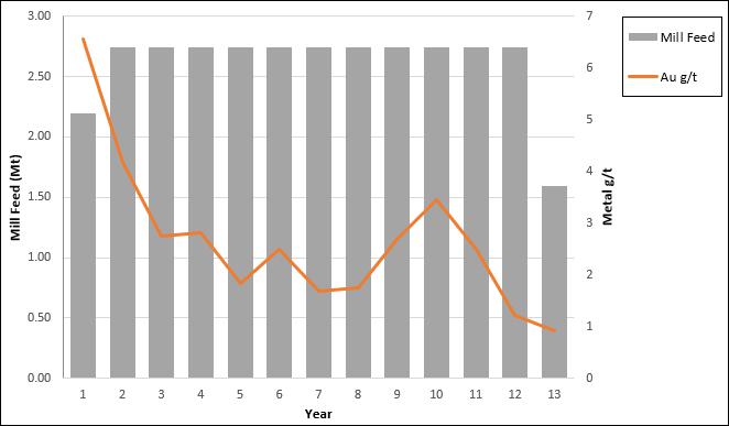
Source: MMTS,
2023
| Courageous Lake Project | Page 211 |
| Pre-feasibility Study and Preliminary Economic Assessment NI 43-101 Technical Report | January 5, 2024 |
The
process flowsheet for Courageous Lake project was selected based on the preliminary metallurgical testwork results and subsequent economic
modelling. The majority of the unit operations selected to build the plant flowsheet are standard technologies widely used in gold processing
plants. The POX circuit is technologically complex and requires skilled operators.
The
selected flowsheet includes a three-stage crushing circuit with crushed product reporting to the crushed material stockpile. Mineralized
material is reclaimed to a grinding circuit consisting of a ball mill circuit operating in closed circuit with a cyclone cluster. Ball
mill cyclone overflow reports to sequential stages of rougher flotation, where concentrate is separated from the gangue material and
fed to cleaner flotation. In the cleaning circuit, the concentrate grades are upgraded prior to further size reduction in a regrind ball
mill operating in closed circuit with a cyclone cluster. Cleaner tailings combine with rougher tailings for thickening before being discharged
to the CPSF. Overflow from regrind cyclones undergoes acidulation and thickening prior to POX which oxidizes the sulphide in the concentrate.
The oxidized concentrate is washed in a three-stage CCD to remove acidic solution prior to being leached with cyanide and washed in six-stage
CCD circuit to recovery the leached gold and silver in solution. The resulting pregnant solution will be processed using a Merrill-Crowe
treatment by adding zinc powder to precipitate gold and silver. The precious metals precipitate will be smelted on site to produce gold-silver
doré bars. Leach residue is neutralized with rougher tails and lime addition and detoxed with the SO2/Air processes before pumping
to the leach residue tailings facility (LRTF).
Key
considerations for selecting the process flowsheet included the variable mineralogy, feed grades and rock hardness in the deposit. Multiple
trade-off studies were conducted in order to select the optimal process flowsheet, including throughput sizing, comminution equipment
selection, POX method, and flotation circuit assessment. Capital and operating costs were minimized without compromising functionality
or robustness in the design.
Design
parameters (Table 17-1) were selected based on test data from programs SGS (2003), G&T (2007) and SGS (2011). The ALS (2023) test
program was run in parallel with the 2024 PFS, and upon completion the test results were evaluated against the selected design basis.
Results from the 2023 testwork confirmed the design parameters were sufficient but also identified opportunities for optimization that
have not been realized in this report but are included in Section 25.3.2.3.
The
overall process plant layout is depicted in Figure 17-2.
| Courageous Lake Project | Page 212 |
| Pre-feasibility Study and Preliminary Economic Assessment NI 43-101 Technical Report | January 5, 2024 |
| Table 17-1: | Summary
of Process Design Criteria |
| Parameter |
Units |
Value |
| Plant throughput |
Mt/a |
2.74 |
| Throughput, design |
t/d |
7,500 |
| Life of mine |
y |
12.6 |
| Gold head grade, design |
g/t |
5.65 |
| Sulfur head grade, design |
% |
0.48 |
| Silver head grade, design |
g/t |
0.8 |
| Iron head grade, design |
% |
2.3 |
| Arsenic head grade, design |
% |
0.3 |
| Calcium head grade, design |
% |
2.4 |
| Carbon head grade, design |
% |
0.7 |
| Material specific gravity |
- |
2.7 |
| Crushing plant availability |
% |
65 |
| Crushing plant capacity, design |
t/h |
481 |
| Crushing
circuit product size, P80 |
mm |
9 |
| Bond crusher work index (CWi), design |
kWh/t |
24 |
| Bond ball mill work index (BWi), design |
kWh/t |
16.5 |
| Bond rod mill work index (BWi), design |
kWh/t |
18.1 |
| Bond abrasion index (Ai), design |
- |
0.19 |
| Mill availability |
% |
90 |
| Oxidation circuit availability |
% |
90 |
| Grinding circuit capacity, design |
t/h |
348 |
| Grinding
circuit product size, P80 |
µm |
106 |
| Primary classification cyclones O/F pulp density, design |
%w/w |
35 |
| Primary grinding circuit configuration |
- |
closed |
| Rougher stage mass pull, max |
% |
11 |
| Concentrate pulp density |
%w/w |
25 |
| Concentrate solids specific gravity |
- |
3.05 |
| Cleaner mass pull of overall circuit, max |
% |
4.2 |
| Overall Au Recovery to Concentrate |
% |
88 |
| Overall Ag Recovery to Concentrate |
% |
85 |
| Regrind circuit configuration |
- |
closed |
| Regrind mill type |
- |
ball mill |
| Regrind circuit feed size, P80 |
µm |
90 |
| Regrind circuit product size, P80 |
µm |
43 |
| Regrind mill specific energy, design |
kWh/t |
9.2 |
| Courageous Lake Project | Page 213 |
| Pre-feasibility Study and Preliminary Economic Assessment NI 43-101 Technical Report | January 5, 2024 |
| Oxidation
Circuit Feed Specification, design |
| C (as CO3) |
% |
1 |
| As |
% |
3.2 |
| Fe |
% |
12 |
| S |
% |
9.7 |
| Au |
g/t |
98 |
| Concentrate pre-treatment circuit capacity, design |
t/h |
15 |
| Concentrate settling rate |
t/m2/h |
0.25 |
| Concentrate thickener U/F density |
%w/w |
50 |
| Pre-acidulation residence time |
h |
1 |
| Oxidation circuit configuration |
- |
POX |
| POX residence time, design |
min |
90 |
| Operating temperature |
°C |
200 |
| Design pressure |
kPag |
2,580 |
| Number of flash stages |
# |
1 |
| Flash operating pressure |
kPag |
14 |
| POX counter current decantation (CCD) settling rate |
t/m2/h |
0.15 |
| POX CCD wash stages |
# |
3 |
| POX solution neutralization residence time |
h |
1.3 |
| POX solution neutralization circuit target pH |
- |
8.5 |
| POX solids neutralization residence time |
h |
4 |
| POX solids neutralization circuit target pH |
- |
10.5 |
| Leach system |
- |
Cyanide Leaching |
| Leaching residence time |
h |
12 |
| Leach Circuit Extraction, Au |
% |
97 |
| Leach Circuit Extraction, Ag |
% |
69 |
| Metal recovery method |
- |
Merrill-Crowe |
| Merrill-Crowe CCD wash stages |
# |
6 |
| Merrill-Crowe CCD washing efficiency |
% |
95 |
| Cyanide destruction method |
- |
air
/SO2 |
| Cyanide destruction residence time |
h |
1.5 |
| Flotation tails thickener U/F density |
%w/w |
65 |
| Courageous Lake Project | Page 214 |
| Pre-feasibility Study and Preliminary Economic Assessment NI 43-101 Technical Report | January 5, 2024 |
An overall process flow diagram is presented in Figure 17-1.
| Figure 17-1: | Process
Flowsheet |
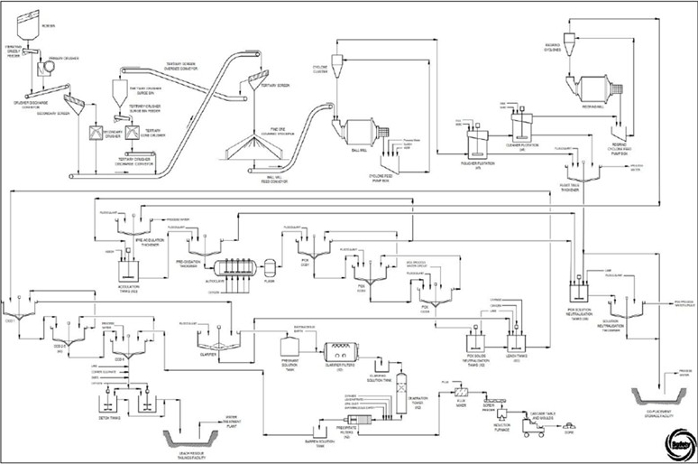
Source: Ausenco, 2023
| Courageous Lake Project | Page 215 |
| Pre-feasibility Study and Preliminary Economic Assessment NI 43-101 Technical Report | January 5, 2024 |
| Figure 17-2: | Overall Process Plant Layout |
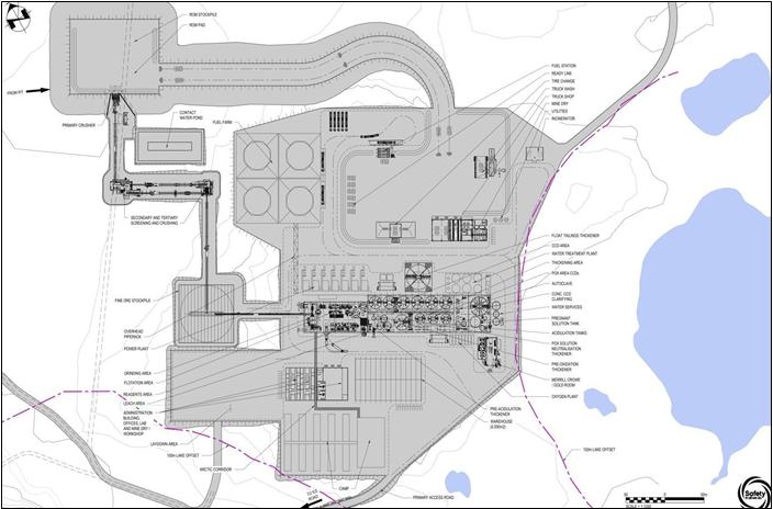
Source: Ausenco, 2023
| 17.3.1 | Crushing and Stockpiling |
Run-of-mine (ROM) material is hauled
from the mine and stockpiled or directly tipped into the ROM feed hopper. Material from the hopper is discharged by gravity to a vibrating
grizzly screen where oversize is discharged into the primary jaw crusher. This oversize material is crushed, a modular rock breaker is
included to manage large rocks that may exceed the crusher cavity size. The primary crusher is designed to reduce material size to an
80% passing product size (P80) of 94 mm. A magnet is installed to remove any foreign metallic bodies from the crushed material prior to
feeding it to the secondary screen. The primary crushing circuit has 60% operating availability and the design capacity of 481 t/h.
| Courageous Lake Project | Page 216 |
| Pre-feasibility Study and Preliminary Economic Assessment NI 43-101 Technical Report | January 5, 2024 |
Major equipment in this area includes
the following:
| · | vibrating grizzly feeder |
| · | primary jaw crusher (110 kW) |
| · | secondary screen feed conveyor. |
| 17.3.1.2 | Secondary and Tertiary Crushing |
The primary crusher discharge and
vibrating grizzly undersize is transferred to the secondary screen by the crusher discharge conveyor. The conveyor is equipped with a
belt magnet as well as a metal detector to remove any remaining metallic foreign bodies from the material. Screen oversize material is
gravity fed into the secondary cone crusher. Crusher discharge and secondary screen undersize is conveyed to the tertiary screen.
Both secondary and tertiary crushers
are located in the same building for optimal site layout and efficient performance of dust collection system. Tertiary crusher discharge
combined with secondary screen undersize material and secondary crusher product is transferred to the tertiary screen by the same conveyor.
Oversize from the tertiary screen is conveyed to the tertiary crusher surge bin which ensures the crusher is choke fed. Material that
passes through the tertiary screen discharges onto the fine ore transfer conveyor which will deliver material to the stockpile. The material
crushed by the tertiary crusher is reduced to an 80% passing product size (P80) of 9 mm at the screen undersize.
Major equipment in this area includes
the following:
| · | secondary screen (two decks) |
| · | secondary cone crusher (335 kW) |
| · | tertiary screen (two decks) |
| · | tertiary crusher surge bin |
| · | tertiary cone crusher (480 kW) |
| · | crusher discharge conveyor |
| · | fine material transfer conveyor |
| · | fine material stockpile (12 hour live capacity). |
| 17.3.2 | Primary Grinding and Classification |
Reclaim belt feeder transfers fine
material from the stockpile onto the ball mill feed conveyor which feeds the ball mill. The grinding circuit is designed for an annual
operating time of 7,884 h or 90% availability and a nominal throughput of 347 t/h. The circuit is sized
based on a grinding circuit feed size (F80) of 9 mm and a circuit product size (P80) of 106 µm. Process water is added to the ball
mill feed to maintain the mill discharge slurry density at 70% solids.
The ball mill product slurry will
discharge onto a rubber-lined trommel screen, and the oversize is screened out and discharged to a scats bin, whereas the trommel undersize
flows by gravity into the cyclone feed pumpbox, where the material is pumped to the cyclone cluster. Promoter and copper sulphate are
added to the cyclone feed pumpbox to activate gold-bearing sulphides for downstream flotation. Cyclone overflow at a nominal solids content
of 35% w/w reports to the flotation circuit.
| Courageous Lake Project | Page 217 |
| Pre-feasibility Study and Preliminary Economic Assessment NI 43-101 Technical Report | January 5, 2024 |
To feed the ball mill grinding media,
FELs feed balls from a storage bunker to charging kibbles. Each kibble opens into feed bins. Mobile feeders receive the grinding media
from the openings at the bottom of the ball feed bins and transfer the balls into the ball mill feed box.
Major equipment in this area includes
the following:
| · | primary cyclone cluster. |
The grinding, flotation, and concentrate
pre-acidulation circuits are depicted Figure 17-3.
| Figure 17-3: | Grinding, Flotation and Concentrate Pre-acidulation
Area Layout |
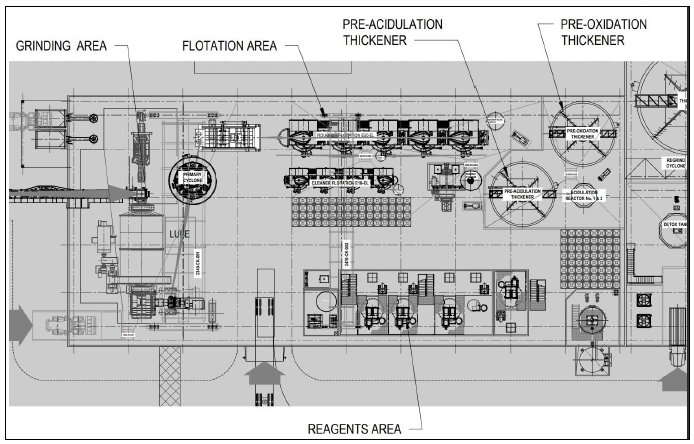
Source: Ausenco, 2023
| 17.3.3.1 | Rougher Flotation |
The overflow from the primary cyclone
reports to the rougher cell feed box. In this circuit, various reagents are employed to enhance the selectivity of the flotation process.
Flotation reagents used in the rougher circuit will include potassium amyl xanthate (PAX), copper sulphate (CuSO4), and methyl isobutyl
carbinol (MIBC).
| Courageous Lake Project | Page 218 |
| Pre-feasibility Study and Preliminary Economic Assessment NI 43-101 Technical Report | January 5, 2024 |
Process water is sprayed to launder
to maintain a pulp density of 25% w/w and low-pressure air is sparged into each cell to initiate bubble formation required for flotation.
The rougher concentrate is collected from each rougher cell and pumped to cleaner flotation, while rougher tailings flow into final tailings
pumpbox and combine with cleaner tailings. Combined flotation tailings will be thickened to 65% solids in the high-rate thickener. Portion
of the flotation thickener underflow will be used for neutralizing the acidic solution generated from the POX process. The rest of the
underflow slurry will combine with POX Solution Neutralization Thickener underflow prior to being discharged to the CPSF.
Major equipment in this area includes
the following:
| · | Five rougher flotation cells (58 m3 each). |
| · | Flotation tailings thickener. |
| 17.3.3.2 | Cleaner Flotation and Regrind |
The rougher flotation concentrate
will be further upgraded in cleaner flotation circuit. The first cell of the circuit is dosed with PAX and MIBC to promote concentrate
recovery. The cleaner concentrate at 25% w/w solids gravitates into concentrate pumpbox and is pumped to regrind cyclone cluster. The
regrind circuit consists of a cyclone cluster and a regrind ball mill operating in closed circuit. The overflow target product size is
43 µm. The cyclone overflow reports to the pre-acidulation thickener, while the underflow flows back to the regrind mill.
Major equipment in this area includes the following:
| · | Four cleaner flotation cells (12 m3
each). |
| · | Regrind ball mill (100 kW). |
| · | Regrind cyclone cluster. |
| 17.3.4 | Concentrate Acidulation |
Pre-acidulation thickener underflow
slurry, at 50% w/w solids, is pumped to two agitated acidulation tanks operating at 50°C. The concentrate will be contacted with a
portion of the acidic POX CCD overflow solution and fresh sulfuric acid solution. Sulfuric acid reacts with the carbonates to form gypsum
and carbon dioxide which reduces the generation of carbon dioxide in the autoclaves and thereby improves the utilization of oxygen. The
acidulated slurry is pumped to pre-oxidation thickener where it is thickened to 50% w/w solids prior to POX stage.
Major equipment in this area includes the following:
| · | Pre-acidulation thickener. |
| · | Pre-oxidation thickener. |
The autoclave vessel consists of
four compartments and five agitators and is operated at overall pressure of 2,150 kPa and 200°C. Oxygen is supplied via sparging system
at partial pressure of 690 kPa. The oxidation of sulphides in the slurry occurs autogenously once started and water is added to autoclave
as required to control the reaction temperature. The autoclave vessel is designed to provide residence time of 90 minutes. The oxidized
slurry and the vent gases discharge into a flash vessel where water is flashed to steam as the pressure is reduced to atmospheric. The
flash vessel is equipped with a gas scrubber to control steam and acidic emissions. The flash vessel slurry is sent to the POX CCD to
wash the acid out of the solids.
| Courageous Lake Project | Page 219 |
| Pre-feasibility Study and Preliminary Economic Assessment NI 43-101 Technical Report | January 5, 2024 |
Major equipment in this area includes the following:
| · | Horizontal autoclave vessel. |
| 17.3.6 | POX Counter Current Decantation (CCD) |
Oxidized slurry passes through a three-stage
CCD circuit, where gold containing solids are washed with process water to reduce slurry acidity. The washing ratio of the washing solution
to feed solids is 3:1. A portion of the acidic solution from the thickener overflow will be recycled to the pre-acidulation circuit, while
the rest of the solution from the POX CCD overflow will be sent to an acidic solution neutralization circuit. Solids are pumped to the
POX solids neutralization circuit.
Major equipment in this area includes three CCD thickeners.
| 17.3.7 | POX Acidic Solution Neutralization |
Remaining portion of the acidic wash
water from POX CCD circuit will be neutralized in 4 neutralization tanks with lime and a fraction of flotation tailings acting as neutralizing
agents. The neutralization tanks are sized to provide residence time of 80 minutes. The treated slurry with target pH of 8.5 will be thickened
to 35% w/w and pumped to flotation tailings pumpbox for discharge to the LRTF.
Major equipment in this area includes four tanks with agitators
and sparging system.
| 17.3.8 | POX Solids Neutralization |
The underflow of the third stage of
the CCD circuit will be pumped to an agitated tank where lime will be added to neutralize the slurry and increase the slurry pH to 10.5-11
prior to leaching stage. The neutralization tanks are sized to provide 4 hours of residence time at design flowrate.
Major equipment in this area includes two tanks with agitators
and air sparging system.
Neutralized slurry is pumped into
the agitated leaching tanks at 40% solids. Oxygen is sparged to each tank to maintain dissolved oxygen levels of 20 ppm. Hydrated lime
is added to maintain pH to the desired set point. Cyanide solution is added to the leach tank. The leach circuit consists of three agitated
tanks providing total residence time of 12 hours. The leached slurry from the last leaching tank will be washed using a CCD washing system
and the pregnant solution will be treated using a Merrill-Crowe process.
Major equipment in this area includes three leach tanks with
agitators and air sparging system.
| Courageous Lake Project | Page 220 |
| Pre-feasibility Study and Preliminary Economic Assessment NI 43-101 Technical Report | January 5, 2024 |
| 17.3.10 | Counter Current Decantation (CCD) |
A six stage CCD thickener washing
circuit will be used to recover soluble precious metals from the leach slurry. The underflow of the last CCD thickener will be pumped
to a cyanide destruction circuit prior to disposal. The overflow from the last CCD thickener will flow in a counter current mode to the
preceding thickener. The barren solution from the Merrill-Crowe circuit and fresh water will be used as a washing solution. The overflow
from the first CCD thickener to a clarifier reduced the total suspended solids prior to collection in the pregnant solution tank. The
pregnant solution tank was sized accordingly to store the pregnant solution prior to polish filtration stage. The washing ratio, washing
solution tonnage to feed solids tonnage, is 5:1 in order to achieve an overall CCD washing performance efficiency of higher than 99%.
Major equipment in this area includes the following:
| Figure 17-4: | Concentrate Acidulation, POX, and CCD |
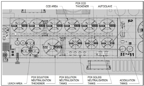
Source: Ausenco, 2023
| Courageous Lake Project | Page 221 |
| Pre-feasibility Study and Preliminary Economic Assessment NI 43-101 Technical Report | January 5, 2024 |
| 17.3.11 | Merrill-Crowe Precipitation Circuit |
The pregnant solution from the
CCD washing circuit will be treated using the Merrill-Crowe process to recover the contained precious metals by zinc-dust cementation.
The barren solution will then be reused in the CCD washing circuit as a washing solution.
The pregnant solution from the
first CCD thickener will be discharged to the pregnant solution tank. The pregnant solution will then be pumped to a leaf clarifier filter
pre-coated by a diatomaceous earth filter aid to remove suspended solids. The clarified solution will be pumped to the de-aeration tower
where the solution will be deoxygenated. The discharge from the de-aeration tower will be mixed with a slurry of zinc dust, lead nitrate,
and cyanide in the precipitate mixing tank where the precipitation reactions occur. The slurry with the gold and silver precipitates will
be pumped through a pre-coated filter press where the gold and silver precipitates, together with other solids, will be removed. The barren
solution will be reused as the washing water for the CCD washing circuit and as makeup water for cyanide leaching circuit and grinding
circuit.
The precipitation efficiency is estimated
to be higher than 99% for both the metals. A filter aid will be required for both the clarification filter and the precipitate filter
press. A small amount of lead nitrate will be also added to improve the precipitation efficiency.
Major equipment in this area includes
the following:
| · | Two clarification filters (one standby) |
| · | Two de-aeration towers (one standby) |
| · | zinc mixing and addition system |
| · | Two precipitation filters (two standby). |
| Courageous Lake Project | Page 222 |
| Pre-feasibility Study and Preliminary Economic Assessment NI 43-101 Technical Report | January 5, 2024 |
The Merril-Crowe and refining circuit
area is depicted Figure 17-5.
| Figure 17-5: | Merril-Crowe
and Refining Circuit Area Layout |
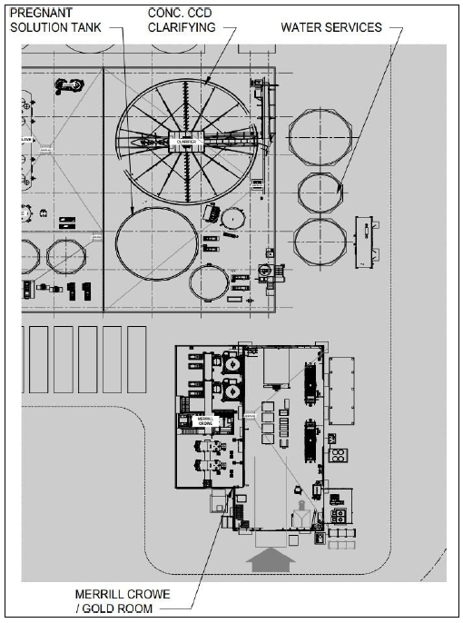
Source: Ausenco, 2023
| Courageous Lake Project | Page 223 |
| Pre-feasibility Study and Preliminary Economic Assessment NI 43-101 Technical Report | January 5, 2024 |
Gold and silver
precipitates from the Merrill-Crowe circuit will be further treated by smelting into gold-silver doré bars. The refining
process will be performed in a batch mode. The circuit will be in a secure enclosed area with CCTV cameras and restricted access.
Gold-silver doré products will be stored in a dedicated safe in the gold room.
Sufficient ventilation and off-gas handling
will be provided in the gold room for a healthy work environment. Fume and dust exposure for the melting furnace and material
handling will be controlled through a ventilation system installed in the gold room, including hoods, enclosures and wall fans to
follow the local regulations/guidelines.
| · | associated material handling and other systems (molds, dryers, scales, dust
collection system). |
| 17.3.13 | Cyanide Destruction and Neutralized Tailings Disposal |
Cyanide detoxification
will take place using the SO2/air process. In this process sodium metabisulphite will be used as the SO2 source,
copper sulphate is used as a catalyst and lime is used to maintain the pH of the reaction. The washed leach residue slurry from the CCD
washing circuit will be treated in the cyanide detoxification circuit consisting of two tanks in parallel that were sized for a total
residence time of 90 minutes. The cyanide destruction tanks are agitated and sparged with oxygen. This process will reduce the WAD cyanide
in the tailings to less than 25 mg/L before being discharged to the LRTF.
| 17.4 | Reagent Handling and Storage |
All the reagents that will be transported
to the site via the winter road during February and March each year. On-site storage will be provided for 12 months. Annual reagent consumption
rates are summarized in the Table 17-2.
Quicklime is received on site as
a coarse powder in bulk bags. The bags will be dropped into a bin with a bag splitter and metered to a slaking mill as required. The mixed
lime is placed in a storage tank with a 24-hour residence time and distributed to the process as required through distribution pumps operating
on a ring main.
Copper sulphate is received on
site as a dry powder in bulk bags. The bags are emptied into a mixing tank and mixed to produce a solution at 15% w/w concentration. The
mixed reagent is then transferred to a storage tank providing a residence time of 24 hours. The reagent is then dosed to the grinding
and detoxification circuits by dosing pumps.
PAX collector is delivered to site
as granulated solids in bulk bags. The bulk bags are lifted using a frame and hoist onto a bag-breaker at the top of an agitated mixing
tank. A dust collector removes any fine particulates that become airborne after emptying the bag. After opening the bag, the reagent is
mixed with raw water from distribution and transferred to a day-tank with a storage capacity
of 24 hours. The mixing tank is ventilated using a fan to remove any carbon disulphide gas. PAX is delivered to the flotation circuit
using multiple dosing pumps, one for each stage in the circuit.
| Courageous Lake Project | Page 224 |
| Pre-feasibility Study and Preliminary Economic Assessment NI 43-101 Technical Report | January 5, 2024 |
Aero 208 is delivered on site as
a liquid in 1,000 kg intermediate bulk containers (IBCs). Dosing pumps deliver the reagents without dilution to the required locations
within the flotation circuits.
MIBC frother is delivered to the
site as a liquid in 1000 L totes or intermediate bulk containers (IBCs). It is stored in a tank and used without dilution. Various dosing
pumps deliver it to the various flotation areas.
Flocculant is received on site
as a dry powder in bulk bags. The bags are lifted using a frame and hoist to a bag-breaker on top of a flocculant bin. A dust collector
removes fine particles and dust from the air from the opening of the bag. A screw feeder moves the flocculant to a heated hopper and a
blower moves the material into an agitated mixing tank. Raw water is used to mix with the flocculant to create a slurry. A flocculant
transfer pump moves the flocculant mixture into a storage day-tank with a capacity of 24 hours. Various dosing pumps supply each of the
thickeners with flocculant mixture. Prior to entering each thickener feed box, process water is used to mix with the slurry inside an
inline mixer.
Sodium cyanide is delivered to
site as powder in bulk bags. A bag splitter fitted with dust extraction will directly connect to the heated sodium cyanide mixing tank.
A dust collector removes fine particles and dust released in the area. A transfer pump moves the cyanide solution to a storage day-tank
with a capacity of 24 hours. Solution will be pumped to leach tanks. An HCN gas detector and alarm system is included in the sodium cyanide
reagent area to alert operators to the presence of toxic hydrogen cyanide gas. The sodium cyanide area is located adjacent or inside the
alkaline reagent area for easy access to alkaline pH modifiers.
| 17.4.8 | Sodium Metabisulphite |
Sodium metabisulphite (SMBS) is
used in the cyanide detoxification circuit. It is delivered to site as a powder in bulk bags. The bag is lifted into a bag splitter by
a frame and a hoist. A dust collector removes fine particles and dust from the air. The SMBS enters an agitated mixing tank with raw water
to dissolve the powder and create a solution. The reagent is supplied to the cyanide detoxification circuit by the dosing pump.
Sulfuric acid is used in the acidulation
circuit. It is delivered to site as liquid in intermediate bulk containers (IBCs). Sulfuric acid solution will be supplied to acidulation
tanks by dosing pumps.
| Courageous Lake Project | Page 225 |
| Pre-feasibility Study and Preliminary Economic Assessment NI 43-101 Technical Report | January 5, 2024 |
Zinc powder acts as a precipitation reagent. It is delivered
to site as powder in bulk bags and dosed to Merrill-Crowe circuit.
Lead Nitrate acts as a co-precipitation agent in Merrill-Crowe
circuit. It is received as powder in bulk bags, mixed to 20% strength; transferred to a storage tank and dosed to Merrill-Crowe circuit.
| 17.4.12 | Diatomaceous Earth |
Diatomaceous Earth is a pre-coat agent in the Merrill-Crowe
process. It is received as powder in bulk bags and dosed to pre-coat feed tank in the Merrill-Crowe circuit.
Oxygen required for POX in autoclave, leaching and cyanide
destruction will be generated on site in a vacuum swing adsorption plant.
| Table 17-2: | Reagents Consumption |
| Item |
Value
(t/a) |
| Diatomaceous Earth |
20 |
| Lime (quicklime) |
6,543 |
| Sodium Cyanide |
63 |
| Sulfuric Acid |
1 |
| Flocculant |
103 |
| MIBC |
29 |
| PAX |
65 |
| R208 |
20 |
| CuSO4 |
274 |
| Fluorspar |
5 |
| Borax |
9 |
| Silica |
5 |
| Nitre |
1 |
| SMBS |
640 |
| Zinc Dust |
14 |
| Lead Nitrate |
3 |
| Grinding Media |
2,466 |
| Diesel Engine Oil (15W-40) |
1,299 |
| Courageous Lake Project | Page 226 |
| Pre-feasibility Study and Preliminary Economic Assessment NI 43-101 Technical Report | January 5, 2024 |
Process water is recovered from CPSF
into the process water tank with live capacity of one hour. Process water is distributed around the plant from the process water tank.
The POX circuit has a dedicated water circuit which is used for POX CCD wash water. Makeup water required for the process water circuits
is 207 m3/h. This will be sourced from a combination of tailings return water, water treatment plant product, and raw water.
Raw water will be pumped from the
Courageous Lake into the raw water tank with a live capacity of 12 hours. Raw water is distributed by pumps for various application points,
including reagent preparation, gland seal, autoclave cooling and general mill makeup water supply. Plant raw water demand is estimated
to be 40 m3/h.
Potable water is produced by an on-site
potable water plant which processes water from the raw water tank and makes it fit for consumption and human use. Potable water is stored
in a tank with live capacity of 48 hours and for distribution across the processing plant.
The total installed power for the
process plant and estimated power consumption is given in Table 17-3. Further discussion on the operating costs and power consumption
for each area of the process plant is given in Section 18. The total estimated power requirement for the process plant is 96,760 MWh/a.
| Table 17-3: | Process
Plant Power Requirements |
| Area |
Installed
Power
(kW) |
Operating
Load
(kW) |
Operating
Power
(MWh/a) |
| Crushing and reclaim |
1,643 |
1,242 |
7,072 |
| Grinding and classification |
6,920 |
6,380 |
53,096 |
| Flotation and regrind |
649 |
528 |
4,394 |
| POX circuit |
1,237 |
927 |
7,719 |
| Leaching and Merrill-Crowe |
510 |
297 |
2,468 |
| Cyanide detox and tailings pump |
497 |
421 |
3,504 |
| Reagent and utilities systems |
3,105 |
2,139 |
17,800 |
| Tailings Disposal |
101 |
84 |
702 |
| Total |
14,662 |
12,020 |
96,760 |
| Courageous Lake Project | Page 227 |
| Pre-feasibility Study and Preliminary Economic Assessment NI 43-101 Technical Report | January 5, 2024 |
This greenfield project site will include the following facilities:
| · | Mining facilities, including
the mine office and dry, truck shop, tire change facility, truck wash, explosives storage and manufacturing facility, diesel fuel storage
and distribution, and ore stockpile. |
| · | Processing facilities,
including the primary, secondary and tertiary crushing, fine ore stockpile and reclaim conveyors, process plant, office and laboratory,
plant maintenance building. |
| · | Mine waste and water management
infrastructure, including waste and tailings storage facility, tailings distribution system, water reclaim system, downstream water management
ponds, and overburden stockpiles. |
| · | Mine water treatment plant, discharge pipeline and diffuser. |
| · | An aerodrome, plant site roads and haul roads. |
| · | General facilities, including
the camp, gatehouse, emergency response/ambulance bay, car wash, warehouse, reagent cold storage, administration building, communications,
emergency power diesel storage, raw, process and potable water storage and distribution, power plant, site sewage system, and solid waste
treatment. |
The locations of the site facilities were based on the following
criteria:
| · | Locate the facilities within the claim boundaries. |
| · | Leverage topographic advantages for all facilities to optimize construction
costs. |
| · | Locate waste rock storage facilities near the mine pits to reduce haul distance. |
| · | Locate the process plant,
and tailings storage facilities within a single catchment area with the mine to reduce the mine site footprint area. |
| · | Locate the process plant to take advantage of natural topography and avoid
watercourses. |
| · | Locate the primary crushing and ROM pad between the open pit and the process
plant to reduce hauling. |
| · | The tailings facilities location
was selected based on currently available technical and environmental criteria. Early engagement with local communities and Indigenous
Rightsholders is ongoing and will continue to inform tailings facility siting assessments. |
| Courageous Lake Project | Page 228 |
| Pre-feasibility Study and Preliminary Economic Assessment NI 43-101 Technical Report | January 5, 2024 |
The overall site layout is shown in Figure 18-1.
| Figure 18-1: | Courageous
Lake Project Layout Plan |
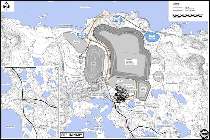
Source: Ausenco, 2023
Scrub brush clearing and topsoil removal are expected to
be required to allow construction of the processing plant and other buildings and facilities. Site civil work includes design for the
following infrastructure:
| · | Light vehicle and heavy equipment roads. |
| · | Ore and organic stockpiles. |
| · | Mine facility platforms and process facility platforms. |
| · | Water management ponds and ditches and channels. |
| · | Waste rock and tailings area. |
| Courageous Lake Project | Page 229 |
| Pre-feasibility Study and Preliminary Economic Assessment NI 43-101 Technical Report | January 5, 2024 |
| 18.3.1 | Courageous Lake Mine Spur Winter Road & Tibbitt to Contwoyto Winter Road |
The project site will be accessible
by the Courageous Lake Mine Spur Winter Road (CLWR), connecting to the Tibbitt to Contwoyto Winter Road (TCWR) that is normally open from
late January/early February until the end of March of each year. Table 18-1 shows historic TCWR opening and closing dates with open duration
and this data is further depicted in Figure 18-2.
Although access to the Project
is based on the operation of the TCWR winter access road, the Government of the Northwest Territories (GNWT) is currently engaged in evaluating
and preparing regulatory applications for the first segment of a potential all-season road (Slave Geological Province Corridor Project),
from Yellowknife to Lockhart Lake Winter Road Camp, that would replace the winter road. This potential all-season road segment, should
it be constructed, would improve access and reduce capital and operating costs for the Project.
| Table 18-1: | TCWR
Historic Opening and Closing Dates |
| |
Date |
Date |
|
|
Date |
Date |
|
| |
Open |
Close |
|
|
Open |
Close |
|
| 1983/84 |
17-Feb |
14-Apr |
56 |
2003/04 |
28-Jan |
31-Mar |
62 |
| 1984/85 |
30-Jan |
08-Apr |
68 |
2004/05 |
26-Jan |
05-Apr |
69 |
| 1985/86 |
22-Jan |
07-Apr |
75 |
2005/06 |
05-Feb |
26-Mar |
49 |
| 1986/87 |
14-Jan |
01-Apr |
77 |
2006/07 |
28-Jan |
08-Apr |
70 |
| 1987/88 |
N/A |
N/A |
- |
2007/08 |
28-Jan |
07-Apr |
69 |
| 1988/89 |
12-Feb |
09-Apr |
56 |
2008/09 |
01-Feb |
25-Mar |
52 |
| 1989/90 |
14-Feb |
07-Apr |
52 |
2009/10 |
04-Feb |
21-Mar |
45 |
| 1990/91 |
01-Feb |
22-Mar |
49 |
2010/11 |
28-Jan |
31-Mar |
62 |
| 1991/92 |
23-Jan |
13-Mar |
49 |
2011/12 |
01-Feb |
28-Mar |
56 |
| 1992/93 |
28-Jan |
22-Mar |
53 |
2012/13 |
30-Jan |
31-Mar |
60 |
| 1993/94 |
03-Feb |
01-Apr |
57 |
2013/14 |
30-Jan |
01-Apr |
61 |
| 1994/95 |
18-Jan |
03-Apr |
75 |
2014/15 |
30-Jan |
31-Mar |
60 |
| 1995/96 |
25-Jan |
13-Apr |
78 |
2015/16 |
09-Feb |
24-Mar |
44 |
| 1996/97 |
28-Jan |
12-Apr |
74 |
2016/17 |
01-Feb |
29-Mar |
56 |
| 1997/98 |
19-Jan |
04-Apr |
75 |
2017/18 |
30-Jan |
01-Apr |
61 |
| 1998/99 |
01-Feb |
30-Mar |
57 |
2018/19 |
30-Jan |
29-Mar |
58 |
| 1999/00 |
28-Jan |
03-Apr |
65 |
2019/20 |
31-Jan |
30-Mar |
59 |
| 2000/01 |
01-Feb |
13-Apr |
71 |
2020/21 |
08-Feb |
31-Mar |
51 |
| 2001/02 |
26-Jan |
16-Apr |
80 |
2021/22 |
N/A |
N/A |
- |
| 2002/03 |
01-Feb |
02-Apr |
60 |
2022/23 |
N/A |
N/A |
- |
Note: N/A = data not available
| Courageous Lake Project | Page 230 |
| Pre-feasibility Study and Preliminary Economic Assessment NI 43-101 Technical Report | January 5, 2024 |
The CLWR is accessed from the TCWR
and is estimated to be 26 km in length with 7 km on land (with small lakes interspersed) and 19 km on the larger Mackay Lake. From the
CLWR intersection to the TCWR it is 76 km to the Lockhart Lake maintenance camp. The Lockhart Lake maintenance camp is at station 170
km from the TCWR start at Tibbitt Lake.
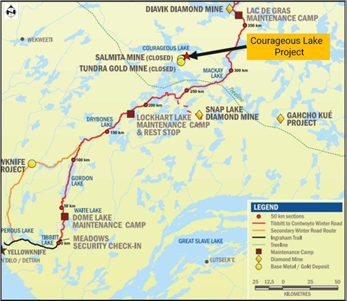
Source: Ausenco, 2023
| Courageous Lake Project | Page 231 |
| Pre-feasibility Study and Preliminary Economic Assessment NI 43-101 Technical Report | January 5, 2024 |
| Figure 18-3: | Courageous
Lake Project Winter Spur Road |
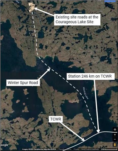
Source: Ausenco, 2023
The logistics plan for the Project
will depend on the maximum gross vehicle weight (GVW) allowed on the TCWR and on the spur road. From past projects on the TCWR a typical
maximum GVW of 77 t has been allowed. Loads above the standard ice road allowance in some cases will require that an engineering design
be prepared and submitted to the TCWR managers for the safe operation of the load on the TCWR. A 77 t GVW load would typically have a
tractor/trailer tare weight of 25 t and a payload of 52 t. When the GVW was more than 60 tonnes typically a tractor/trailer combination
of 9 to 10 axles was required.
| Courageous Lake Project | Page 232 |
| Pre-feasibility Study and Preliminary Economic Assessment NI 43-101 Technical Report | January 5, 2024 |
Using a 77 t GVW on a 9-axle bogie
and trailer layout, the required ice thickness is likely to be in the range of 102 to 109 cm. This ice thickness is for a travelling load,
not a parked load. This layout will likely require a Special Permit to travel on public roads. The exact required ice thickness can be
determined once the footprint details of the tractor/trailer combination are specified.
From TCWR operation reports for
the TCWR from 1997/1998 to 2022/2023 (25 most recent winter seasons) there were three winter seasons with difficult construction and load
hauling operations. In the 2005/2006 winter season full super B loads (which require 104 cm ice thickness on the TCWR) and other heavy
loads could not be transported on the TCWR (1 in 25 occurrence or 4%) due to a warm winter weather with lower freezing degree day (FDD)
values with resulting insufficient ice thickness. In the1998/1999 and 2009/2010 winter season warm winter season weather also hampered
the operation of the Super B trucks (2 in 25 occurrence or 8%). Total problem-year occurrence over this most recent 25-year period is
therefore 3 in 25 or 12 %.
For the TCWR with operation mostly
on lake ice the effects of global warming over the planned mine operation period are noted. From the same TCWR operation reports it was
noted that with the most recent construction methods that the 104 cm thickness for Super B train operation was being achieved at a Yellowknife
FDD of 2200 C-days as shown in the Yellowknife FDD Figure 18-4 by the blue graph line.
| Figure 18-4: | Yellowknife
FDD on March 31 and when Super B capacity of 63.5 tonnes (100%) at 104 cm on TCWR and FDD
where 109 cm expected |
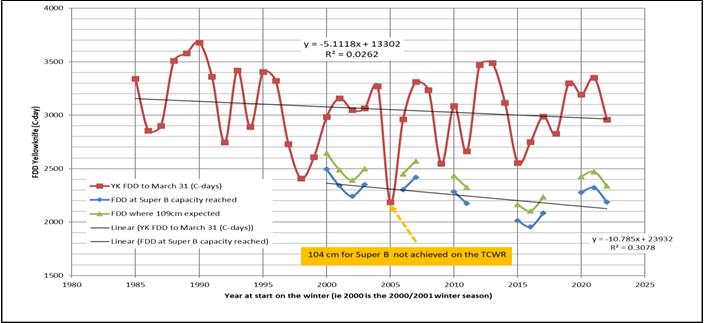
Source: Ausenco, 2023
| Courageous Lake Project | Page 233 |
| Pre-feasibility Study and Preliminary Economic Assessment NI 43-101 Technical Report | January 5, 2024 |
The Yellowknife FDD has decreased
by an average of 5.1 C-days/a from linear regression from the 1985/1986 to 2022/2023 winter season. This decreasing FDD trend is expected
to continue into the Project operation period and as a result the 12% TCWR operation problem- year occurrence will continue as a minimum
expectation. Figure 18-5 shows that the TCWR open duration is decreasing by 0.43 day/a by linear regression over the period 2003/2004
to 2020/2021.
| Figure 18-5: | TCWR
Historic Opening and Closing Dates with Open Duration |
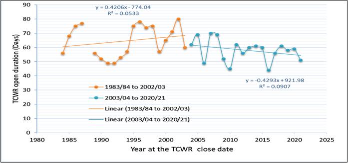
Source: Ausenco, 2023
| 18.3.1.1.1 | Proposed All-Season Road to the Lockhart Maintenance Camp |
The long-range plan for the Slave
Geologic region (north of Great Slave Lake) is in the early stages of planning a two lane all-season road into this region. The following
points highlight this plan:
| · | Two-lane gravel infrastructure corridor into the 213,000 km2 Slave
Geological Province. |
| · | Current focus: 179 km Lockhart All-Season Road. |
| · | The Government of the Northwest Territories
(GNWT) priority focus at the moment is to advance regulatory applications for the first segment of the corridor - the Lockhart All-Season
Road from Tibbitt Lake to Lockhart Lake. |
| · | $40 M has been secured for environmental planning
and engineering studies - $30 M is from Transport Canada’s National Trade Corridors Fund and the GNWT will fund the remaining $10 M. |
| Courageous Lake Project | Page 234 |
| Pre-feasibility Study and Preliminary Economic Assessment NI 43-101 Technical Report | January 5, 2024 |
On February 16, 2023, a workshop was held in Yellowknife
on development of access to the Slave Geological Province.
Even with the completion of this 179
km all-season road to Lockhart Lake camp there still is a further 76 km to the TCWR and CLWR intersection. This 76 km section is mostly
on lake ice on Lockhart Lake and MacKay Lake. Even with the all-season road to Lockhart Lake the truck loads to the Project will still
need to operate following an ice engineering design for safe operation.
The maximum winter GVW load is
71.3 t with the required number of axles. The NWT highways permit department likely would allow a 77 t GVW load on public highways with
required permit application.
Road access to Yellowknife from
Edmonton or Enterprise, the closest rail hub, is Highway 3 which passes over the Deh Cho bridge over the Mackenzie River. Review of a
design brief (EA-003 Deh Cho Bridge Corporation) for the bridge indicates a design live load of 750 kN or 76.5 t which is in line with
the suggested maximum load of 77 t GVW. In the first week of August 2023 one of the support cables on the bridge broke. After this cable
break a reduced speed limit and vehicle weight allowance was in effect until assessment and repair work was carried out.
| Figure 18-6: | Map
of Road Access to Yellowknife |
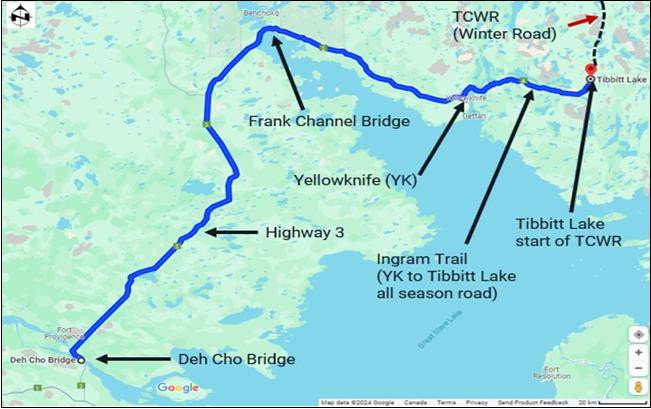
Source: Google Earth, 2023
| Courageous Lake Project | Page 235 |
| Pre-feasibility Study and Preliminary Economic Assessment NI 43-101 Technical Report | January 5, 2024 |
The aerodrome, located southeast
of the Project site, is published in the Canada Flight Supplement (CFS) as “Tundra Mine/Salmita Mine Aerodrome CTM7” (Aerodrome).
The aerodrome has runway (12T-30T) that is currently listed as 3,244 ft (989 m) in length. A site visit in 2010 however, indicated that
the runway has a useable length of approximately 4,396 ft (1,340 m), although the surface condition along the length has not been assessed
for the purpose of this Technical Report.
Runway length and width requirements for typical aircraft
operating at the aerodrome are provided in Table 18-2.
| Table 18-2: | Courageous Lake Aerodome Runway Length and Width
Requirements |
| Aircraft
Type |
Runway
Length Required |
Runway
Width Required |
| ATR-42 |
1,433 m (4,700 ft) |
30 m (100 ft) |
| Dash 8-300 |
1,494 m (4,900 ft) |
30 m (100 ft) |
| ATR-72 |
1,677 m (5,500 ft) |
30 m (100 ft) |
| Dash 8 Q-400 |
1,646 m (5,400 ft) |
45 m (150 ft)* |
| Avro RJ-85 |
1,768 m (5,800 ft) |
30 m (100 ft) |
Notes:
| 1. | 737-200 has not been included, with the likely retirement of the aircraft within the next few years. |
| 2. | The Dash 8 Q-400 has an Outside Main Gear Span wider than 9 m and therefore the standard states it requires a 45 m wide runway. |
| | DeHavilland’s operating manual allows operations on
a 30m wide runway. |
| 3. | The above runway lengths are calculated from Federal Aviation Administration (FAA)
information and aircraft manual data for Maximum Take-Off Weight (MTOW) at the aerodrome reference temperature and calm winds. Runway
lengths vary depending on aerodrome elevation, aircraft load (including fuel), ambient air temperature among other requirements. This
also includes air service provider safety requirements. Temperature, snow, ice, and prevailing wind direction are all variables that can
impact take-off and landing requirements. |
The distances in the above table are
likely conservative and should be re-evaluated by the air service provider prior to Feasibility Study and final design. The runway will
be designed to a length of 1,768 m (5,800 ft). Although the regulation allows a runway width of 30 m for most aircrafts, Tetra Tech recommends
a minimum runway width of 45 m for gravel surfaces due to more lateral movement of the aircraft on gravel/compacted snow surfaces and
fewer visual cues locating the runway centerline and touchdown zones in snow or compacted snow conditions.
A gravel runway is essentially a
flexible pavement, with a surface course of unbound granular material. Performance data based on a hard, smooth, and dry runway is usually
not valid when applied to a gravel runway.
The gravel pavement structure was
determined based on the Aircraft Load Ratings (ALR) and runway surface performance characteristics normally prescribed by the aircraft
manufacturers. Gravel runway strength is graded according to the California Bearing Ratio (CBR). The CBR is expressed in terms of the
percentage of the bearing capacity of a standard crushed limestone surface. As an example, a CBR of 15 means that the material in question
offers 15% of the resistance to penetration that the standard crushed stone offers. The underlying structure is designed to support the
surface material.
| Courageous Lake Project | Page 236 |
| Pre-feasibility Study and Preliminary Economic Assessment NI 43-101 Technical Report | January 5, 2024 |
Table 18-3 shows the ALR requirements
for the design aircraft type, and others for comparison.
| Table 18-3: | ALR Requirements for The Design Aircraft Type, and
Others for Comparison |
| Aircraft
Type |
Maximum
ALR |
| Avro RJ-85 |
7.9 |
| Dash 8 Q-400 |
6.4 |
| ATR-72 |
5.6 |
| ATR-42 |
4.9 |
| Dash 8-300 |
4.8 |
| Lockheed C-130 |
9.1 |
The gravel pavement structure thickness
is designed to prevent deterioration of the underlying permafrost while providing the required strength for the design aircraft.
The major airstrip design criteria are
as follows:
| · | Runway – The
design for the gravel surfaced runway provides for a 1,768 m (5,600 ft) long and 45 m (150 ft) wide runway. |
| · | Taxiway –
This design also includes a 23 m wide gravel surfaced taxiway, complete with 7.5 m wide graded shoulders, connecting to the apron. The
taxiway will include edge lighting and guidance signage. |
| · | Apron – The
gravel surfaced apron dimensions will allow for parking and maneuvering for two design aircrafts. Fuel spills and glycol overspray will
be collected in a lined sump off the edge of the apron and disposed of at a suitable location. |
| · | General –
The aerodrome will provide all-weather service and also includes the Air Terminal Building (ATB), Field Electrical Centre (FEC), and a
standby generator. Tetra Tech is proposing quarrying the material from the inferred bedrock at the southeast end of the runway (the suitability
of the quarry is yet to be confirmed by a geotechnical investigation). |
The site will not be stripped or
grubbed to provide the runway extension, taxiway, or apron. The total pavement structure for the extension areas will be a minimum of
2.0 m thick to protect the permafrost (there is already evidence of ice thaw in response to the removal of the overlying material in the
borrow areas surrounding the existing aerodrome). The pavement structure will be constructed primarily from quarried rock and gravel mine
waste, assuming a suitable quarry is developed.
The runway, taxiway, apron, and
ground vehicle parking areas will be top-surfaced with 300 mm of crushed granular base materials. Surface runoff should not be a concern
considering the runway is located on an esker (high ground) and is adjacent to Sandy Lake (south) and a low lying area and a lake (north,
northeast). Drainage “through” the embankment may be achieved at the runway extensions using a Permeable Embankment (PE) as
detailed in the EBA document “Guidelines for Development and Management of Transportation Infrastructure in Permafrost Regions”.
| Courageous Lake Project | Page 237 |
| Pre-feasibility Study and Preliminary Economic Assessment NI 43-101 Technical Report | January 5, 2024 |
Environmental diligence should be
taken during construction considering the proximity to the lake; mitigation assessments will likely be required. Silt fences and/or other
erosion deterrents will likely be required to mitigate contamination of site surroundings. Several active animal dens were noted during
Tetra Tech’s previous site visit.
It is recommended that a single
storey pre-fabricated ATB should be included to provide passenger/cargo shelter. The ATB may have an area for ground vehicle parking associated
with it. It has been assumed that potable water/sanitary sewer storage facilities will be included in the cost of the construction of
the ATB, and that the supply of water as well as removal of sanitary wastewater will be part of the mine camp operational routine.
Fuel facilities have not been included;
however, any fuelling of aircraft should be done in an area where a spill can be contained (the de-icing area). Refueling of aircraft
is not expected at the Courageous Lake Aerodrome and will likely occur in Yellowknife given the proximity.
Further investigation is required
for electrical power source; however, it is assumed for the PFS that a power generator equipped with battery bank backup power can be
provided to supply the power required at the aerodrome site. An FEC will also be included to house electrical infrastructure related to
the ATB and airfield lighting. This structure is typically a self-contained “sea-can” that comes with airfield lighting controls,
regulators, and switchgear.
The aerodrome lighting system that
is recommended to provide visual assistance to pilots operating aircraft to and from the airstrip during periods of darkness and low visibility
weather conditions consists of several elements. Light Emitting Diodes (LED) lighting for the edge lights, end lights, signage, and floodlights
have been included to significantly reduce power consumption and maintenance costs.
There are no navigational aids or
Instrument Approach Procedures (IAP) noted in the CFS or Canada Air Pilot (CAP) for the aerodrome at present. The aerodrome will require
development of Instrument Flight Procedures (IFP) by an IAP design specialist. New GPS procedures will allow the approach limits (Minimum
Descent Altitude or MDA) to be as low as 76.5 m (251 ft) above the airstrip elevation (i.e. the Above Aerodrome Elevation or AAE). These
are referred to as non-precision limits. The IAPs must be reviewed and approved by Nav Canada and Transport Canada prior to approval and
publication. The procedures require aircraft-based equipment only and do not require ground-based (on-airport) equipment other than the
provision of altimeter settings by the Automated Weather Observation Systems (AWOS) or ground personnel. IAPs for the Courageous Lake
aerodrome will be designed, approved, flight checked, and published in the future by a third party IAP designer. The process may take
as long as one to two years to complete.
The information related to construction
operations, routine airstrip operations, airstrip inspection, ground to air communications, aircraft services, airfield surface maintenance,
and emergency response services for the Project are detailed in the Tetra Tech report titled, “Courageous Lake Aerodrome PFS Update”
dated October 2023 (Tetra Tech, 2023).
The road connecting the existing airstrip
and the project site will be upgraded and on-site service roads will be constructed connecting to the wind power generation towers, ammonium
nitrate (AN) prill storage and explosive manufacturing facilities, tailing/residue storage facility, and open pit.
| Courageous Lake Project | Page 238 |
| Pre-feasibility Study and Preliminary Economic Assessment NI 43-101 Technical Report | January 5, 2024 |
The roads within the process plant
area will be integrated with process plant pad earthworks and designed with adequate drainage. The typical method of clearing, topsoil
removal, and excavation will be employed, incorporating drains, safety bunds and backfilling with granular material and aggregates for
road structure. The entrance to the process and mine site will be via the gatehouse.
The site will be accessible via
the main access winter road from late January/early February until the end of March. Access to the process plant and truck shop area is
controlled by a security gatehouse and perimeter fencing.
Gold-silver doré bars will leave
site by air in containers, for distribution to overseas markets.
| 18.4 | Electrical Power System |
| 18.4.1 | Electrical System Demand |
The estimated plant electrical
demand as used in the power supply estimates is as shown below, which is in accordance with the electrical load list (Ausenco, 2023) confirming
the annual GWh of energy consumption. The diesel powerplant equipment selection and consequent capital costs is for a minimum sized diesel
powerplant to supply a load as defined here:
| · | Annual plant energy consumption: 111 GWh. |
| · | Normal operating load: 13.6 MW. |
| · | Power factor: 0.87 lagging. |
The diesel powerplant equipment
selection and consequent capital costs is for a minimum sized diesel powerplant to supply a load as defined in the foregoing.
| 18.4.2 | Facility Power Supply |
The proposed diesel powerplant
will consist of seven modular diesel gensets, 1800 rpm, each nominal 3.1 MW continuously rated (ancillary loads allowed for), 3 phase,
60 Hz, 13.8 kV, 0.8 PF leading, with water jacket and exhaust gas heat recovery, with indoor day tanks and local control panels plus networking
and PLC automatic master control, with gensets mounted in double wide sound attenuated modules with fire detection, fire suppression and
horizontal and vertical (H&V) units for arctic conditions. Note, the 3.1 MW nominal capacity is the genset output after subtracting
related ancillary loads such as cooling fans.
The genset continuous ratings
will vary somewhat depending on the vendor, as these are standard products. The diesel powerplant is designed with n + 2 engines for
redundancy (allowing for one engine to be under overhaul and one down for service). This is the proven criteria for reciprocating
prime movers driving generators for a continuous mining operation.
| Courageous Lake Project | Page 239 |
| Pre-feasibility Study and Preliminary Economic Assessment NI 43-101 Technical Report | January 5, 2024 |
The power plant is designed to accommodate
a plant peak load of 16.1 MW, based on five gensets operating at the prime rating (110% of continuous). The layout design allows room
for an additional genset if required. Any further increase in the plant load or purchase of smaller gensets will require adding back the
eighth genset, which was removed when the load list (Ausenco, 2023) was revised. This will also require an updated layout drawing. Provision
will be made for the future installation of additional gensets, if required for any expanded operation.
The latest design considers moving
the power plant electrical room further away from the process plant (6m) to mitigate safety concerns with snowfall from the process plant
roof.
The modular powerplant will include
a double wide switchgear and control module including metal clad switchgear with 13.8 kV generator circuit breakers and circuit breakers
to feed the various plant loads. The switchgear will be split into two sections with a tie breaker and redundant station service and grounding
transformers such that any single fault will not cause a complete blackout.
Heat exchangers are included for
engine exhaust gas and water jacket waste heat, but the external loop circulating pumps, deaerators, and surge tanks are included in the
process plant, by others.
The required tank farm, diesel fuel
supply pumps, and piping are not part of the powerplant and are by others.
Refer to the below listed reference
reports, prepared by WN Brazier Associates Inc., for additional information on the power supply for the Project:
| · | Seabridge Gold Inc., Courageous Lake Project,
Modular Diesel Power Plant, 2024 PFS, Capital Cost Estimate. This report includes: |
| · | A summary of the plant equipment and installation costs. |
| · | A brief description of the diesel powerplant. |
| · | A spreadsheet detailed capital cost estimate. |
| · | A package of five conceptual powerplant drawings. |
| · | Excluded is the capital cost of emergency generators for the camp, mill and
other installations. |
| · | Excluded are the fuel tank farm and supply piping capital cost. |
| · | Seabridge Gold Inc. Courageous Lake Project,
2024 PFS, Diesel Generation, Power Cost Per Kilowatt Hour. This report provides: |
| · | The estimated per kilowatt hour cost of electric
power and also shows the total fuel consumption, based on the annual GWh of energy in accordance with the Ausenco Load List. |
| · | The calculated cost diesel power is C$0.44 per
kWh for fuel and O&M, not including amortization of plant capital cost. |
| Courageous Lake Project | Page 240 |
| Pre-feasibility Study and Preliminary Economic Assessment NI 43-101 Technical Report | January 5, 2024 |
| · | The power cost is based on a delivered No. 1
fuel oil (diesel) cost of C$1.54 per liter, as used for power generation. |
| · | Seabridge Gold Inc., Courageous Lake Project,
Report on Fuel Prices, For 2024 PFS. |
| · | This report estimates
the price of diesel fuel, delivered to site, including all freight and taxes, based on the three year trailing average of No. 1 diesel
fuel rack prices in Edmonton. Due to varying tax rates based on end use, several different costs per liter numbers are provided. |
| · | Courageous Lake 2024 PFS,
Diesel Power Generation & Distribution System, Design Criteria. This report provides information on: |
| · | Applicable codes and standards. |
| · | Site ambient conditions. |
| · | Diesel powerplant design criteria. |
| · | Tank farm requirements (conceptual design and
estimate by others). |
| · | Powerplant switchgear and ancillaries. |
| · | Power distribution design criteria, voltages,
cable standards, etc. |
| 18.4.3 | Site Power Reticulation |
Power will be distributed across
the site via 13.8 kV overhead lines originating from the plant’s 13.8 kV switchgear housed within the power plant electrical room.
Overhead distribution lines will
be constructed using aluminum conductor steel-reinforced cable (ACSR) and supported by wooden poles. The overhead powerlines will provide
power from the 13.8 kV switchgear to the collection pond pumphouse and explosive facilities.
| 18.4.4 | Plant Power Distribution |
The largest electrical loads at the
process plant are the ball mill and oxygen plant. The drive systems for both includes motors, feeder drives (FDRs), and bypass switchgear
to minimize voltage disturbances throughout the power distribution system during start-up. The ball mill and oxygen plant drive systems
will be supplied via cable circuits from the plant’s primary 13.8 kV switchgear. All other process and non-process plant loads will
be powered via 4160 V and V MCCs housed within electrical rooms strategically located throughout the plant area. Power will be stepped
down to 4.16kV, 600 V, and 120/208 V distribution, as required via grounded pad-mounted and pole-mounted transformers.
Power to the electrical rooms
will be supplied by resistance-grounded, secondary substation-type, dry-type distribution transformers located adjacent to the
respective electrical room. All electrical rooms will be adequately rated for the environment and outfitted with lighting and small
power transformers, distribution boards, uninterrupted power supply (UPS) systems, fire alarm and detection, and HVAC systems
designed for maintaining a positive pressure with respect to outdoor ambient pressure. To reduce installation time, the electrical
rooms will be pre-fabricated modular buildings installed on structural framework above ground level for bottom entry of cables.
Additionally, electrical rooms will be located as close as practical to the electrical loads to optimize conductor sizes and
minimize cable lengths.
| Courageous Lake Project | Page 241 |
| Pre-feasibility Study and Preliminary Economic Assessment NI 43-101 Technical Report | January 5, 2024 |
| 18.5 | On-Site Infrastructure |
| 18.5.1 | Process Infrastructure |
The processing plant will comprise several pre-engineered
and stick built buildings in addition to a fabric geodesic dome. Table 18-4 lists the buildings located within the main processing plant.
| Table 18-4: | Processing Infrastructure Buildings |
| Building/Area
Name |
Construction
Type |
Length
(m) |
Width
(m) |
Height
(m) |
Area
(m2) |
| Primary
Crushing |
Stick
Built |
19.5 |
7.0 |
14.2 |
137 |
| Secondary
Crushing and Screening |
Stick
Built |
28.0 |
11.0 |
18.5 |
308 |
| Tertiary
Crushing and Screening |
Stick
Built |
15.0 |
10.4 |
19.2 |
156 |
| Fine
Ore Stockpile Cover |
Fabric
Cover |
34 |
34 |
30 |
1,156 |
| Grinding
General |
Pre-Engineered |
32 |
35 |
30 |
1,120 |
| Rougher
Flotation Area |
Pre-Engineered |
48.0 |
35.0 |
23.0 |
1,680 |
| Merrill-Crowe
- Refinery |
Pre-Engineered |
36.2 |
33.9 |
7.0 |
1,227 |
The support buildings are listed in Table 18-5 below.
| Table
18-5: | General
Facilities |
| Building
Name |
Construction
Type |
Length
(m) |
Width
(m) |
Height
(m) |
Area
(m2) |
| Electrical
Rooms (two) |
Pre-Fabricated |
16.8 |
9.0 |
3.5 |
302 |
| Offices,
Administration Building and Laboratory |
Modular |
39.0 |
36.5 |
3.5 |
1,424 |
| Plant
Warehouse |
Pre-Engineered |
100.0 |
50.0 |
15.0 |
5,000 |
| Workshop |
Pre-Engineered |
39.0 |
39.0 |
15 |
1,521 |
| Incinerator |
Pre-Engineered |
17.5 |
12.5 |
5 |
219 |
| Explosive
Magazine |
Modular |
8.7 |
8.3 |
4.5 |
72 |
| Water
Treatment Building |
Stick
Built |
22 |
6 |
6 |
132 |
| Courageous Lake Project | Page 242 |
| Pre-feasibility Study and Preliminary Economic Assessment NI 43-101 Technical Report | January 5, 2024 |
A 204 bed permanent accommodation
camp will be located south of the process plant, connected via an arctic corridor. The camp will be installed at the beginning of construction
to house construction personnel and will then be maintained for operating staff.
The ROM stockpile will serve to
stockpile ore generated during pre-stripping from the initial operating years. Stockpiled ore will be reclaimed to supplement open pit
production maintaining the feed to the concentrator to full utilization. Any remaining material will be fed through the concentrator at
the end of mine life, meaning the operational ore stockpile will be completely removed upon project completion.
The fine ore stockpile will stockpile ore before the grinding
phase after going through the three crushing phases.
The on-site fuel storage will have
an 11 month capacity. The tank farms will be provided for fuel storage with an appropriate fueling station. The fuel storage reservoirs
will be contained within a bermed area and designed to meet applicable regulations. The fuel storage facility will have four tanks with
a total capacity of 60,000,000 L of diesel and will be located adjacent to the mine maintenance facilities.
There will be a single 100,000 L tank for gasoline storage.
| 18.5.6 | Overall On-Site Infrastructure |
The overall on-site infrastructure layout is shown in Figure
18-7.
| Courageous Lake Project | Page 243 |
| Pre-feasibility Study and Preliminary Economic Assessment NI 43-101 Technical Report | January 5, 2024 |
| Figure
18-7: | Overall
On-site Infrastructure Layout |
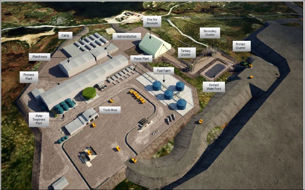
Source: Ausenco, 2023
| 18.6 | Mining Infrastructure |
Haul road widths are designed to
provide safe, efficient haulage, and to comply with the NWT Mines Regulations’ minimum width specifications and safe operating practice.
See Section 16.17.1 for a sample cross section of a haul road.
| 18.6.2 | Explosive Facilities |
The explosives manufacturing facility
and magazine storage facility will be supplied by the explosive vendor as part of the supply contract. The manufacturing facility will
be located 2 km to the southeast of the process plant and the magazine storage facility will be located 3.5 km south of the process plant.
See Section 16.20.4 for more details.
| Courageous Lake Project | Page 244 |
| Pre-feasibility Study and Preliminary Economic Assessment NI 43-101 Technical Report | January 5, 2024 |
An access road provides access
to the explosives manufacturing and storage facilities from the main site access road. Explosives and accessories will be transported
to the mine pits as needed.
| 18.6.3 | Truck Shop/Truck Wash |
The truck shop buildings will be
located just north of the process plant and will be used to maintain haul trucks and for spare parts storage. See Table 18-6 for a breakdown
of the truck shop buildings.
| Table
18-6: | Truck
Shop Facilities |
| Building
Name |
Construction
Type |
Length
(m) |
Width
(m) |
Height
(m) |
Area
(m2) |
| Truck Shop |
Pre-Engineered |
36.5 |
25.0 |
14.0 |
913 |
| Truck Wash |
Fabric Structure |
26.0 |
13.5 |
8.0 |
351 |
| Tire Change |
Stick Built |
17.0 |
16.0 |
8 |
272 |
| Mine Dry |
Modular |
32.8 |
25.0 |
3.5 |
820 |
The truck wash building at the site will be
in close proximity to the truck shop building on the truck pad, used for washing haul trucks, and supported on a reinforced concrete raft
foundation.
Figure 18-8 shows the truck shop, wash
bay, tire change/storage area, and fuel storage/station.
| 18.6.4 | Mine Warehousing, Office, and Workshops |
The truck shop warehouse to store
parts and mine maintenance will be located adjacent to the truck shop with a foundation of reinforced concrete slab on grade. The truck
shop office with lunchroom and washroom will be located adjacent to the mine dry building supported by a pre-cast concrete block foundation.
The tire change building will be used to store, maintain, and replace haul truck tires and supported by a reinforced concrete slab on
grade.
| Courageous Lake Project | Page 245 |
| Pre-feasibility Study and Preliminary Economic Assessment NI 43-101 Technical Report | January 5, 2024 |
| Figure
18-8: | Truck
Shop, Wash Bay, Mine Warehouse, Tire Change, Fuel Storage/Station and Office |
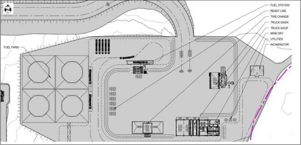
Source: Ausenco, 2023
| 18.7 | Co-placement Storage Facility and Leach Residue Tailings Facility |
Solids management consists of the
containment and long-term management of waste products developed during the LOM operations that consist of waste rock and tailings. Waste
rock will be generated during the mining of economical ore and will be directly hauled to the CPSF along with flotation tailings storage.
It is expected that the dumped, open graded rockfill (shot rock with average size of 24’’, or 600 mm) will have the porosity
greater than 40%. Stress levels within the waste rock portion of the CPSF will vary and will affect the effective stress of the rock fill.
High stress will reduce the effective stress of the rock fill. Tailings is a waste product of mineral exaction that consists of two tailings
streams: flotation tailings and neutralized leach residue tailings from POX circuit. The flotation tailings will be co-placed with waste
rock and the neutralized leach tailings will be placed in a separate facility.
Due to the specifics of site location
and freezing air temperatures from October to May, the thermal regime is expected to affect the deposition of tailings and decant water.
The effects of freezing and thawing of the tailings and water will need to be considered in further stages of the design process. The
thermal regime will not affect deposition of waste rock.
During the process of
developing the 2024 PFS, a new tailings deposition technology trade-off study was performed. The previous study considered a
neutralized leach residue tailings management facility (interior embankment slopes lined with geomembrane) and a flotation tailings
management facility (interior fully lined with geomembrane). Based on updated geochemistry, the neutralized tailings facility needs
to be fully lined and flotation tailings does not require a liner system. For flotation tailings, Ausenco, in conjunction, with MMTS
developed a CPSF strategy, which uses a paddock system for storing tailings in cells created by waste rock. A LRTF will be a fully
lined ring dike with downstream raises to contain the tailings. Both facilities are located east of the open pit.
| Courageous Lake Project | Page 246 |
| Pre-feasibility Study and Preliminary Economic Assessment NI 43-101 Technical Report | January 5, 2024 |
The key design criteria for the CPSF
and LRTF are as follows:
| 18.7.2.1 | Production Schedule |
The average flotation tailings
produced will be 7,241 t/d for a 12-year life-of-mine (LOM) of 29.7 Mt and the average neutralized leach residue tailings produced will
be 265 t/d for a total LOM of 1.1Mt (Refer to Table 18-7).
| Table
18-7: | Production
Schedule |
| Production
Year |
Flotation
Tailings (kt) |
Neutralized
Leach Residue Tailings (kt) |
Waste
Rock (kt) |
| -1 |
- |
- |
7,327 |
| 1 |
2,115 |
78 |
16,477 |
| 2 |
2,643 |
97 |
23,215 |
| 3 |
2,643 |
97 |
31,588 |
| 4 |
2,634 |
97 |
31,780 |
| 5 |
2,634 |
97 |
31,932 |
| 6 |
2,634 |
97 |
32,239 |
| 7 |
2,634 |
97 |
32,234 |
| 8 |
2,634 |
97 |
19,446 |
| 9 |
2,634 |
97 |
9,120 |
| 10 |
2,634 |
97 |
1,974 |
| 11 |
2,634 |
97 |
- |
| 12 |
1,146 |
42 |
- |
| Total |
29,691 |
1,089 |
268,115 |
| 18.7.2.2 | National and Local Waste Management Guidelines |
The CPSF and the LRTF will be designed in
accordance with Canadian Dam Association (CDA) “Application of Dam Safety Guidelines to Mining Dams” (2019) to provide a
safe and environmentally acceptable facilities for tailings and waste rock storage with a combined storage capacity of 298.9 Mt.
Both the CPSF and the LRTF have dam classification of ‘very high’, according to CDA guidelines due to the proximity to
the plant and open pit. Therefore, these facilities are designed to withstand the maximum credible earthquake (MCE) and probable
maximum flood (PMF).
| Courageous Lake Project | Page 247 |
| Pre-feasibility Study and Preliminary Economic Assessment NI 43-101 Technical Report | January 5, 2024 |
| 18.7.2.3 | Co-placement Management Facility (CPSF) |
The following parameters have been used
for the CPSF:
| · | Flotation tailings are non-acid generating (NAG) |
| · | Tailings slurry solids content is 60% |
| · | SG of the Solids is 2.75 |
| · | Particle distribution is 100% passing 300 µm, 50% passing 51 µm,
and 25% passing 18 µm |
| · | Settled dry density of tailings is 1.45 t/m3 |
| · | The nominal increase of
storage requirement for solids including entrained water is 5200 m3/d. The nominal daily release of decant water 2600 m3/d |
| · | In the period from October
to May the site is subject to the mean air temperature of -17.8°C and the volume solid storage requirements will increase at a rate
of 7800 m3/day (or 1.9 Mm3 for the period). The mean air temperature during the thawing period from June to September
is 9°C. During this period both the tailings and the frozen decant water will thaw and migrate into the interstitial space of the
waste rock along with 949,000 m3 of tailings (633,000 m3) and water (316,000 m3). No significant increase
of solid storage volume will occur. |
| · | Open graded shot rock with 24” (600 mm) mean diameter |
| · | Dry density of rock fill 1.65 t/m3 to 1.70 t/m3 |
| · | Direct haul from pit to CPSF |
| · | Spread and compact waste rock for paddock cell berms in 2 m lifts |
| · | Non-paddock cells waste rock spread and no compaction |
| · | Exterior paddock cells slopes 3:1 (H:V) |
| · | Interior paddock cells slopes 2:1 (H:V) |
| · | Paddock cell berm heights 14 m |
| Courageous Lake Project | Page 248 |
| Pre-feasibility Study and Preliminary Economic Assessment NI 43-101 Technical Report | January 5, 2024 |
| · | Operating water 0.5 m (max.), PMF 1 m, and freeboard 1 m |
| · | Paddock cell storage capacity 1.37 Mt (950,000
m3 - this does not include the volume within the pores of the pores of the waste rock). |
| · | The volume of the interstitial space within the
waste rock will start at 1.8 Mm3 at the end of Year1 and will have the rate of increase of 6.0 Mm3/annum, reaching
a maximum of 57 Mm3 by the Year 9. |
| · | Underdrain to capture (reclaim) decant water (free water) from tailings. |
| 18.7.2.4 | Leach Residue Tailings Facility |
Neutralized Tailings:
| · | The neutralized tailings are potential acid
generating (PAG) due to acidic sulphates (e.g. jarosite); short term leaching of sulphate, arsenic, CN-, and CN degradation products;
long term leaching of sulphate and arsenic. |
| · | Tailings slurry solids content is 30% |
| · | SG of the Solids is 2.75 |
| · | Particle distribution is 80% passing 22 µm, and 5% passing 5 µm |
| · | Consolidated dry density of tailings is 1.30 t/m3 |
| · | The nominal increase of storage requirement
for solids including entrained water is 203.8 m3/d. The nominal daily release of decant water 510.9 m3/d |
| · | Due to freezing temperatures for 9 months of
the year the solid storage requirement increases at the rate of 714.7 m3/d in the period
from October to May (195,649.1 m3 for the whole period) and 203.8 m3/d in the period from June to September (18,596.8
m3 for the whole period). The decant water storage requirement increases from zero for the period from October to May to 186,478.5
m3 for the period from June to September. |
LRTF Embankment:
| · | Waste rock shell direct haul spread and compacted
in 2 m lifts |
| · | Exterior embankment slopes 3:1 (H:V) |
| · | Interior embankment slopes 2:1 (H:V) |
| · | Interior liner system consists of 1.5 mm SST
LLDPE geomembrane, 1 m low permeability soil, 2 m filter zone |
| · | Operating water 1 m (max.), PMF 1 m, and freeboard
1 m. |
| Courageous Lake Project | Page 249 |
| Pre-feasibility Study and Preliminary Economic Assessment NI 43-101 Technical Report | January 5, 2024 |
| 18.7.3 | Geotechnical Investigation |
In 2010, SECON Private Limited
LLC completed a LiDAR survey, together with supporting aerial photography of the site and surrounding areas that confirmed the natural
topography of the site is very flat and offers very little in the way of geologic containment and management of large volumes of slurry
tailings or water.
Interpretation of the surficial geology
of the site was adapted from maps developed by Ward, et al. (1997) and enhanced using detailed aerial photo interpretation and ground
truthing. In addition, a geotechnical investigation of the site was undertaken by EBA during September 2010 (EBA, 2010d) and continued
during March 2011 with a winter drilling program (EBA, 2011a). A supplemental site investigation was carried out by EBA during March 2012
(EBA, 2012) to facilitate the design of Matthews Creek diversion channel, site infrastructure, and extension of the existing airstrip.
A total of six boreholes from the historical geotechnical programs were utilized in the development of the CPSF and LRTF. Additionally,
samples were taken as part of these programs, and a laboratory program was performed to determine geotechnical parameters of the overburden
(till) and underlying bedrock.
In the CPSF and LRTF area, surficial
unconsolidated material interspersed with patches of the exposed bedrock. Till dominates the project area terrain and consists predominantly
of unsorted sand and silt with variable proportions of gravel and traces of clay, with cobbles and boulders disseminated throughout. The
thickness of the till ranges from less than 1 m (a till veneer) to 6 m (ground moraine). The till is ice-rich, locally with some ground
ice bodies up to 1.3 m thick encountered in the upper 3 m.
The glaciofluvial deposits in the
project area form well-defined east-west trending esker ridges, mounds, and flanking aprons. The deposits consist of sand and silt, some
to trace gravel in planar, cross-stratified, and massive beds, with cobbles and boulders disseminated throughout.
Organic deposits, peat, and muck
up to 3. m thick occur as patterned peatlands in depressions and along creek valleys and drainage channel bottoms. They are ice-rich and
contain ground ice wedges, lenses, and layers of segregated ice that are manifested in peatland topography as ice-wedge polygons, thermokarst
collapse structures, and polygonal peat plateaus.
The underlying bedrock consists
of volcanic (felsic ash tuff of high to extremely high strength and excellent quality), meta-sedimentary rock with rock quality ranging
from very poor (in the uppermost portion with localized zones of frost-jacked blocks of rock protruding above the exposed bedrock surface)
to excellent, with rock strengths varying from medium (in the uppermost portion) to very high, and Precambrian granitic rocks. The granitic
rock is found in the western portion of the project area and has not been investigated during the shallow geotechnical drilling program.
Permafrost features include frost-crack
polygons, frost-jacked rock blocks and boulders, thermokarst features, non-sorted circles, patterned peatlands, and small frost mounds
in peatlands.
| Courageous Lake Project | Page 250 |
| Pre-feasibility Study and Preliminary Economic Assessment NI 43-101 Technical Report | January 5, 2024 |
| 18.7.4 | Co-placement Storage Facility |
The CPSF will store both
flotation tailings and waste rock in an unlined facility located east of the open pit (refer to Figure 18-1) to and ultimate
elevation of 500 masl (height of 79 m). Based on previous geotechnical investigations, the surficial geology below this facility is
underlain by 1 to 6 m of till overlying bedrock. Since the ratio of waste rock to flotation tailings generated during LOM ranges
between 8 and 11.5 (by mass) the waste rock will be used to generate paddock cells to store slurry tailings. Prior to process plant
operations, it will be necessary to construct a sufficient number of paddock cells to store tailings for the first two years of
operations. The paddock cells will be unlined, creating leaky embankments. During the freezing period, from October until May, the
tailings and decant water are expected to freeze up and create 1.9 Mm3 of solid volume. During the ‘warm’
season, which lasts from June to September, the solid mass is expected to thaw out and leak into the intertitial space along with
additional 632 700 m3 of fresh tailings and 316 300 m3 of decant water.
Seepage from the facility will
be captured in a constructed underdrain that conveys seepage to small lined ponds located around the footprint of this facility. Water
can be pumped from these ponds or allowed to discharge into the larger collection ponds or the pit and recovered for process operations
or treated and discharged to the environment. The starter CPSF is located 60 m to 90 m east of the open pit. The permanent internal perimeter
requires the removal of 0.3 m topsoil and 0.5 m overburden in a 150 m wide strip. The topsoil and overburden in the remainder of the footprint
will not be removed.
| Figure
18-9: | Co-placement
Storage Facility and Leach Residue Tailings Facility |
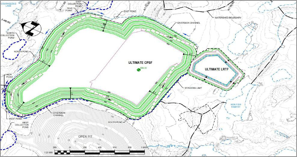
Source: Ausenco, 2023
The starter CPSF is located
west of a watershed boundary, so any runoff from this initial facility will drain into the open pit for the first two years of
operations (Refer to Figure 18-7). Each paddock cell will be designed to contain 1.37 Mt (950,000 m3) of flotation
tailings; therefore, the starter facility has been designed with four cells. Initially, an underdrain will be constructed by
excavating trenches and perforated pipe wrapped in a geotextile with drainage gravel, then 1 to 2 m of waste rock will be placed
over the terrain where the paddocks will be constructed. The underdrain is sized to capture seepage from tailings and precipitation.
The paddock cells have an exterior slope of 3:1 (H:V) and interior slopes of 2:1 (H:V). The berms are over 40 m wide at the crest to
account for lateral seepage from the cells and ensure seepage from the cell migrates to the underdrain system. Mine operations will
deliver the waste rock and dozers and compactors will spread and compact waste rock in the construction of the paddock berms. During
operations, tailings will be spigotted into multiple cells to allow seepage to migrate into the waste rock since there is no decant
collection system within the cells.
| Courageous Lake Project | Page 251 |
| Pre-feasibility Study and Preliminary Economic Assessment NI 43-101 Technical Report | January 5, 2024 |
The CPSF will be continuously constructed
and reclaimed over the life of the project along with the extension of the underdrain, even during winter months, due to the delivery
of waste rock from the open pit. Based on the LOM production schedule there is sufficient waste rock to build paddock cells and stay ahead
of flotation tailings disposal. The CPSF will be progressively closure during operations when an external lift is completed. Once a series
of paddock cells within a lift are completed, they will be covered with 10 m of waste rock prior to building the next lift of new paddock
cells above the closed cells. Again, tailings will be spigotted in multiple cells during operations over the life of the project to ensure
free water seeps into the waste rock and capture by the underdrain system. During the winter months it is assumed that 15 to 20% of the
free water will be lost due to ice entrainment. The ultimate CPSF occupies and area of 228 ha.
| 18.7.5 | Leach Residue Tailings Facility |
Due to the flat terrain, a ring
dike impounding structure is required to contain the leach residue tailings. The LRTF has been located south of the southeast corner of
the CPSF and 300 m east of the process plant and occupies an ultimate footprint of 24.5 ha. Based on previous geotechnical investigations,
the surficial geology below this facility is underlain by one to two meters of till overlying bedrock. Prior to process plant operations,
it will be necessary to construct a starter embankment (Phase 1 LRTF) to an elevation of 444 masl (8 m high) to provide storage capacity
for the first two years of operations. Prior to constructing the facility, 0.3 m of topsoil and 0.5 m of overburden will be removed from
the starter footprint. The starter embankment will be constructed with waste rock and a geomembrane liner, 1 m of lower permeability soil,
and 2 m filter zone will be installed on the interior slopes of the embankment. The liner system will continue throughout the base of
this facility with a prepared subgrade and geomembrane. The construction materials for the starter embankment will be sourced from the
pre-mining open pit excavation.
The LOM leach residue tailing generated is
only 1.1 Mt (m3 for solids storage), which is less than 4% of the total tailing stream from the process plant. During
Phase 1, the leach residue will be spigotted along the west and south sides pushing the supernatant pond to the northeast corner
where a floating barge will reclaim free water. During above zero temperatures, tailings can be spigotted from multiple points - the
fresh decant water will be added to the thawed one. However, during below freezing temperatures only a single point discharge will
be performed to ensure the development of a beach and not a buildup of tailings around the spigot due to freezing. Once this beach
has reached its design elevation, the spigot points will be moved to other locations to maximize the storage capacity of the
facility. During the winter months it is assume that 15 to 20% of the free water will be lost due to ice entrainment – the
volume of frozen tailings and decant water will be m3. Phase 1 can accommodate 175,000 t dry weight of leach residue over
a two-year period with an average dry density of 1.3 t/m3 after consolidation. For all phases, the facility has been
designed for a maximum of 2 m operating pond, containment of the PMF, and 2 m freeboard. The facility has not been designed with a
spillway.
| Courageous Lake Project | Page 252 |
| Pre-feasibility Study and Preliminary Economic Assessment NI 43-101 Technical Report | January 5, 2024 |
Phase 2 will be constructed during
the summer in Year 2 of operations and is downstream construction method to a crest elevation of 446 masl. The Phase 2 will provide 201,000
t of additional storage capacity. Phase 3 will raise the crest to an elevation of masl. Phase 3 will provide 300,000 t of additional storage
capacity. The ultimate phase will raise the crest to a final elevation of 449 masl (an ultimate height of 13 m), which will give a final
storage capacity of 1.1 Mt.
| 18.7.6 | CPSF and LRTF Stability Analysis |
Stability analyses were carried
out on critical sections of the planned ultimate CPSF and LRTF using both static and pseudo-static analyses. Based on similar projects,
for the CPSF and LRTF the estimated maximum credible earthquake for the area is 0.118 g for Type B soil and 0.158 g for Type C soils.
The Bray and Travasarou (2007) pseudostatic slope stability was used to verify performance of facilities during a design earthquake input
ground motion. The spectral acceleration at a degraded period of the potential sliding mass (Sa (1.5Ts)) was used as the optimal ground
motion intensity measure while the system’s seismic resistance was captured by its yield coefficient (ky).
Minimum factor of safety (FoS)
loading conditions minimum FoS required end of construction 1.3 Long-Term 1.5 Pseudo-Static 1.0 Post-Earthquake 1.2 (CDA, 2019) Limit
equilibrium analysis was conducted using peak effective strength soil parameters taken from the laboratory triaxial tests. The analysis
results for the CPSF and LRTF at their ultimate configurations indicate satisfactory FoS under static, pseudo-static, and post-seismic
conditions.
| 18.7.7 | CPSF and LRTF Water Management |
The CPSF and LRFF water management
systems include structures for surface water and seepage management. The surface water management will include three components:
| · | Contact water from the
CPSF and LRTF in open diversion channels that run on the surface along the toe of these facilities. |
| · | Seepage water in the foundations
of both facilities that will be captured using an underdrain system. The underdrain for the CPSF has been designed to capture decant water
(free water) from the tailings along with seepage from precipitation. |
The diversion channels will
collect non-contact surface runoff from the natural areas surrounding the facility and drain to drainage areas outside the CPSF and
LRTF footprint. The CPSF and LRTF surface water collection system was designed to collect surface contact runoff and direct the
water to the sediment ponds during operation; they will become non-contact water collection ditches after closure. The contact water
should only contain sediment from the facility and will be directed to sediment ponds and then pumped back to the process plant or
discharged to the environment. Water monitoring samples will be taken on a regular basis to ensure water being discharged meets
water quality standards. If the water does not meet standards, the water from the sediment ponds will be pumped to the filter plant,
then combined with the filtrate water and pumped to the process plant for water makeup or treated and discharged to the environment.
The temporary and permanent channel are designed to convey runoff from the 1-in-100-year and 1- in-200-year storm events,
respectively. The non-surface or drainage water management system will consist of HDPE dual wall pipe and drainage gravel wrapped in
a non-woven geotextile to capture near-surface groundwater and seepage from the tailings; capturing these water sources will
minimize build-up of the phreatic surface in the base of the tailings facility. In addition, the underdrain system will be utilized
to drain surface runoff that is blocked by the DSTF from following its original path. A ring-dyke filter system will be placed
around the underdrain inlet to prevent solids from entering and potentially plugging the system.
| Courageous Lake Project | Page 253 |
| Pre-feasibility Study and Preliminary Economic Assessment NI 43-101 Technical Report | January 5, 2024 |
| 18.7.8 | CPSF and LRTF Geotechnical Instrumentation |
The stability of the CPSF and LRTF
will be monitored by vibrating wire piezometers strategically placed within the base of these facilities. In addition, inclinometers and
prisms will be placed on temporary and permanent exterior slopes during operation. Real-time continuous and unattended monitoring will
be employed for the geotechnical monitoring. Additionally, water quality monitoring instrumentation will be implemented for monitoring
of seepage and contact water from these facilities in the small facility ponds located around these facilities that discharge into the
larger collection ponds.
| 18.7.9 | Closure and Reclamation |
The CPSF will provide long-term
storage of waste rock and flotation tailings and will remain in place beyond mine closure. For reclamation, the CPSF will be progressively
closed in stages following the completion of each outer permanent lift to maintain slope stability, minimize dust, minimize water infiltration,
and contaminant migration while being visually compatible with the surrounding area. The outer slopes of the waste rock will be graded
to flattened to 3:1 (H:V) as part of the operations to facilitate progressive closure. In addition, some flatter sloped caribou access
ramps will be constructed at designated locations. Contact water and seepage water from CPSF will be collected in the water collection
ponds and be pumped to during operations for process water utilization or treated, if required, and released to the environment and post
closure seepage and contact water will be pumped to the mined-out open pit until the water quality meets discharge criteria.
The overall LRTF closure design
strategy is to produce a walk-away closure condition with the facility decommissioned and reclaimed.
The primary closure objectives of the
LRTF closure are to:
| · | The LRTF cannot be progressively closed during operations due to the downstream
construction |
| · | provide a sound environmental closure design that
meets acceptable extractive industries best practice measures and minimizes environmental risks including re-establishment of a functioning
ecosystem and protecting air quality |
| · | preserve groundwater and surface water quality downstream of the LRTF |
| · | ensure the long term stability and integrity of the LRTF embankments |
| Courageous Lake Project | Page 254 |
| Pre-feasibility Study and Preliminary Economic Assessment NI 43-101 Technical Report | January 5, 2024 |
| · | integrate the LRTF into the surrounding landscape
and restore the natural appearance of the site to return the land to the pre-mining use and level of productivity. |
In order to help facilitate these
closure objectives, monitoring of geotechnical stability and environmental factors will be conducted until all governing parameters have
met acceptable closure criteria.
At the end of the LOM, reclamation
of the LRTF will commence. Any remaining free water will be pumped from the facility to the open pit at closure. The leached residue will
be capped with 2 m thick layer of waste rock to support a closure cover over the tailings with a 3% grade away from the center of support
potential settlement of the cap and provide positive drainage off the top of the facility. A geomembrane with protective layers above
and below will be placed over the top to prevent seepage into the lined facility. Then the waste rock shell will be overlaid by a 2 m
cap of overburden and 0.3 m cover of topsoil along with a vegetative cover to minimize seepage and ingress of air into the waste rock
shell. During post-closure, the contact water from the LRTF will be pumped to the open pit until the quality of the contact water meets
discharge criteria.
During operations portions of the
leach residue will freeze and create potential ice lens during operations. Post closure, depending on the time of the year the upper portion
of the tailings will be frozen or will freeze during post-closure. In the next phase, long term thermal modeling of the tailings will
look at the depth of freezing of the tailings.
| 18.8 | Groundwater Management |
The site is located within the
zone of continuous permafrost. In areas of continuous permafrost there are generally two groundwater flow regimes: a deep groundwater
flow regime beneath permafrost and a shallow groundwater flow regime located in the active (seasonally thawed) layer near the ground surface.
Groundwater in the active layer flows to local depressions and ponds that drain to larger lakes. The deep groundwater generally flows
from higher-elevation lakes to lower-elevation lakes. This can be influenced by the permeability of the rock mass and/or structural features
such as the Tundra Shear Zone that may preferentially influence flow direction. Due to the thick, low permeability permafrost, there is
generally little to no hydraulic connection between the two flow systems.
In the Canadian Shield, concentrations
of total dissolved solids (TDS) in groundwater increase with depth. This is primarily due to upward diffusion of deep-seated brines. Two
Westbay wells were installed to sample the sub-permafrost groundwater for water quality assessment. The TDS from two sampling intervals
of the Westbay 2 well were in the range of 8215 to 9495 mg/L indicating the sub-permafrost groundwater to be highly saline.
The freezing point of water decreases
when pressure and salinity increase, and unfrozen groundwater can be encountered at temperatures less than 0°C. This occurs at the
transition from the permafrost to the sub-permafrost groundwater flow regime and is termed the basal cryopeg. Within this zone and within
the underlying sub-permafrost groundwater regime, groundwater inflows to the pit and high groundwater pressures behind the pit walls and
below the pit floor can develop. The thickness of the basal cryopeg has been estimated in a range of 25 to 50 m. A depth of 310 m bgs
has been used as a Base Case assumption for the top of the basal cryopeg as input into the groundwater model for the project. A sensitivity
analysis assuming the top of the basal cryopeg to be at 262 m bgs was also considered for estimating potential water quantity and quality
inflows to the pit.
| Courageous Lake Project | Page 255 |
| Pre-feasibility Study and Preliminary Economic Assessment NI 43-101 Technical Report | January 5, 2024 |
The conceptual permafrost conditions for the project
area and the PFS pit at the end of mine life is shown in Figure 18-10.
| Figure
18-10: | Conceptual
Permafrost Conditions for the Courageous Lake Project |
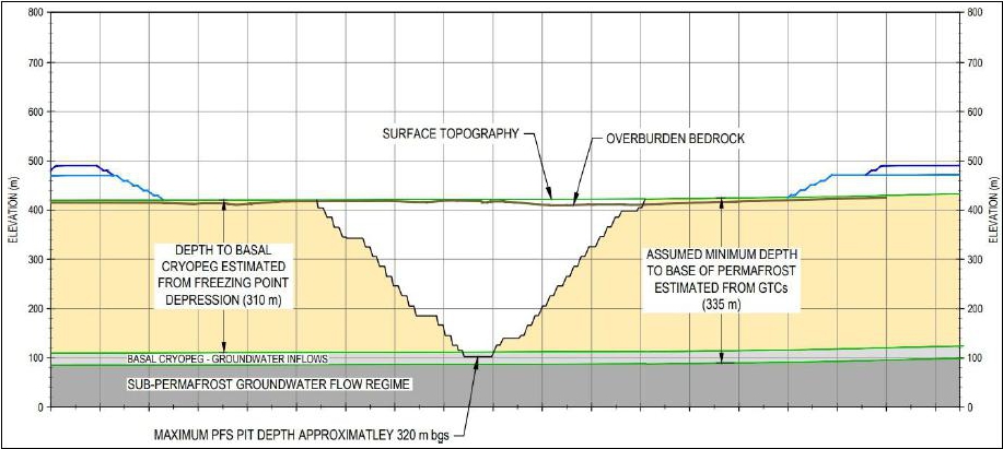
Source: Tetra Tech, 2023
Most of the pit slopes will be excavated
within permafrost. The base of permafrost is undulating, with an average depth estimate of 335 m below ground surface. It is assumed that
no groundwater pressures will be present within the portions of the pit walls excavated in the perennially frozen permafrost; however,
groundwater inflows to the pit may increase as the base of permafrost is approached through the basal cryopeg, beginning in Year 10 or
Year 11.
A 3-D groundwater model was developed
by WSP in 2011 using FEFLOW and updated in 2023 to FEFLOW Version 8. The model is a simplified representation of groundwater flow system
and has been used to predict groundwater inflow quantity to the pit and associated TDS concentrations. Transient model simulations were
prepared for the following two cryopeg scenarios:
| · | Base case scenario (top of Cryopeg assumed to be at 310 m bgs) with and without
depressurization. |
| · | Alternative scenario (top of Cryopeg assumed to be at 262 m bgs) with and
without depressurization. |
The PFS mine schedule indicates
the open pit will be excavated over 11 years, with construction beginning in Year -1. The pit floor will extend below the assumed top
of cryopeg for the Base Case beginning in Year 11 and increased groundwater inflows to the pit are expected. For the alternative scenario,
the pit floor will extend below the top of cryopeg in Year 10. The predicted groundwater inflows and water quality are presented in Table
18-8.
| Courageous Lake Project | Page 256 |
| Pre-feasibility Study and Preliminary Economic Assessment NI 43-101 Technical Report | January 5, 2024 |
| Table
18-8: | Predicted
Groundwater Inflow Quantity and TDS Quality – 2024 PFS Mine Plan |
| Cryopeg
Assumption |
Depressurization
Condition |
PFS
Mine
Year |
Predicted
Inflow to
Open Pit
(m3/d) |
Predicted
Inflow
to Wells
(m3/d) |
Predicted
Total
Inflow
(m3/d) |
Predicted
TDS
(mg/L) |
| Base Case – 310 m bgs |
Depressurization |
Year 11 |
600 |
2,150 |
2,750 |
7,400 |
| No Depressurization |
1,400 |
Not applicable |
1,400 |
7,400 |
| Alternative Scenario
– 262 m bgs |
Depressurization |
Year 10 |
1,350 |
3,100 |
4,450 |
6,600 |
| Year 11 |
950 |
2,500 |
3,450 |
10,050 |
| No Depressurization |
Year 10 |
2,800 |
Not applicable |
2,800 |
6,700 |
| Year 11 |
2,350 |
Not applicable |
2,350 |
9,800 |
Note: m3/d = cubic meters per day; mg/L = milligrams per
liter; m bgs = meters below ground surface
The predictions of groundwater inflow quantity and quality
do not include direct precipitation or runoff.
The preliminary design of a dewatering
system for the base case scenario consists of 14 wells around the circumference of the pit installed from an interior bench 50 m above
the top of the basal cryopeg. Each pumping well would be 100 m in length, installed to a depth of 50 m below the base of the PFS pit,
and with a spacing of 75 to 100 m around the circumference of the pit.
| Figure
18-11: | Preliminary
Concept of Dewatering Well Locations for Base Case and for Sensitivity Case Cryopeg Depth |
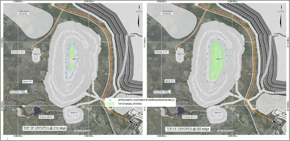
Source: Tetra Tech 2023
| Courageous Lake Project | Page 257 |
| Pre-feasibility Study and Preliminary Economic Assessment NI 43-101 Technical Report | January 5, 2024 |
The alternative scenario dewatering
system has the same general configuration but consists of 16 wells.
Submersible pumps and control systems
would be installed for each completed well, and pump houses and controls installed. It is understood that the water extracted by the wells
and also occurring as natural drainage to the base of the pit will be collected and pumped through heat-traced and insulated HDPE pipe
to surface containment areas (satellite pits) until mining of the pit is complete at which time the water will be returned to the base
of the pit.
| 18.9 | Site-Wide Water Management |
This section presents an overview
of site-wide management, encompassing the design of water management structures, hydrology considerations, and the site-wide water balance.
The review and interpretation of existing climate data, encompassing factors such as precipitation, snowfall, and evaporation, are crucial
for accurately estimating water balance and designing effective water management structures.
The site’s climate data is
based on the Matthews Creek meteorology station. Table 18-9 summarizes the data collected from 2007. The site experiences a wide temperature
range, with monthly average from -31.1°C to +18.2 °C, and an average daily mean temperature of -8.5°C. Wind speed is also
monitored at this site. The annual average wind speed is recorded at 4.4 m/s, with maximum gusts reaching up to 19.4 m/s. Precipitation
at the Project is relatively low. Most of the rainfall occurs during the summer months. The total annual precipitation between 2010 and
2011 averaged
199.1 mm with an average monthly precipitation
of 16.6 mm.
| |
Table 18-9: |
Summary of Matthews Creek Station Monthly Average Meteorological Observation |
| Month |
Air
temperature (°C) |
Precipitation
(mm) |
Relative
Humidity (%) |
Wind
(m/s) |
| Average |
Average
Maximum |
Average
Minimum |
Average
monthly total |
Average
Daily Mean |
Average
speed |
| Jan |
-27.6 |
-24.3 |
-31.4 |
5.9 |
77.0 |
3.6 |
| Feb |
-26.7 |
-22.3 |
-31.0 |
5.1 |
78.1 |
4.2 |
| Mar |
-23.9 |
-18.9 |
-28.8 |
6.5 |
78.0 |
4.7 |
| Apr |
-13.1 |
-8.0 |
-18.8 |
9.6 |
84.8 |
4.8 |
| May |
-4.1 |
0.5 |
-9.3 |
8.3 |
82.6 |
4.7 |
| Jun |
7.5 |
12.7 |
2.4 |
24.3 |
69.8 |
4.8 |
| Jul |
13.9 |
18.8 |
9.0 |
33.5 |
70.3 |
4.3 |
| Aug |
10.6 |
14.8 |
6.7 |
54.4 |
77.7 |
4.7 |
| Sep |
4.0 |
7.3 |
0.7 |
40.9 |
83.9 |
4.6 |
| Oct |
-4.5 |
-2.2 |
-7.3 |
7.7 |
88.2 |
5.1 |
| Nov |
-16.9 |
-12.9 |
-21.2 |
2.8 |
87.9 |
4.3 |
| Dec |
-26.1 |
-22.6 |
-30.1 |
3.2 |
78.7 |
3.9 |
| Annual |
-8.9 |
-4.8 |
-13.3 |
16.6 |
79.7 |
4.5 |
| Courageous Lake Project | Page 258 |
| Pre-feasibility Study and Preliminary Economic Assessment NI 43-101 Technical Report | January 5, 2024 |
| 18.9.2 | Water Management Structures |
The CPSF is at a topographic high.
For the site-wide water management, the site is divided into four drainage areas: North Catchment, West Catchment, East Catchment and
Open Pit. Runoff from each catchment will report to a collection pond via natural topography or excavated collection channels. Runoff
from the pit will report to the pit and be pumped to treatment or reused for process purposes. A non-contact diversion channel is proposed
along the East Catchment to divert non-contact runoff away from the facilities and to minimize the amount of contact runoff to be collected
and managed. The proposed water management structures for the Courageous Lake mine site are summarized below. An overview of the water
management strategy is illustrated in Figure 18-12.
| · | Diversion channels: diversion
channels are required to divert non-contact runoff away from the facilities and to minimize the amount of contact runoff to be collected
and managed. The design criterion for the diversion channels was the conveyance of 1:200-year peak flow without overflow. |
| · | Collection channels: collection
channels collect contact runoff from the CPSF, Process plant, and Camp area. The design criterion for collection channels was the conveyance
of 1:200-year peak flow without overflow. |
| · | Collection ponds: collection
ponds were proposed to store contact runoff from the collection channels. The collection ponds were sized to store a 1:200-year 24-hr
flood with a minimum freeboard of 0.5 m. The stored contact water will be treated or reused for process purposes. |
The mine planning strategy is to
keep waste rock within a single catchment for as long as possible; however, given the location of infrastructure, the collection ponds
would be required early in the construction phase. For this reason, a staged approach to the ponds was not considered at this stage and
it is envisioned that each pond would initially be constructed to its full size.
| Courageous Lake Project | Page 259 |
| Pre-feasibility Study and Preliminary Economic Assessment NI 43-101 Technical Report | January 5, 2024 |
| Figure
18-12: | Courageous
Lake Water Management Strategy |
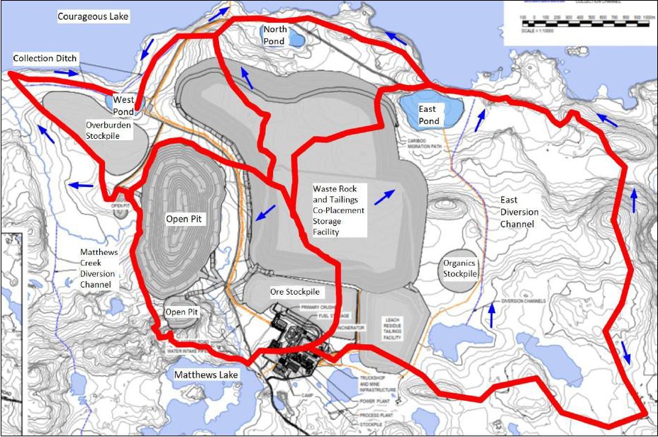
Source: Ausenco, 2023
An estimate of excavation volumes
was completed using the proposed geometries of the structures and elevation profile along the alignment of channels. As shown in Figure
18-1, the collection system is comprised of three collection channels, with a total length of 4,262 m. One diversion channel, with a length
of 2,767 m, was designed to divert the non-contact runoff approaching Courageous Lake project facilities.
To estimate design flows along
the water management system, flood from the design event was routed along the alignments using the rational method where the drainage
areas were small and had uniform soil and cover characteristics with no significant flood storage. The Rational Method is widely used
in determining peak runoff flows for small to medium sized catchments. The hydrologic modelling results were used to size the water management
structures of the Courageous Lake mine site preliminarily.
Channels were sized using estimated
peak flow rates and flood volumes from the rational method and frequency analysis results. Collection channels and the East diversion
channel were designed trapezoidal of 2:1 (H:V) side slopes with a minimum base width of 1 m and a depth ranging from 0.3 to 0.6 m. An
additional 0.3 m of freeboard was provided for all channels.
| Courageous Lake Project | Page 260 |
| Pre-feasibility Study and Preliminary Economic Assessment NI 43-101 Technical Report | January 5, 2024 |
The East Pond was designed with
a 5 m depth while the North and West ponds were designed with a 3 m depth. All three ponds have a 2:1 (H:V) side slope and freeboard of
0.5 m. To reduce the excavation required to construct the ponds, a berm along the north ends is proposed. At this stage, based on the
topography, it is envisioned that that these berms will be 3.3 m heigh and 5 m wide. East pond was sized using the contact water catchment
area in addition to the estimated 30% of non-contact water predicted to escape from the diversion channel. The dimensions and capacity
of the ponds are outlined in Table 18-10. A dam in the north end of the East Pond is also proposed to mitigate potential flow of contact
water further down the topography in that area.
| Table
18-10: | Dimension
of Collection Ponds |
| Item |
Length
(m) |
Width
(m) |
Capacity
(m3) |
| North Pond |
357 |
164 |
167,000 |
| East Pond |
575 |
256 |
546,000 |
| West Pond |
296 |
191 |
162,000 |
| 18.9.3 | Site-Wide Water Balance |
A water balance model was developed
to facilitate the design the water management structures. This model was created using GoldSim Software, with simulations running at daily
intervals. The simulations utilize monthly synthetics climate records for all modelled cases. The key facilities in the water balance
include the Main Pit, Satellite Pit, North Pond, East Pond, West Pond, and East Diversion. The water balance assessed three different
meteorological scenarios: average year, wet year, and dry year. Table 18-11 indicated the annual average precipitation for these different
scenarios.
| Table
18-11: | Hydrological
Scenarios |
| Hydrological
Scenarios |
Precipitation
(mm) |
| Wet (1/200 year) |
472 |
| Average |
337 |
| Dry (1/200 year) |
279 |
The water balance for three different
climate scenarios are shown in Table 18-12 through Table 18-14. As noted in Section 18.10.2, groundwater inflow to the open pit is expected
to be negligible for most of the operating life and were not considered in the Site-Wide Water Balance.
| Courageous Lake Project | Page 261 |
| Pre-feasibility Study and Preliminary Economic Assessment NI 43-101 Technical Report | January 5, 2024 |
| Table
18-12: | Site-wide
Water Balance (m3/day) for Average Precipitation Year |
Water
component
(m3/d) |
Jan |
Feb |
Mar |
Apr |
May |
Jun |
Jul |
Aug |
Sep |
Oct |
Nov |
Dec |
Mean
annual |
| Main Pit |
0 |
0 |
0 |
0 |
618.0 |
4471.0 |
1766.0 |
883.1 |
638.7 |
618.1 |
0 |
0 |
749.6 |
| Satellite Pit South |
0 |
0 |
0 |
0 |
46.6 |
337.0 |
133.1 |
66.6 |
48.1 |
46.6 |
0 |
0 |
56.5 |
| Satellite Pit North |
0 |
0 |
0 |
0 |
24.7 |
178.8 |
70.6 |
35.3 |
25.5 |
24.7 |
0 |
0 |
30.0 |
| North Pond |
0 |
0 |
0 |
0 |
530.3 |
3836.0 |
1515.0 |
757.5 |
548.0 |
530.3 |
0 |
0 |
643.1 |
| East Pond |
0 |
0 |
0 |
0 |
1672.0 |
12098.0 |
4779.0 |
2389.0 |
1728.0 |
1672.0 |
0 |
0 |
2,028.2 |
| West Pond |
0 |
0 |
0 |
0 |
536.7 |
3882.0 |
15833.0 |
766.7 |
554.6 |
536.7 |
0 |
0 |
650.8 |
| Table
18-13: | Site-wide
Water Balance (m3/day) for Wet Precipitation Year |
| Water
component |
Jan |
Feb |
Mar |
Apr |
May |
Jun |
Jul |
Aug |
Sep |
Oct |
Nov |
Dec |
Mean
annual |
| Main Pit |
0 |
0 |
0 |
0 |
724.5 |
5241.0 |
2070.0 |
1035.0 |
748.7 |
724.5 |
0 |
0 |
878.6 |
| Satellite Pit South |
0 |
0 |
0 |
0 |
54.6 |
395.0 |
156.0 |
78.0 |
56.4 |
54.6 |
0 |
0 |
66.2 |
| Satellite Pit North |
0 |
0 |
0 |
0 |
29.0 |
209.5 |
82.8 |
41.4 |
29.9 |
29.0 |
0 |
0 |
35.1 |
| North Pond |
0 |
0 |
0 |
0 |
742.4 |
5370.0 |
2121.0 |
1061.0 |
767.1 |
742.4 |
0 |
0 |
900.3 |
| East Pond |
0 |
0 |
0 |
0 |
2341.0 |
16937.0 |
6690.0 |
3345.0 |
2420.0 |
2341.0 |
0 |
0 |
2839.5 |
| West Pond |
0 |
0 |
0 |
0 |
751.4 |
5435.0 |
2147.0 |
1073.0 |
776.4 |
751.4 |
0 |
0 |
911.2 |
| Table
18-14: | Site-wide
Water Balance (m3/day) for Dry Precipitation Year |
| Water
component |
Jan |
Feb |
Mar |
Apr |
May |
Jun |
Jul |
Aug |
Sep |
Oct |
Nov |
Dec |
Mean
annual |
| Main Pit |
0 |
0 |
0 |
0 |
511.8 |
3702.0 |
1462.0 |
731.1 |
528.8 |
511.8 |
0 |
0 |
620.6 |
| Satellite Pit South |
0 |
0 |
0 |
0 |
38.6 |
279.0 |
110.2 |
55.1 |
39.9 |
38.6 |
0 |
0 |
46.8 |
| Satellite Pit North |
0 |
0 |
0 |
0 |
20.5 |
148.0 |
58.5 |
29.2 |
21.1 |
20.5 |
0 |
0 |
24.8 |
| North Pond |
0 |
0 |
0 |
0 |
439.0 |
3176.0 |
1254.0 |
627.2 |
453.6 |
439.0 |
0 |
0 |
532.4 |
| East Pond |
0 |
0 |
0 |
0 |
1385.0 |
10016.0 |
3956.0 |
1978.0 |
1431.0 |
1385.0 |
0 |
0 |
1679.3 |
| West Pond |
0 |
0 |
0 |
0 |
444.3 |
3214.0 |
1270.0 |
634.8 |
459.2 |
444.3 |
0 |
0 |
538.9 |
| Courageous Lake Project | Page 262 |
| Pre-feasibility Study and Preliminary Economic Assessment NI 43-101 Technical Report | January 5, 2024 |
| 18.10 | Contact Water Quality and Water Treatment |
| 18.10.1 | Contact Water Management |
As discussed in 18.9, the Project
is located north of Matthew Lake within subcatchments that drain north towards Courageous Lake as shown in Figure 18-12. Figure 18-13
shows the sub-catchments. Figure 18-14 illustrates the location of major mine components, including:
| ● | west satellite pit (available year -1) |
| ● | south satellite pit (available year 4) |
All mine contact water produced
within the project area is collected and pumped to the West Satellite Pit for temporary storage or to the water treatment plant (WTP).
Contact water is generally not suitable for use in the gold extraction process because of the sensitivity of the process to chloride.
Therefore, water for process must be supplied from Courageous Lake and most of the contact water will be treated and discharged. The water
treatment processes are described in Section 18.10.4.
The CPSF, for waste rock and flotation
tailings paddock storage, would be constructed within three subcatchments that drain north towards Courageous Lake. A fundamental design
basis for the mine waste management is to preserve Matthews Creek to the maximum extent possible; the open pit is the only disturbance
to Matthews Creek included in the project design. The northern portion of Mathews Creek is fully preserved and the diversion of Mathews
Creek is shown in Figure 18-2.
Runoff and seepage from the facility
are collected in ponds located northeast, north and northwest of the project area (East Pond, North Pond, and West Pond). Contact water
collected in the ponds is pumped to the West Satellite Pit for temporary storage or directly to the WTP. The tailings are placed in the
facility in paddocks with an underdrain collection system built into the paddocks. The underdrain system is directed to the contact water
ponds.
The LRTF, or POX residue facility,
is a lined pond where residuals from the POX process are permanently stored. Excess water (supernatant) would be pumped from the facility
to the WTP.
Water that collects in the open pit
is captured in a sump constructed at the bottom of the pit and pumped from there to the West Satellite Pit for temporary storage or directly
to the WTP. Figure 18-12 shows a water conveyance schematic that is the design for the contact water management system.
| Courageous Lake Project | Page 263 |
| Pre-feasibility Study and Preliminary Economic Assessment NI 43-101 Technical Report | January 5, 2024 |
Runoff and seepage from the ore stockpile
and from the mill complex area will be collected in local sumps and pumped or flow by gravity to the West Satellite Pit. The West Satellite
Pit will be allowed to fill with water naturally or may be used as reservoir for contingency storage of contact water.
The project includes one clean
water diversion channel (east diversion channel) that routes runoff from the eastern catchment north towards Courageous Lake.
The water treatment plant is located
within and adjacent to the mill building. Feed water for the plant is either pumped directly from contact water collection areas or from
the West Satellite Pit to a feed water equalization tank within the mill building. Treated water is pumped to a diffuser located in Courageous
Lake north of the Project area. Figure 18-15 shows a schematic of water conveyance for the Project.
| Figure 18-13: | Courageous Lake Project Area Sub-catchments |
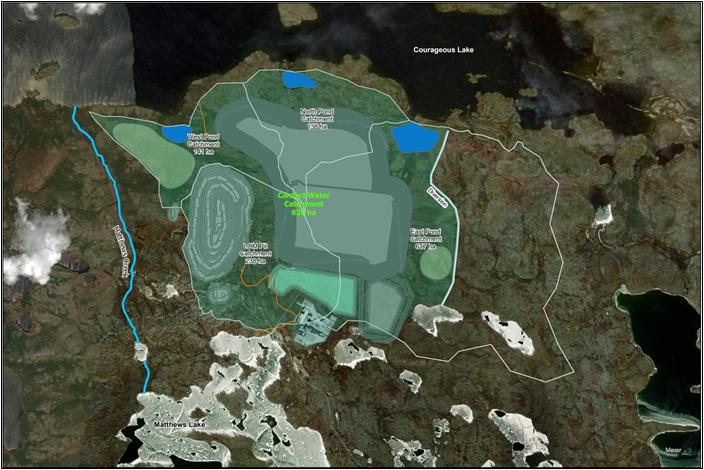
Source: SRK, 2023
| Courageous Lake Project | Page 264 |
| Pre-feasibility Study and Preliminary Economic Assessment NI 43-101 Technical Report | January 5, 2024 |
| Figure 18-14: | Water Management and Mine Infrastructure |
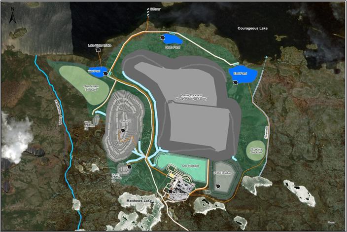
Source: SRK, 2023
| Courageous Lake Project | Page 265 |
| Pre-feasibility Study and Preliminary Economic Assessment NI 43-101 Technical Report | January 5, 2024 |
| Figure 18-15: | Water Conveyance Schematic |
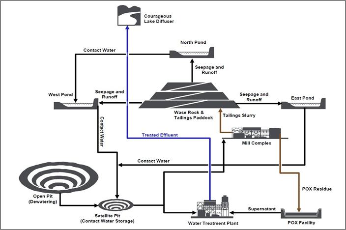
Source: SRK, 2023
| 18.10.2 | Contact Water Balance |
Elements of the water balance (Section
18.9.3) relevant to management of contact water and water treatment are summarized in this section.
Table 18-15 lists the assumed annual
average and 1-in-100 wet year precipitation and catchment yield for the project area. The annual volume of contact water collected site-wide
was estimated as the sum of annual yield from the contact water catchment (827 ha), losses from the clean water diversion to the contact
water catchment (50% loss was conservatively assumed), and groundwater reporting to the open pit.
| Courageous Lake Project | Page 266 |
| Pre-feasibility Study and Preliminary Economic Assessment NI 43-101 Technical Report | January 5, 2024 |
| Table 18-15: | Assumed Annual Precipitation and Catchment Yield |
| |
Total |
Unit |
| Average Annual Precipitation |
337 |
mm/a |
| 1 in 100 Wet Year Precipitation |
472 |
mm/a |
| Runoff Coefficient (Average Annual) |
0.65 |
- |
| Average Annual Catchment Yield |
219 |
mm/a |
| 1 in 100 Wet Year Catchment Yield |
307 |
mm/a |
In Years 1 through 10 of the operations
period, groundwater inflow to the open pit is expected to be negligible because mining will be within the confines of the continuous permafrost;
however, by Year 11, mining is expected to reach the basal cryopeg, which is the lowest section of permafrost where saline water with
a depressed freezing point flows. At that time, saline groundwater water will begin to report to the open pit.
Table 18-16 shows the estimated
annual volumes of contact water that would be collected in average and in 1 in 100 wet years. The annual demand for process make up water
is 1,330,000 m3/a for each of the 11 years of operation.
| Table 18-16: | Estimated Annual Contact Water Volumes Collected |
| |
Total |
Unit |
| Average Year, Ops. Years 1 to 10 |
2,100,000 |
m3/a |
| 1 in 100 Wet Year, Ops. Years 1 to 10 |
2,900,000 |
m3/a |
| Average Year, Ops. Year 11 |
3,100,000 |
m3/a |
| 1 in 100 Wet Year, Ops. Year 11 |
3,900,000 |
m3/a |
| 18.10.3 | Water Quality Assessment |
The assessment of contact water quality was
based on the geochemical source terms developed for the project. Geochemical source terms for the LRTF (POX residuals) supernatant, waste
rock seepage, ore stockpile seepage, and flotation tailings seepage, and runoff are summarized in Table 18-17.
| Table 18-17: | Geochemical Source Terms for POX Residues, Waste Rock,
and Tailings |
| Analyte |
Units |
POX
Residuals |
Waste Rock Seepage |
Ore seepage |
Flotation Tailings
Infiltration |
Flotation Tailings
Runoff |
|
|
Supernatant |
P50 |
P95 |
Expected Case |
Expected Case |
Expected Case |
| pH |
- |
8.8 |
Neutral |
Neutral |
Neutral |
Neutral |
Neutral |
| Sulphate,
SO4 |
mg/L |
880 |
420 |
960 |
1800 |
1800 |
3.1 |
| Cyanide |
mg/L |
16 |
n/a |
n/a |
n/a |
n/a |
n/a |
| Arsenic, As |
mg/L |
12 |
2.1 |
10 |
28 |
30 |
0.063 |
| Aluminum, Al |
mg/L |
0.01 |
0.076 |
0.076 |
0.076 |
0.076 |
0.061 |
| Courageous Lake Project | Page 267 |
| Pre-feasibility Study and Preliminary Economic Assessment NI 43-101 Technical Report | January 5, 2024 |
| Analyte |
Units |
POX
Residuals |
Waste Rock Seepage
|
Ore seepage
|
Flotation Tailings
Infiltration |
Flotation Tailings Runoff |
| |
|
Supernatant |
P50 |
P95 |
Expected Case |
Expected Case |
Expected
Case |
| Selenium, Se |
mg/L |
0.23 |
0.0058 |
0.015 |
0.0052 |
0.099 |
0.000027 |
| Cadmium, Cd |
mg/L |
<0.002 |
0.00072 |
0.0011 |
0.00063 |
0.014 |
0.0000039 |
| Lead, Pb |
mg/L |
<0.02 |
0.0004 |
0.0004 |
0.0004 |
0.0004 |
0.000052 |
| Chromium, Cr |
mg/L |
<0.1 |
0.011 |
0.015 |
0.014 |
0.36 |
0.000099 |
| Manganese, Mn |
mg/L |
0.51 |
0.23 |
0.23 |
0.23 |
0.23 |
0.018 |
| Iron, Fe |
mg/L |
0.01 |
0.063 |
0.063 |
0.063 |
0.063 |
0.0012 |
| Nickel, Ni |
mg/L |
<.05 |
0.012 |
0.058 |
0.01 |
0.24 |
0.000064 |
| Copper, Cu |
mg/L |
<.05 |
0.043 |
0.052 |
0.049 |
0.13 |
0.00069 |
| Zinc, Zn |
mg/L |
<.05 |
0.064 |
0.15 |
0.069 |
n/a |
0.00053 |
| Magnesium, Mg |
mg/L |
7.3 |
66 |
140 |
420 |
n/a |
2.7 |
| Sodium, Na |
mg/L |
47 |
19 |
23 |
58 |
n/a |
0.38 |
| Potassium, K |
mg/L |
2.5 |
66 |
91 |
460 |
n/a |
2.1 |
| Phosphorus, P |
mg/L |
<0.3 |
0.22 |
0.22 |
0.24 |
4.4 |
0.0012 |
| Mercury, Hg |
mg/L |
<0.0005 |
<0.00001 |
<0.00001 |
<0.00001 |
<0.00001 |
<0.00001 |
| Calcium, Ca |
mg/L |
420 |
730 |
840 |
1900 |
n/a |
12 |
| Antimony, Sb |
mg/L |
0.014 |
0.23 |
0.44 |
1.6 |
n/a |
0.0019 |
Waste rock, tailings, and ore stockpile seepage
are expected to account for the vast majority of loadings associated with mine contact water. Loadings from pit walls and general developed
mine areas such as roads, laydowns, mill and camp area are expected to be small in comparison.
A mass balance approach was used
for the water quality assessment. The POX facility, waste rock and tailings area and ore stockpile occupy half the contact water catchment
as depicted in Figure 18-13. Accordingly, contact water that flow from those areas is expected to have constituent concentrations comparable
to concentrations listed in Table 18-17. Therefore, the concentrations of the combined contact water collected would be a weighted average
of source term concentrations and runoff from undeveloped mine areas.
Constituents of potential concern
were identified by comparing source term concentrations to water quality guidelines and to concentrations that are typically deemed to
be acceptable in water licences in the NWT. The comparison was based on professional judgement rather than specific guideline concentrations
or permitted discharge limits. The assimilative capacity of Courageous Lake was considered in the same manner. Effluent from the site
was conservatively estimated to account for a maximum of 2.0% of the total flow in Courageous Lake at the proposed discharge location.
Concentrations that are of potential
environmental concern are highlighted in Table 18-17. These include arsenic and antimony in waste rock, ore stockpile and tailings contact
water and arsenic, cyanide and selenium in POX supernatant. A water treatment process that would remove these parameters from the contact
water is proposed prior to discharge of the water to Courageous Lake (see Section 18.10.4). Concentrations of other dissolved metals are
generally low.
| Courageous Lake Project | Page 268 |
| Pre-feasibility Study and Preliminary Economic Assessment NI 43-101 Technical Report | January 5, 2024 |
The project would also require management
of nitrogen nutrients (cyanide species, ammonia, nitrate and nitrate). Blasting of rock with ammonium nitrate fuel oil (ANFO) explosives
leaves undetonated residues that contain ammonia, nitrate and nitrite, which reports to mine contact water (open pit water, waste rock
and tailings seepage and runoff).
A more significant source of nitrogen
species is the cyanide used in the POX gold extraction process. Cyanide is used to leach gold released from the pressure oxidized ore.
Following gold extraction, the cyanide used in the process eventually reports to the neutralized POX tailings, which pass through a cyanide
destruction circuit. Here, cyanide is oxidized to various nitrogen species including nitrate, cyanate and thiocyanate. Combined, the residual
nitrogen species that report to waste rock and tailings seepage as well as supernatant from the POX facility is estimated to amount to
350 kg N/d, which corresponds to an annual average nitrogen concentration (all species) in the site contact water of 65 mg/L. Concentrations
of such magnitude exceed generally acceptable discharge limit. Therefore, the project requires a water treatment process for removal of
nitrogen.
800,000 m3 of saline
water with a total dissolved solids content of 7,400 mg/L is expected to begin flowing to the open pit in the last year of mining. Although
this water possibly could be collected and discharged to Courageous Lake, the plan for the PFS project is to store the water in the West
Satellite Pit until the end of mining at which time the water would be pumped back to the open pit. Because of the elevated salinity (and
higher density) the saline water would form a stable layer at the bottom of the pit lake that would endure in the post-closure period.
Closure of the open pit is discussed further in Section 20.1.2.1.3.
As discussed in Section 18.9.3,
water treatment for arsenic, antimony and nitrogen species will be required for the Project. The proposed treatment processes includes:
| ● | A ferric co-precipitation process for removal of arsenic and antimony, and |
| ● | Aerobic and anaerobic moving bed bioreactor (MBBR) processes for removal
of nitrogen species. |
Ferric co-precipitation
is a standard process for removal of oxyanion species. The process works by dosing a ferric reagent (typically ferric sulphate) to the
process water. At neutral pH, the ferric adds precipitates as ferric hydroxide (Fe(OH)3), which is a red-brown (rust colored)
amorphous solid or sludge. At neutral or slightly acidic pH, oxyanions adsorb to the ferric precipitates. These are then removed as sludge
by settling and filtration. The sludge would be collected and disposed of in the POX facility or in a cell within the waste rock area.
Moving bed bioreactors are tanks that are
filled with a plastic media with a high surface area. The surface area is covered by a biofilm where various microorganisms live and thrive.
In the aerobic MBBR process, the biofilm is populated by nitrifying organisms that derives energy from the conversion of cyanide, cyanate,
thiocyanate and ammonia to nitrite and nitrate. In the anaerobic process, denitrifying bacteria convert nitrite and nitrate to nitrogen
gas. This process is not energetically favorable so a source of organic carbon such as methanol or glucose must be added to promote the
process.
| Courageous Lake Project | Page 269 |
| Pre-feasibility Study and Preliminary Economic Assessment NI 43-101 Technical Report | January 5, 2024 |
The process works by pumping process
water and nutrients into the reactors where it is treated by the moving (mixed) media. The aerobic process typically requires a source
of phosphate and potassium, and air is sparged to the bottom of the tank by blowers to supply air to the nitrification process and for
mixing of the media. In the anaerobic process, a source of carbon is added, and mixing is facilitated by agitators.
Figure 18-16 shows a process flow
diagram for the water treatment process and Figure 18-17 shows equipment dimensions.
The first stage in the process
is the addition of ferric co-precipitation for removal of arsenic and antimony. This is done in a ballasted clarifier unit that is constructed
with self-contained mixing and flocculation tanks. Sludge removed from the clarifier is pumped to the POX facility for disposal.
After arsenic and antimony removal,
the process water is pumped to two aerobic bioreactors where ammonia, cyanide, cyanate and thiocyanate are converted to nitrate. Micronutrients
such as phosphate and potassium are added to promote growth of nitrifying bacteria and lime or soda ash is added to stabilize the pH.
The process water flows by gravity to the anaerobic bioreactors where nitrate is converted to nitrogen gas. This stage is also expected
to remove some selenium. Micronutrients and methanol (or some other carbon source) are added to the reactors.
The final stage in the process
is an MBBR aerobic stage where the process water is aerated, and residual organic carbon and other nutrients are removed. From there,
the treated water flows by gravity to an effluent pond or tank where the quality of the effluent is monitored before it is discharged
through a diffuser in Courageous Lake.
| Courageous Lake Project | Page 270 |
| Pre-feasibility Study and Preliminary Economic Assessment NI 43-101 Technical Report | January 5, 2024 |
| Figure 18-16: | Courageous Lake Water Treatment Process Flow Diagram |
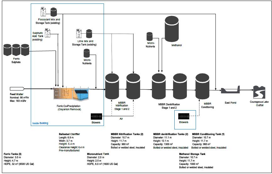
Source: SRK, 2023
| Courageous Lake Project | Page 271 |
| Pre-feasibility Study and Preliminary Economic Assessment NI 43-101 Technical Report | January 5, 2024 |
| Figure 18-17: | Courageous Lake Water Treatment Equipment Dimensions |
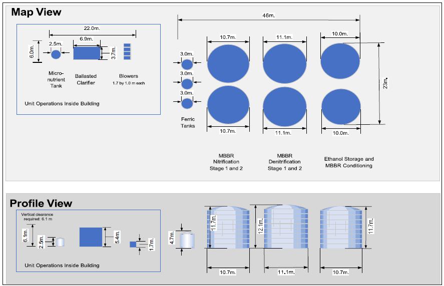
Source: SRK, 2023
| Courageous Lake Project | Page 272 |
| Pre-feasibility Study and Preliminary Economic Assessment NI 43-101 Technical Report | January 5, 2024 |
| 19 | MARKET STUDIES AND CONTRACTS |
No market studies or product valuations
were completed as part of the 2024 PFS. Market price assumptions were based on a review of public information, industry consensus, standard
practices, and specific information from comparable operations in the region.
Gold doré is widely traded
and can be marketed directly from producer to refinery or through third-party trading entities. Valor Gold was not provided with indicative
refining, insurance, or transportation terms. Assumptions for metal payability, refining costs, transportation costs, and insurance costs
were estimated based on a review of information from comparable recent studies. The assumed transportation and refining terms are summarized
in Table 19-1 below, these refining and transport costs are deducted from the payable value of the metal to arrive at net smelter revenue
(NSR). Refining and transportation terms and costs are influenced by global supply and demand and governed by mine and refinery economics
based on metal prices and cost of operation. During operation, these terms may be based on variable annual negotiations, fixed rates,
and/or market benchmarks.
| Table 19-1: | Summary of Assumed Doré Transportation and Refining
Terms |
| Description |
Units |
Value |
| Payability – Au |
% |
99.80 |
| Transportation and refining cost |
C$/oz Au |
5.0 |
| Transportation Insurance |
% (of NSR) |
0.15 |
| 19.2 | Commodity Price Projections |
Project economics were estimated
based on a 3-year trailing average gold price of $1,850/oz and a consensus long term forecast forex (FX) of 0.74 US$/C$. These values
are consistent with historic prices, shown in Table 19-2. The QP also considers the prices used in this study to be consistent with the
range of prices being used for other project studies.
| Table 19-2: | Summary of Historic Commodity Pricing |
| Description |
Units |
Project
Assumption |
1-Year
Average |
2-Year
Average |
| Gold Price |
US$/oz Au |
1,850 |
1,927 |
1,845 |
| Exchange Rate (FX) |
US$/C$ |
0.74 |
0.74 |
0.76 |
No contracts for the transportation
or off-take of the gold doré are currently in place, but if they are negotiated, they are expected to be within industry norms.
Similarly, there are no contracts currently in place for the supply of reagents, equipment, utilities, labour, or bulk commodities required
to construct and operate the Project.
| Courageous Lake Project | Page 273 |
| Pre-feasibility Study and Preliminary Economic Assessment NI 43-101 Technical Report | January 5, 2024 |
| 20 | ENVIRONMENTAL STUDIES, PERMITTING, AND SOCIAL OR COMMUNITY IMPACT |
Courageous Lake is located on lands
within the Treaty 11 Claim, the Akaitcho Traditional Territory, the Wek’èezhìi Resource Management Area, and the Monwhi
Gogha De Nittaee Areas of the Tłıc˛ hǫ Land Claim Agreement, as well as the North Slave Métis traditional lands.
The traditional lands of the NWT Métis Nation lie to the east of the property. Seabridge has actively engaged with Tłıc˛
hǫ Government, the Yellowknives Dene First Nation (YKDFN), Lutselk’e Dene First Nation (LKDFN), North Slave Métis Alliance
(NSMA) and NWT Métis Nation (NWTMN) since acquiring the property.
The Courageous Lake property is
characterized by undulating hills to the west and flat terrain to the east with associated tundra vegetation and exposed bedrock cover.
A low-lying marshy area is associated with Matthews Creek that flows from Matthews Lake across the Courageous Lake deposit in a northwesterly
direction to join Courageous Lake. Matthews Creek is the only discharge out of the Matthews Lake drainage basin.
The property is located north of the
tree line in the zone of continuous permafrost. An esker complex, or long ridges composed of stratified sand and gravel, is situated on
the north shore of Matthews Lake. Lakes and streams contain a variety of fish species, including: arctic grayling, lake trout, round whitefish,
lake whitefish, northern pike, lake cisco, longnose sucker, burbot, brooke and ninespine stickleback, and slimy and spoonhead sculpin.
Caribou, moose, grizzly bear, wolves, foxes, ground squirrels, migratory birds, raptors, and waterfowl have all been observed in the project
area. The project area is located within the historic spring migration range for the Bathurst herd however caribou usage of the area varies
by year and season. Due to the recent shift of the Bathurst herd to wintering on the tundra (rather than below the treeline) caribou may
be observed during winter period and the spring migration may no longer cross the area.
Though the area is remote, the reclaimed
Salmita and Tundra Mines are located a few kilometers to the southeast of the project area, and the reclaimed Courageous Lake underground
exploration site and the flooded RED24 bulk sample open pit are located northwest and west of camp respectively. The active Diavik and
EKATI diamond mines are 75 km northeast of the project site. The Tibbitt to Contwoyto winter ice road connects Yellowknife, NWT, with
these mines 2 months each winter. For the purposes of this study, it is assumed that the Project will establish a spur road to the project
area connect to the seasonal winter road.
| 20.2 | Environmental Considerations |
The Project area has been subject
to regional environmental studies since 1983. The West Kitikmeot Slave Study (WKSS) collected extensive environmental information from
1996 to 2001. An update of the report was done in 2007. The WKSS investigated Traditional Knowledge (TK) and environmental issues in relation
to proposed and existing developments in the Slave Geological province. In 2000 to 2002 a consortium of mining companies conducted a major
environmental investigation of the Tibbitt to Contwoyto Winter Road alignment and surrounding area.
| Courageous Lake Project | Page 274 |
| Pre-feasibility Study and Preliminary Economic Assessment NI 43-101 Technical Report | January 5, 2024 |
In 2004, Seabridge began to collect
environmental data including archaeology, aquatic resources, water quality, hydrology and wildlife. In 2010 Seabridge engaged Rescan,
a Yellowknife-based consulting firm with extensive mining-related EA experience in Canada, and the program was expanded and included:
air quality, noise, meteorology, hydrology, hydrogeology, aquatic resources, fish and fish habitat, terrain and soils, vegetation and
ecosystem mapping, wildlife, wetlands, and archaeology. Since 2012, ERM Consultants Canada Ltd (having acquired Rescan) continued limited
baseline and environmental monitoring of meteorology, wildlife (a wildlife camera program), hydrology, and water quality to address information
required to further advance the Project.
| 20.2.1 | Baseline and Supporting Studies |
The Project is located in northern
Canada, 240 km northeast of Yellowknife. Site elevation is 409 m above mean sea level. The meteorology station, located next to Matthews
Creek, and the camp have collected data since 2007, which is summarized in Table 20-1 (ERM, 2020). Temperatures range from -44.4°C
to +28.5°C; with an average daily mean temperature of -8.6°C. The annual average wind speed is 4.5 m/s with maximum gusts of 21.5
m/s. Average daily mean barometric pressure was 1,013 hPa during 2008 to 2019.
Precipitation at the Project is
relatively low, with the majority of precipitation occurring during the summer months. Total annual water equivalent precipitation recorded
at the site between 2008 and 2019 averaged 221.5 mm (ERM, 2020). Average annual monthly precipitation was 18.5 mm. Regionally, the average
snow depth between October and April ranges between 7-31 cm at Cambridge Bay and between 2-39 cm at Yellowknife (Environment Canada, 2010).
Solar radiation ranges from 3 W/m2 in December to 277 W/m2 in May at Courageous Lake.
| Table 20-1: | Summary of Matthews Creek Station Meteorological Observations |
| Parameter |
Jan |
Feb |
Mar |
Apr |
May |
Jun |
Jul |
Aug |
Sep |
Oct |
Nov |
Dec |
Annual |
| Wind |
| Average Wind Speed (m/s) |
4.65 |
4.31 |
4.56 |
4.74 |
4.8 |
4.61 |
4.39 |
4.38 |
5.05 |
4.69 |
4.08 |
3.89 |
4.51 |
| Average Daily Maximum Wind Gust (m/s) |
9.79 |
9.39 |
9.15 |
9.4 |
9.93 |
10.22 |
10.22 |
9.62 |
10.86 |
9.51 |
8.79 |
7.94 |
9.57 |
| Extreme Maximum Wind Gust (m/s) |
20.74 |
22.91 |
22.83 |
26.24 |
22.05 |
17.99 |
21.23 |
22.5 |
23.4 |
18.62 |
21.21 |
17.84 |
21.46 |
| Air Temperature |
| Extreme Daily Maximum Temperature (°C) |
-3.3 |
-3.7 |
1.4 |
6.5 |
21.1 |
27.9 |
28.5 |
28.3 |
20.5 |
10.4 |
1.5 |
0 |
11.6 |
| Average Daily Maximum (°C) |
-23.4 |
-22.4 |
-16.8 |
-9.9 |
2.9 |
14.2 |
19 |
16.5 |
8.4 |
-2.4 |
-14 |
-21.5 |
-4.1 |
| Average Daily Mean (°C) |
-27.5 |
-27.5 |
-23.1 |
-14.9 |
-2.4 |
9.6 |
14.1 |
12 |
4.8 |
-4.9 |
-17.2 |
-25.6 |
-8.6 |
| Average Daily Minimum (°C) |
-31.5 |
-31.3 |
-27.3 |
-21.1 |
-6.6 |
3.8 |
9.2 |
7.6 |
1.5 |
-7.8 |
-21.9 |
-28.9 |
-12.9 |
| Extreme Daily Minimum Temperature (°C) |
-43.4 |
-42.9 |
-44.4 |
-37.7 |
-25.8 |
-5.6 |
1.7 |
-2.2 |
-9.3 |
-25 |
-38 |
-42.3 |
-26.2 |
| Courageous Lake Project | Page 275 |
| Pre-feasibility Study and Preliminary Economic Assessment NI 43-101 Technical Report | January 5, 2024 |
| Parameter |
Jan |
Feb |
Mar |
Apr |
May |
Jun |
Jul |
Aug |
Sep |
Oct |
Nov |
Dec |
Annual |
| Relative Humidity |
|
|
|
|
|
|
|
|
|
|
|
|
|
| Average Daily Maximum (%) |
95.9 |
94.2 |
97.5 |
98.7 |
96.7 |
99.2 |
94.6 |
97.2 |
99.2 |
99.6 |
98.2 |
96.2 |
97.3 |
| Average Daily Mean (%) |
76.6 |
76.5 |
78.4 |
82.6 |
80.7 |
69.3 |
68.6 |
75.6 |
82.7 |
90.1 |
85.9 |
78.3 |
78.8 |
| Average Daily Minimum (%) |
61.6 |
62.1 |
60.7 |
68.2 |
42.6 |
39.5 |
45.6 |
50.9 |
62.3 |
71.1 |
70.6 |
54 |
57.4 |
| Barometric Pressure |
| Average Daily Maximum (hPa) |
1,037 |
1,036 |
1,038 |
1,036 |
1,031 |
1,030 |
1,026 |
1,027 |
1,027 |
1,032 |
1,040 |
1,043 |
1,034 |
| Average Daily Mean (hPa) |
1,013 |
1,014 |
1,015 |
1,015 |
1,017 |
1,012 |
1,011 |
1,011 |
1,010 |
1,011 |
1,010 |
1,013 |
1,013 |
| Average Daily Minimum (hPa) |
981 |
985 |
981 |
982 |
998 |
991 |
996 |
993 |
988 |
985 |
979 |
979 |
987 |
| Incident Solar Radiation |
| Average Daily Total (W/m²) |
8 |
35 |
112 |
226 |
277 |
260 |
232 |
168 |
90 |
37 |
12 |
4 |
122 |
| Average Daily Maximum (W/m²) |
40 |
113 |
215 |
322 |
397 |
378 |
372 |
295 |
193 |
108 |
49 |
15 |
208 |
| Average Daily Minimum (W/m²) |
1 |
7 |
23 |
107 |
75 |
59 |
32 |
25 |
10 |
8 |
2 |
1 |
29 |
| Water-Equivalent Precipitation |
| Average Monthly Total (mm) |
3.2 |
5.7 |
12.3 |
11.3 |
12.6 |
26.2 |
35 |
46.5 |
37.8 |
29.5 |
0.5 |
0.9 |
18.5 |
| Average Daily Total (mm) |
0.1 |
0.2 |
0.4 |
0.4 |
0.4 |
0.9 |
1.1 |
1.5 |
1.3 |
1 |
0 |
0 |
0.6 |
| Extreme Daily Maximum (mm) |
7.7 |
10.4 |
58.5 |
47.3 |
19.5 |
30.6 |
15 |
26.7 |
62.7 |
25.5 |
1 |
1.9 |
24.9 |
Note: Average values based on hourly
and daily data from January 1, 2008 to June 30, 2019
| 20.2.1.2 | Terrain, Soils, Geology and Geochemistry |
Periodic changes in the global climate
of the Quaternary period (two million to 8.5 thousand years ago) induced four major glaciations. As a result, a vast majority of the study
area is now covered by a veneer of till, an unsorted mixture of coarse angular to sub-angular rock fragments in a finer matrix of silty-clayey
material, which has been deposited by the last glacial ice sheet. Drumlins (hills created by the movement of ice over till material) are
also a common feature of the study area. Glacial till has been occasionally overlain by glaciolacustrine or glaciomarine materials. Sandy
or gravelly materials formed by melt-water streams remained in the area in the form of esker complexes deposited over glacial till or
bedrock.
Rescan conducted soil field surveys
in 2010 and 2011. The results of the preliminary terrain and soil study in the Courageous Lake area suggest that the site geomorphological
and soil characteristics reflect typical features of the Arctic tundra environment (Rescan, 2012f). One quarter of the study area is comprised
of lakes. The land is dominated by gently undulating landscapes and rolling topography. The average slope throughout the land portion
of the study area is 6.9%. Steep slopes are rare and are generally confined to the southern part of the study area.
| Courageous Lake Project | Page 276 |
| Pre-feasibility Study and Preliminary Economic Assessment NI 43-101 Technical Report | January 5, 2024 |
Morainal, glaciofluvial, and organic deposits
dominated the study area. Coarser textured glaciofluvial deposits were scattered over the higher relief areas; whereas finer textured
morainal deposits were found in all slope positions. Organic materials had accumulated in valley bottoms and on plains in depressional
areas.
A total of 240 soil sites were
established and 140 soil samples were collected across 65 of the sites (Rescan, 2012f). This work showed that the rates of soil development
are very slow in the study area. Only peat-derived organic materials accumulate relatively fast. Consistently low temperatures and annual
freeze-thaw cycles lead to the formation of permafrost in the soils and contribute to a suite of soil-forming processes known as cryoturbation.
The dominant soils in the study area are classified as Cryosols, Regosols, and Brunisols. Other less common soils are Gleysols. Analytical
results indicate that the soils in the study area are mildly acidic and, with the exception of organic soils, generally have low organic
carbon content. 29% of soils are characterized by low erosion potential, 38% by moderate erosion potential, and 33% by high erosion potential.
Most soils in the mine site area
are moderately coarse textured (sandy loams and loams) and are mainly associated with morainal deposits found in all slope positions.
Coarser textured glaciofluvial deposits are scattered over the high relief areas. Organic materials have accumulated in valley bottoms
and on plains in depressional areas. Due to low temperatures, soil development is very slow and soils have low carbon development in the
top 10 cm, and 89% of soils were classified as Cryosols. Most soils do not show evidence of significant erosional processes when undisturbed.
Soil salvage, stockpiling and cover placement during reclamation will consider these soil characteristics.
| 20.2.1.3 | Geochemical Source Terms |
Seabridge retained SRK Consulting (Canada)
Inc. (SRK) to complete technical assessments for the PFS update, including:
| ● | geochemical characterization of mined material
including waste rock, tailings, and pressure oxidized ore residuals |
| ● | development of geochemical source terms. |
The characterization of geological
materials and definition of geochemical source terms is important for developing and understanding of the project effects on water quality
during all phases of mine development and into post-closure, such that effective water treatment requirements can be designed, costed
and implemented.
The current understanding of the
metal leaching and acid rock drainage (ML/AR) potential characteristics of waste rock at Courageous Lake is based on acid-base accounting
(ABA) data for 69 rock core samples, eight waste rock and one low-grade ore humidity cell tests (HCTs, operated for 72 to 108 weeks) and
three on-site barrels (leachates collected eight times from June 2011 to June. The humidity cells were discontinued but the barrels remain
intact. This database is complemented by the multi-element geochemical database which in 2012 included data for nearly 15,000 intervals
classified as waste rock. Sulphur content was analyzed for these samples.
The ABA data indicated
that waste rock samples were classified as non-potentially acid generating (non-PAG). The ABA data indicated a strong negative
relationship between sulphur content and ARD potential indicated by neutralization potential (NP) to acid potential (AP) ratio
(NPR). The relationship was used to classify exploration drill core samples using the sulphur content. 98.8% of samples were
classified as non-PAG. On this basis, it was concluded waste rock is non-PAG. ARD potential is greater in the ore due to higher
sulphide content compared to waste rock. Ore is classified as having uncertain ARD potential based on NPR<3 in some samples.
| Courageous Lake Project | Page 277 |
| Pre-feasibility Study and Preliminary Economic Assessment NI 43-101 Technical Report | January 5, 2024 |
Arsenic is enriched in the waste
when compared to global average crustal values. Concentrations range from below 10 mg/kg up to 1%. Arsenic occurs as arsenopyrite and
arsenian pyrite. Leachability of arsenic was confirmed by the HCTs (concentrations up to 0.7 mg/L) and barrels (concentrations up to 0.3
mg/L).
Based on the geochemical characterization
data, the following concepts were carried through to the source terms:
| ● | ARD potential is negligible. The source term
does not need to consider acidification of waste rock. |
| ● | Arsenic is the only trace element that is considered
enriched and needs specific consideration in the waste rock source term. |
| 20.2.1.3.2 | Flotation
Tailings |
The geochemical characteristics
of one sample of rougher flotation tailings is available. The sample contained 0.02% total sulphur which based on undetectable sulphate
occurs as sulphide. Due to a carbonate concentration of 70 kg CaCO3/t, the tailings are classified as non-PAG. The sample
contained arsenic at 183 mg/kg and unquantified traces of arsenopyrite and pyrrhotite. Source terms were derived for runoff from beach
faces and infiltration into the beach of the tailing storage facility. The runoff term indicates concentrations consistent with the negligible
sulphide content. The infiltration term yielded unrealistically high concentrations which could be refined by modelling of water content,
freeze back and oxygen diffusion.
The composition of the POX residual
supernatant was estimated based on geochemical testwork and data from analogous operations.
The Arctic region is
composed of vegetated tundra slopes dotted with lakes and wetland fens. Hydrologic processes are dominated by snow accumulation and
melt, surface runoff, stream flow, and lake hydrology. Most of the annual runoff occurs during freshet and is derived from the
melting snow pack. Late August and September precipitation events can also produce moderate runoff. Following freshet, a period of
low flows typically extends through July and August. Due to the presence of permafrost, there is little to no groundwater support
for smaller streams, although there may be interaction between groundwater systems and larger rivers and/or lakes through taliks or
openings in the permafrost. As a result, baseflow in streams is low and supported only by flow through the shallow upper active
layer of the soil profile (i.e. the only part of the soil profile that melts in the summer months), and by the release of lake
storage from any upstream lakes (Woo, 1990).
| Courageous Lake Project | Page 278 |
| Pre-feasibility Study and Preliminary Economic Assessment NI 43-101 Technical Report | January 5, 2024 |
Matthews Creek flows over the Courageous
Lake deposit. It is therefore necessary to determine the hydrology of the creek in the event of its diversion. A hydrometric station was
established at Matthews Creek in 2005 by Hay and Company Consultants (Hayco), a division of EBA. This station, along with a station on
Courageous Lake, were monitored by Rescan in 2010 and 2011 (Rescan, 2012e). Between 2005 and 2011, runoff for Matthews Creek has ranged
from 96 mm to 60 mm and annual peak flows have ranged from 1.36 m3/s to 0.56 m3/s (EBA, 2010; Rescan, 2012e). The
highest discharges during freshet likely preceded the re-installation of stage monitoring instrumentation each year due to access constraints
(EBA, 2008; Rescan, 2012e). At Courageous Lake, the annual peak flow was estimated at 35.2 m3/s. As demonstrated by the hydrographs
for Matthews Creek and Courageous Lake, the hydrologic information collected over the summer monitoring period clearly demonstrates the
seasonal reduction in water levels and related flow discharges following the spring freshet period. Monitored runoff totals were relatively
low compared to other areas of Canada, but reasonable for this region where normal runoff is in the order of 100 mm annually (Natural
Resources Canada [NRCAN], 1978). Low flows in the Arctic can occur at two different times of year depending on the size of the river and
its drainage area. Smaller streams reach their lowest flows in the open water season in summer or early fall, and then produce no water
flows throughout the winter as cold temperatures and low flows cause the streams to freeze to the channel bottom. It is expected that
most streams in the project area, including Matthews Creek, cease to flow over the winter. Larger rivers may produce flow year-round and
reach their lowest flows during late winter (e.g. April or May).
Lake water quality data were collected
in the project area in 1983 in association with the Tundra and Salmita mines (Kanik and Villamere, 1983; as cited in EBA, 2003). Lake
water quality samples were also collected by EBA for Seabridge in 2004 and 2005. In the summer of 2010 and 2011, Rescan conducted extensive
water quality sampling, collecting data from streams and lakes in the study area (Rescan, 2012a). Data has also been collected by CIRNAC
between 2016 and 2022 as part of the Tundra Mine remediation and post-closure monitoring program The data from these studies indicate
that the lakes in the area were characterized as clear, oligotrophic, low TDS, and had slightly acidic to slightly alkaline water. These
characteristics are typical for lakes in the Slave Geological Province. Water quality differences among the lakes were largely related
to lake morphometry. Deep lakes generally had lower concentrations of all water quality variables, while shallow lakes tended to have
higher dissolved- and/or particulate related water quality variables. This relationship occurred due to the increased interaction of the
sediments with the overlying water in shallow lakes, which resulted in higher and more variable nutrient and metal concentrations.
Stream data collected by Rescan
in 2010 and 2011 indicated that water quality in the study area streams was typical of tundra ecosystems, having low TDS, low alkalinity,
and low nutrients, with pH ranging from slightly acidic to slightly alkaline.
Lake sediment data was
collected in 1983 by Kanik and Villamere (1983; as cited in EBA, 2003, and Miller, et.al, 2019), and by Rescan in 2010 and 2011
(Rescan, 2012a). Sediment quality was driven largely by particle composition. Most lakes had silty sediments with a few sites having
higher sand content. Since metals tend to bind to silt and clay more than they do to sand, the sites with the higher silt/clay
content generally had higher metal concentrations than at the sandy locations. A comparison of sediment quality data to the CCME
Sediment Quality Guidelines for the Protection of Aquatic Life indicated that lakes in the study area tended to have high arsenic
levels. This suggests that high arsenic levels are common and natural in the study area sediments, most likely due to natural
weathering of arsenic-bearing host rock in the area.
| Courageous Lake Project | Page 279 |
| Pre-feasibility Study and Preliminary Economic Assessment NI 43-101 Technical Report | January 5, 2024 |
Fish and fish habitat assessments
were described in relation to the Salmita Mine by Hatfield (1982; as cited in EBA, 2003) and Kanik and Villamere (1983; as cited in EBA,
2003). A fish habitat survey was conducted for Matthews Creek in 2004 (EBA). Monitoring of fish habitat compensation work was carried
out at Matthews Lake and Sandy Lake between 2005 and 2008 (Dillon, 2009). In 2010 and 2011, Rescan completed an extensive baseline program
to assess lakes and streams to the north, east, south, and west of the Courageous Lake deposit; 18 streams and 66 lakes were sampled (Rescan,
2012c). These studies found that many lakes in the project area are not fish-bearing as they are small and shallow. The larger lakes with
extensive shallow, littoral zones and large areas of deep water contained the largest number and most diverse fish communities.
Streams in the area generally contained
poor to fair fish habitat, with the exception of Matthews Creek and other larger streams. These streams contained ample cover and substrate
for spawning and rearing. Pools, which are critical for overwintering and provide cover to fishes, were uncommon. Riffles and glides were
common habitats in streams.
A total of 13 fish species were
captured in lakes and streams since 1983, including: Arctic grayling, lake trout, round whitefish, lake whitefish, northern pike, lake
cisco, longnose sucker, lake chub, burbot, brooke and ninespine stickleback, and slimy and spoonhead sculpin. Of these species, lake cisco,
lake trout, lake whitefish, and round whitefish were predominantly found in lakes. Low species diversity was observed in the lake fish
communities. Matthews Creek provides spawning and nursery habitat for Arctic grayling, northern pike, longnose sucker, slimy sculpin and
burbot. None of the fish species or populations near Courageous Lake are listed under the Committee on the Status of Endangered Wildlife
in Canada (COSEWIC).
| 20.2.1.4.4 | Ecosystems, Vegetation and Wetlands |
Rescan conducted Terrestrial Ecosystem
Mapping (TEM) baseline surveys in the summers of 2010 and 2011 (Rescan 2012g). The baseline analysis indicates that the area is dominated
by upland tundra ecosystems (49% by area) and wetland fens (5%). In the 13 ecosystems that were identified during the TEM surveys, there
were 134 commonly occurring plant species. No invasive plants were identified. A survey completed in 2011 for rare plants identified a
total of 734 vascular plant, bryophyte, and lichen species in the study area, of which 58 are tracked by the NWT General Status Ranking
Program (Government of Northwest Territories – Department of Environment and Natural Resources [GNWT ENR], 2010). No species having
federal status (Committee on the Status of Endangered Wildlife in Canada [COSEWIC]; Species at Risk Act [SARA]) were recorded in the study
area.
Terrestrial ecosystem
mapping indicated that the most common ecosystem association was Scrub Birch – Labrador Tea Tundra, followed by Scrub Birch
– Crowberry Tundra and Mixed Sedge – Sheathed Cottongrass. Wetland studies were completed in the Project area by Rescan
in 2010 and 2011 (Rescan, 2012i). Within the study area, wetlands cover 16% of the landscape. The five federally described wetland
classes were observed; fens and bogs were the most common. One hundred plant species representing 65 genera were identified during
the field surveys. The most common types of vascular plants observed were sedges, dwarf shrubs, shrubs, and cotton grasses. The
common bryophytes included Sphagnum species and hook mosses.
| Courageous Lake Project | Page 280 |
| Pre-feasibility Study and Preliminary Economic Assessment NI 43-101 Technical Report | January 5, 2024 |
| 20.2.1.5 | Wildlife and Wildlife Habitat |
Historically the Bathurst caribou
herd passed through the Project area during both its spring and fall migrations (Gunn et al., 2002) between its wintering grounds below
the treeline and its calving grounds near the Arctic coast. This pattern of movement was also observed by Kanik and Villamere (1983; as
cited in EBA, 2003) who noted herds of up to 2,000 to 3,000 animals in the area during their work in 1981 to 1983. Indications are that
the Bathurst herd has declined from 472,000 ± 72,900 animals in 1986 (Heard and Williams, 1991) to 31,900 ± 11,000 in 2009
(Nishi et al., 2007; GNWT ENR, 2009; GNWT ENR, 2010), and 6,240 animals in 2021 (GNWT ENR 2021). Barren-ground caribou are currently listed
under the Species at Risk (NWT) Act and by the Committee on the Status of Endangered Wildlife in Canada (COSEWIC) as a “threatened”
species in the NWT.
Aerial surveys were flown in 2004
and 2005 by EBA. Caribou abundance within the study area was lower during July and November surveys than compared to the September survey
period when the caribou were moving through the study area toward the treeline to the south (TJS Mining-Met Services et al., 2005). Rescan
conducted aerial surveys in May 2012, and observed caribou moving through the study area toward the calving grounds to the north. In 2010
and 2011, Rescan mapped historical movements of the Bathurst herd from GPS collar data collected by GNWT ENR from 1996 to 2010 for the
Bathurst caribou herd and used remote digital cameras throughout the study area to document caribou movement. The collar maps indicated
that the Bathurst herd generally passes through or at the edge of the Courageous Lake Property during seasonal migration periods en route
between calving and overwintering destinations. The exact migratory route and overwintering locations vary year by year (Rescan, 2012j).
Caribou trails were evident with crossings at Nodinka Narrows across MacKay Lake to the south of the project area and to the north along
the southeast edge of Courageous Lake and suggest the general pattern of movement appears to be on a northwest/southeast axis through
in the project area.
Seabridge has undertaken wildlife
camera studies since 2010 to monitor the timing, abundance, and location of caribou within the Project area, and to examine their use
of areas identified through mapping of caribou trails in 2010. A passive camera monitoring method was selected in lieu of low-level aerial
surveys to reduce disturbance to caribou. The study area extends 60 km north to south and 40 km east to west centered on the Matthews
Lake camp and has averaged more than 60 cameras deployed each year since the study began.
Cameras recorded 6,132
caribou in 1,398 caribou photo events during 53,121 active camera days over the 52 months of the study reported here (between 2019
and 2023), excepting the Covid period of 2020-2021 (ERM 2023). Caribou continue to winter in the vicinity of the Project. Most
caribou photo events were images of single individuals or small groups less than 30 caribou. Caribou calves were not recorded during
the calving, or post-calving seasons in the area around the Project. Caribou observed in the Project area during the calving season
were generally male or sub-adult caribou and no calves were observed, suggesting that the pattern of caribou not calving in the
Courageous Lake area continues (ERM 2019, ERM 2020, ERM 2023).
| Courageous Lake Project | Page 281 |
| Pre-feasibility Study and Preliminary Economic Assessment NI 43-101 Technical Report | January 5, 2024 |
The camera results suggest that
some seasonal patterns are changing. At the beginning of the study (2010 to 2012) the majority of caribou were observed in the summer,
late summer and pre-rut periods as they moved southward to the treeline. Beginning in about 2016, caribou were observed over-wintering
above tree-line rather than below treeline some years. These camera observations are consistent with collar data that show similar winter
patterns. When the caribou wintered below treeline their northward spring migration passed through the Courageous Lake area enroute to
the calving grounds at Bathurst, but more recently when the herd spends winter above treeline it no longer passes through the Courageous
Lake on its spring migration. Some caribou have been observed in the Project area during the calving season, but were generally male or
sub-adult caribou and no calves have been observed, suggesting that the pattern of caribou not calving in the Courageous Lake area continues
(ERM 2019, ERM 2020, ERM 2023).
Several species of carnivorous
mammals occur in the Courageous Lake area including grizzly bear, wolf, and wolverine. Other mammals such as moose, muskox, arctic fox,
red fox, short-tailed weasel, Arctic ground squirrel, and Arctic hare are also common and have been documented on incidental logs.
Prior to 2004, no official grizzly
bear surveys had been undertaken, though incidental sightings of grizzlies had been recorded for the region (Kanik and Villamere, 1983;
as cited in EBA, 2003). Aerial and ground surveys were conducted in 2004 by EBA to document grizzly bear dens occurring on eskers and
other glaciofluvial deposits within the study area. Seven grizzly bears, two new dens, and three old dens were documented in 2004. In
2005, aerial surveys and ground checks were conducted incidentally during other surveys; five bears were observed, and one old bear den
that was not previously noted in 2004 was recorded (TJS Mining-Met Services et al., 2005). Dens not associated with a prominent esker
are located in a mound of glacial-fluvial sediment that facilitate digging. Observations of wolves, wolf activity, and wolf dens were
documented incidentally during other wildlife surveys done by EBA in 2004 and 2005. In 2004, one active den site and one inactive den
site were documented. In addition, 24 observations of wolf signs were recorded including daybeds, scat, and tracks. In 2005, the same
active den site that was recorded in 2004 was being used again. In addition, two old wolf den sites were found in 2005. Two adult wolves
were observed during other wildlife work and were recorded as incidental observations.
| 20.2.1.5.3 | Small Mammals and Birds |
Rescan conducted small
mammal trapping in 2010 to identify species present and monitor relative abundance as an index of prey availability. Only red-backed
voles were observed (Rescan, 2012j). Raptor cliff nesting habitat was assessed during aerial surveys in 2010 and 2011 (Rescan,
2012j) to identify active nesting sites and assess the presence and distribution of raptor species. Nest occupancy surveys were
conducted for raptors. The majority of raptors and habitat were located outside of the project area, with the greatest concentration
of suitable habitat and nests occurring south of MacKay Lake and Warburton Bay (Rescan, 2012j). Two raptor species of conservation
concern were observed during aerial surveys: the peregrine falcon and the short-eared owl. The short-eared owl is listed as
“sensitive” by the NWT and “special concern” by COSEWIC (2022) while the peregrine falcon is listed as
“sensitive” by the NWT and “special concern” on the SARA (2022, c.29) Schedule 3.
| Courageous Lake Project | Page 282 |
| Pre-feasibility Study and Preliminary Economic Assessment NI 43-101 Technical Report | January 5, 2024 |
Rescan conducted water dependent
bird (waterbird) aerial transects and ground surveys in 2010 and 2011 to document species present and to identify important habitat. Canada
geese were the most abundant waterbird species observed, followed by snow geese, greater white-fronted geese and tundra swans. Seven waterbird
species are listed as Sensitive in the NWT: black scoter, horned grebe, lesser scaup, long-tailed duck, yellow-billed loon, white-winged
scoter and northern pintail. The horned grebe is also federally considered as a species of “special concern” by COSEWIC (2009).
In general, total detections and total species of waterbirds were higher during the fall staging surveys. Geese exhibited a preference
for the north shore of Courageous Lake; whereas, diving and dabbling ducks were scattered frequently throughout various lakes in the project
area. Habitat documentation revealed that waterbird staging observations were associated largely with lakes, which highlights the importance
of large lakes for supporting migrating birds in the area (Rescan, 2012j).
Baseline studies were conducted
by Rescan for upland breeding birds (i.e., passerines, shorebirds, ptarmigan, and jaeger) in 2011 to characterize biodiversity, distribution,
and community habitat use. The most frequently observed species were American tree sparrow, followed by Lapland longspur, savannah sparrow,
and Harris’s sparrow. Of the 29 upland breeding bird species observed, five are listed as Sensitive by the NWT General Status Ranking
Program (NWT ENR): American golden-plover, Harris’s sparrow, red-necked phalarope, rusty blackbird, and semipalmated sandpiper.
The rusty blackbird, Harris’ sparrow, and red-necked phalarope are also federally listed on Schedule I as populations of Special
Concern under the SARA.
Radar surveys and accompanying
audio-visual surveys were conducted in 2011 to assess the behaviour of avian species migrating at night. Migration movements of 14 species
were confirmed during the fall, including one waterbird, two raptors, two shorebirds, and nine passerines.
| 20.2.1.6 | Air Quality and Noise |
A dustfall sampling program was
conducted for three months from July to September of 2010. Dustfall samples were analyzed for total dustfall, soluble dustfall, insoluble
dustfall, sulphate, nitrate, various anions, and total metals. Alberta criteria were used for comparison because there are no dustfall
objectives in the NWT. Total dustfall values at Courageous Lake were in conformance with the Alberta criteria for commercial and industrial
areas. However, the Alberta criteria for residential and recreational areas were exceeded at multiple stations throughout the sampling
period (Rescan, 2011).
Baseline noise sampling was conducted
during summer (August) and fall (September) 2010 at locations within the habitat of potentially sensitive wildlife receptors. The 24-hour
90th percentile logarithmic average noise levels from the six sampling locations varied from 15 to 46 dBA and were used to exclude noise
caused by helicopters and aircraft active during exploration in the area (Rescan, 2012d) for baseline records.
| Courageous Lake Project | Page 283 |
| Pre-feasibility Study and Preliminary Economic Assessment NI 43-101 Technical Report | January 5, 2024 |
| 20.2.1.7 | Visual and Aesthetic Resources |
The site is remote from human habitation
and only accessible by aircraft in summer, and aircraft or ice road in winter. Existing landscape features in the study area were documented
in the winter and summer of 2011 (Rescan, 2012h).
The Project is located 3 km south
of a recreational surface lease that was associated with a commercial fishing and hunting camp located on the north shore of the east
arm of Courageous Lake. The camp has not been active for over twelve years and the tents/facilities are in very poor condition. The lease
holder previously approached Seabridge to purchase the lease and associated facilities and equipment.
| 20.2.1.8 | Archaeological and Heritage Resources |
The project area contains many
areas considered to have high archaeological potential. Prehistoric, historic, and traditional sites occur throughout the study area and
most are associated with slightly elevated terrain adjacent to medium and large lakes, on knolls, and on eskers. Seabridge conducts “pre-clearance”
archaeological surveys prior to conducting drill programs or other activities that may result in a surface disturbance.
A total of over 100 archaeological
sites have been recorded in the study area during five years (2003, 2010, 2011, 2012 and 2022) of baseline studies. Archaeological assessment
of the property was initially conducted by Points West Heritage Consulting Ltd. (Points West) in 2003 for Seabridge under NWT Archaeological
Permit 2003-943. Further work was undertaken by Rescan in 2010 under permit 2010-015, and in 2011 under permit 2011-006 (Rescan, 2012b),
and by ERM Consultants Canada Ltd. during 2012, 2013, 2018 Archaeological surveys of the Courageous Lake property were initiated in 2003
and have continued through 2022. As a result of this work, over 175 archaeological and heritage sites have been documented in the area
(Bussey 2003; Seip et al. 2011, 2012, Seip and Campbell 2013, Seip and Walker 2013, Le Beau and Walker 2019) and (ERM 2023).
The known archaeological sites have
been compiled into a GIS database with protective set-backs that range from 25 to 100m depending on the type of site. All archaeological
sites including set-backs have been reported to the GNWT Prince of Wales Northern Heritage Centre and approved.
Prior to development of the Project
all known sites within and adject to the project footprint will need to be revisited and a plan developed for mitigation, if required.
This will be completed and approved as part of the Environmental Assessment process.
In 2022, ERM Consultants Canada
Ltd., conducted a Systematic Data Recovery, and mitigation work at archaeological site LaNv-20. Site LaNv-20 was discovered in 2010 within
and adjacent to the Mathews Lake Camp (which was established in the 1980’s by previous companies). In 2022 seven evaluative units
(EUs - small excavations) and a site survey were conducted, resulting in collection of 211 chipped stone quartzite artifacts, including
131 from 6 EUs, and 80 surface finds collected from 25 locations within the site boundary. Artifacts collected include 12 tools and 199
pieces of debitage. The archaeologist recommended that activities could continue at the camp, however, if the footprint of the camp were
to expand additional surveys and mitigative work would be required.
| Courageous Lake Project | Page 284 |
| Pre-feasibility Study and Preliminary Economic Assessment NI 43-101 Technical Report | January 5, 2024 |
Of the over 175 archaeological
sites recorded during the span of 20 years of baseline studies, most sites contained non-diagnostic artifacts or features; however, based
on diagnostic artifacts located, 18 sites have been tentatively associated with known cultural periods:
| ● | One site has been tentatively identified as a
Shield Archaic site (5,000 – 3,000 B.P.) |
| ● | Four sites contain artifacts that have been
tentatively identified as Arctic Small Tool tradition artifacts associated with pre-Dorset and Canadian Tundra sites (3,500 – 2,500
B.P.) |
| ● | Twelve sites have been tentatively identified
as Taltheilei sites (2,500 – 200 B.P.) |
| ● | One site had both Shield Archaic and Taltheilei
artifacts. |
| 20.2.1.9 | Traditional Use and Traditional Land Use |
The Project is within the traditional
lands of the Treaty 11 Claim, the Akaitcho Traditional Territory, the Wek’èezhìi Resource Management Area and the
Monwhi Gogha De Nittaee Areas of the Tłıc˛ hǫ Land Claim Agreement, as well as the North Slave Métis traditional
lands. The traditional lands of the NWT Métis Nation lie to the east of the property There are no permanent communities in the
vicinity of the project area. The Tłıc˛ hǫ community of Wekweètì, situated 140 km to the west of the
site, with a population of 129 in 2016, is the closest community.
Other Aboriginal communities include Lutselk’e
on Great Slave Lake, 200 km south of the Project, N’dilo in Yellowknife, and Dettah 20 km north of Yellowknife.
Seabridge initiated discussions in
2010 with Indigenous groups who traditionally used the Courageous Lake area to discuss with each group how they would like their Traditional
Knowledge (TK) collected and used to support an environment assessment program that was proposed at the time. As part of the dialogue,
elders from each group with knowledge of the Courageous Lake area were brought to site in 2010, 2011, and 2012 to spend time together
on the land.
Caribou trails, travel corridors,
and crossing points were mapped by Seabridge through aerial surveys conducted in 2010 and reviewed with traditional land users. Input
about how and where the caribou travel was used to design the remote camera monitoring program, which began in 2010 and continues to collect
data today (20.1.1.5.1).
Seabridge sought proposals for TK studies
from each of the following groups: Yellowknives Dene First Nation (YKDFN), the Tłıc˛ hǫ Government, North Slave Métis
Association and Lutselk’e Dene First Nation. Proposals were received from the Tłıc˛ hǫ and Yellowknives. The
Tłıc˛ hǫ study proceeded in 2012, and the YKDFN study began in 2018.
The
Tłıc˛ hǫ TK Study was undertaken with elders from May to December 2012 that included a two-week TK field camp
near Courageous Lake. The report was published and is available online at the TG website (Jacobsen, 2012). The Tłıc˛
hǫ TK report summarizes the cultural significance of the Courageous Lake area, the elders’ environmental knowledge of the
area and presents elders’ concerns and recommendations regarding developments. Traditionally, the Tłıc˛ hǫ
people used the Courageous Lake area during fall and winter to hunt caribou, collect plants for traditional medicines, pick berries
and to fish. Some people would overwinter and continue hunting and trapping then journey back to the treeline area in late winter.
The report describes the elders’ environmental knowledge of the larger region with a focus the fall caribou migration route
from Lac de Gras through Mackay Lake towards Snare River, and the importance of water crossings to the migration. The elders are
concerned with how the animals and the land will impacted by activities, with particular concern regarding the ability of caribou to
migrate westward between Courageous Lake and Mackay Lake.
| Courageous Lake Project | Page 285 |
| Pre-feasibility Study and Preliminary Economic Assessment NI 43-101 Technical Report | January 5, 2024 |
In 2018, the YKDFN submitted a
new proposal for a TK study. The draft YKDFN TK Study describes the Courageous Lake area as an important place for traditional and contemporary
uses that include: hunting, fishing, gathering and tool making. Several campsites, cabins and gravesites were used during historic and
contemporary hunting and trapping activities and are connected by a dense network of trails. YKDFN hunted for caribou, moose, grizzly
bear and trapped for white fox, wolverine and martin throughout the area. While the patterns and intensity of land use in the area have
shifted over time, the area remains culturally important to the Yellowknives. The YKDFN continue to use two permanent camps in the Mackay
Lake area for on-the-land experiences that foster intergenerational teaching and knowledge sharing.
Through these studies, Valor Gold
will be able to understand the traditional and contemporary land uses, including the cultural and historical context of TK. Conversations
between Seabridge and the TK knowledge holders will enable Valor Gold to understand potential impacts of the proposed mine on affected
parties, and guide mitigation measures to avoid, reduce or manage effects.
| 20.2.1.10 | Non-Traditional Land Use |
Hunting, fishing, angling and tourism
outfitters are licensed to operate in the area. The ‘Courageous Caribou Camp’ is located 3 km north of the project site across
Courageous Lake. The camp has not operated in over twelve years and all tents and facilities are in disrepair.
The Matthews Lake camp was established
in the 1970s by early exploration companies working in the region, The camp was purchased by an outfitter in 1993 and operated as ‘Treeline
Lodge’ until it was sold to Seabridge in 2010.
Exploration has taken place in the
region since the 1940s. Several mineral prospects and two previously active gold mines in the area include the Tundra Mine, which operated
between 1962 and 1968, and the Salmita Mine, which operated between 1983 and 1987.
There are no parks or protected areas
or forest-related activities near the Project area.
| 20.2.2 | Closure and Reclamation Plans |
A conceptual closure and reclamation
plan will be required during permitting and environmental assessment and permitting phase. An interim closure and reclamation plan will
be required during construction of the Project, and will need to be revised/updated several times during the life of the mine.
At the end of the mine life, an
approved closure and reclamation plan will be implemented that meets the post-closure land use objectives and satisfies regulatory commitments.
| Courageous Lake Project | Page 286 |
| Pre-feasibility Study and Preliminary Economic Assessment NI 43-101 Technical Report | January 5, 2024 |
Reclamation and closure of the Project
is expected to occur in two phases:
| ● | Active closure, which would
be completed in the 10-year period following the end of mining and processing of ore. During the early years of active closure, personnel
would be present at site year-round until major earthworks and equipment decommissioning has been completed. Later in the active closure
period, a site presence would be limited to the open water season (April through October) when the water treatment plant would be operating. |
| ● | Post-closure, which is
a period of monitoring following active closure. In the post-closure period, personnel would go to site on a monthly or quarterly basis
to collect samples, and to monitor the performance of closure measures. |
Reclamation and closure measures and
an estimate of the closure costs are described in the following sections.
| 20.2.2.1 | Reclamation of Facilities |
Figure 20-1 shows the anticipated
post-closure layout for the Project. Reclamation and closure of the various mine areas are summarized in the following sections.
| 20.2.2.1.1 | Waste Rock and Tailings Area |
The waste rock and flotation tailings
area will be covered by 2 m of overburden and 0.3 m of organic material. The cover is intended to allow rain/snow and permafrost to intrude
into the waste material and thus render it inert. The seasonal thawing of the ground (active layer) would occur within the cover, which
means that the waste rock and co-disposed tailings below the cover would remain frozen year-round. The cover depth is estimated based
on reported active layer thicknesses at other mines in the Courageous Lake region.
The lined POX residuals facility
will be covered by a synthetic liner, 2 m of overburden and 0.3 m of organic material. The intent is to fully entomb the facility and
allow it to freeze below the overburden and organic cover material.
The three open pits will be converted
to pit lakes and interconnected in the closure and post-closure period. The combined flow from the three pits will report to Matthews
Creek. At closure, the total water storage capacity of the pit is 105 Mm3.
Saline water collected from the
main open pit in the last year of operation will be stored temporarily in the West Satellite Pit and then pumped back to the open pit
after mining ends. The pit will then gradually be filled with fresh water sourced from Courageous Lake over the next ten years to develop
a stratified meromictic lake with saline groundwater near the bottom overlain by a fresh water cap. Active filling in the closure period
was proposed to reduce the time it would take for the site to reach it’s closure configuration. This will be done by siphoning 12
Mm3 of water from the lake each year in the open water season. Filling of the open pits is done gradually to limit the potential
effects on fish habitat in Courageous Lake (12 Mm3 corresponds to 5% of the annual flow) and downstream users of the watershed.
| Courageous Lake Project | Page 287 |
| Pre-feasibility Study and Preliminary Economic Assessment NI 43-101 Technical Report | January 5, 2024 |
When the pit lake(s) are fully formed, a channel will be
constructed from the lake that will join Matthews Creek. The channel will be constructed to allow fish passage.
Roads are scarified and capped with available surficial soils.
The surfaces can then be planted/seeded with native species as required.
| Figure 20-1: | Post-closure Layout |
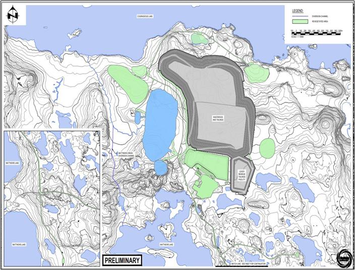
Source: Ausenco, 2023
| Courageous Lake Project | Page 288 |
| Pre-feasibility Study and Preliminary Economic Assessment NI 43-101 Technical Report | January 5, 2024 |
| 20.2.2.2 | Progressive Reclamation |
Valor Gold will reclaim each site
as soon as practically possible after completing a drill hole, access trail or other ground disturbance. Reclamation is completed using
hand tools and in accordance with land use permits and regulatory requirements.
A record of actions on each site
is maintained onsite to ensure that necessary reclamation actions have been successfully completed. Following a winter drill program,
a return to the site during summer snow-free conditions is usually warranted to complete remediation that may not have been possible during
the winter.
Drilling equipment belongs to contractors
and all equipment, pumps, rods, etc. are demobilized at the conclusion of each drill program. Wooden drill shacks, pump shacks, emergency
shelters and unused consumables typically remain in the laydown area at Coreland for use during subsequent drill campaigns.
| 20.2.2.3 | Active Closure Activities |
Active closure activities are summarized
in Table 20-2. For 10 years following the end of mining and ore processing, several reclamation activities will occur to eliminate reliance
on water treatment or other ongoing active closure measures in the post-closure period, to achieve post-closure land use objectives and
to guide post-closure monitoring and maintenance activities (SRK, 2023). Operational experience will inform the ultimate duration of the
period and the scope of the monitoring program which may be adapted over time.
| Table 20-2: | Active Closure Activities and Assumptions |
| Activity |
Timing |
Details/
Assumptions |
| Placement of Closure Covers |
Within 10 years following completion of mine operations |
Placement of 2 m overburden and 30 cm organics on the flotation tailings and waste rock paddock facility. Similar cover materials on the POX Facility following placement of a membrane and trafficable surface; revegetate areas |
| Filling of Open Pit |
Years 1 to 10 following mine operations,
seasonal |
Siphon water from Courageous Lake to fill open pit over a period of 10 years, to occur seasonally during high runoff periods. |
| Filling of Satellite Pits |
2 years |
West and South Satellite Pits fill naturally |
| Outflow from Pit Lakes to Mathews Creek |
Starting in year 11 |
Once the open pit fills, it will discharge to Mathews Creek |
| Reclamation of contact water ponds |
10 years |
Collection of contact water continues until transition water treatment ends (10 years). At the end of the closure transition period, all ponds and final water management structures will be left in place and become part of the post-closure landscape. |
| Remove pipelines and roads |
10 years |
Remove and reclaim disturbance from discharge line, diversion, roads, etc. |
| Decommission and remove all infrastructure such as mill, buildings, camp, fuel farm, mobile equipment, powerline, generators. |
2 - 5 years |
Remove and reclaim lands occupied by infrastructure in accordance with the reclamation and closure plan prescriptions. |
| Reclaim stockpiles and plant site |
2 years |
Overburden
and organic stockpiles will be used for construction of covers. The mill will be demolished, and reusable equipment and scrap hauled
off site. The concrete pad for the plant will remain in place. Approved items may be disposed of in approved open pits to be
flooded. |
| Courageous Lake Project | Page 289 |
| Pre-feasibility Study and Preliminary Economic Assessment NI 43-101 Technical Report | January 5, 2024 |
| Activity |
Timing |
Details/ Assumptions |
| Closure transition water treatment |
10 years |
Continue to treat contact water for 10 years until arsenic and nitrogen species are no longer present in the contact water as no further
blasting occurs after operations; allow for freezing of waste rock dump and reduced arsenic loadings |
Treatment of contact water is expected
to be required for up to ten years after the end of operations. The need to treat water is primarily determined by the extent of permafrost
intrusion into the waste rock and tailings masses. Once the piles have frozen internally, seepage of water from these areas will be minimal
or negligible and at that time water collection and treatment can be discontinued.
In the closure transition period
(up to 10 years), water treatment will be limited to the open water (May to October) each year when surface water is flowing. The annual
treatment campaign will rely on the same treatment process and equipment that was used during the operations phase.
| 20.2.2.4 | Post-Closure Monitoring |
Post-closure monitoring and maintenance
will initially be a continuation of operational monitoring. Programs will evolve over time in response to actual and modelled site conditions
and the informed judgement of qualified professionals. One goal of long-term monitoring and maintenance programs is to verify that site
conditions are evolving as predicted and if not, to adaptively manage them. Long-term monitoring does not mean monitoring in perpetuity.
A secondary goal of the program is to reduce monitoring and maintenance programs once it is appropriate to do so. It is normal and positive
for programs to be rationalized over time. The key items that will require post-closure monitoring include:
| ● | Long-term surface water quality at approved points
of compliance. |
| ● | Geotechnical stability of engineered structures
such as waste rock dumps, engineered covers, dams, water management and conveyance structures. |
| ● | Potential for Metal Leaching/Acid Rock Drainage. |
| ● | Revegetation success, erosion and sediment
control, air quality and dust, wildlife use and other indicators of reclamation success pre-determined or adapted to site conditions. |
| ● | Site access and security. |
Routine reports that document reclamation
progress and performance will be required as conditions of approved permits.
| Courageous Lake Project | Page 290 |
| Pre-feasibility Study and Preliminary Economic Assessment NI 43-101 Technical Report | January 5, 2024 |
| 20.2.3 | Closure Cost Estimates |
A preliminary closure cost estimate
is included in Section 22 per Section 22.1 and Section 22.4, Table 22-1. Provision of US$72M is made for future mine closure and post-closure
costs.
The Project closure cost estimate
will support the development of the final approved mine closure, reclamation and monitoring plan prior to cessation of operations. The
final approved plan will require detailed work breakdowns and detailed costs for the activities listed in Table 20-2, plus all related
mine infrastructure decommissioning, removal or disposal; reclamation activities and post-closure monitoring activities listed in Section
20.1.2.4.
Detailed mine closure and reclamation
cost estimates will determine the financial securities which the mine owner will be required to post. The Mine Site Reclamation Policy
for the Northwest Territories (Indian and Northern Affairs Canada 2002 – now Crown-Indigenous Relations and Northern Affairs Canada
- CIRNAC) outlines the policy and regulatory provisions related to mine site closure and reclamation standards. Every new mining operator
should be able to support and provide security for the cost of reclamation, including shutdown, closure and post-closure, without financial
reliance on the Crown. Financial security requirements will be clearly laid out in water licenses, land leases and other approvals or
agreements. Government tries to avoid overlapping security requirements. Alternate or innovative forms of security may be considered in
addition to standard secure financial instruments. Financial security for new mines must be readily convertible to cash and have the following
basic criteria:
| ● | Subject to applicable legislation and due process,
it must provide the Crown with immediate, unconditional, unencumbered access to the full amount of the security. |
| ● | It must retain its full value through the life of the mine, and if applicable,
beyond. |
| ● | It must remain beyond the control of the mining company, or its creditors
in the event of insolvency. |
Security obligations will involve
discussions and consensus between several government departments and regulatory bodies to coordinate amounts and prevent double-bonding.
| 20.3 | Permitting Considerations |
Mining projects in the NWT are
subject to regulation under federal and territorial legislation to protect workers, the environment, and surrounding communities. This
section discusses the principal licenses and permits required for the Project.
| 20.3.1 | Exploration Permits |
Seabridge maintains a Class A land
use permit for the Courageous Lake property which authorizes exploration activities, such as drilling, winter road construction/maintenance,
fuel storage, and quarrying. Seabridge also maintains two Type B water licenses to use water for drilling, winter road construction, and
potable water at the camp. Water licensing is split between territorial and federal jurisdictions in accordance with the location of water
usage.
| Courageous Lake Project | Page 291 |
| Pre-feasibility Study and Preliminary Economic Assessment NI 43-101 Technical Report | January 5, 2024 |
Other incidental permits which Seabridge
holds include: Archaeological Permit – issued annually to Seabridge’s archaeological consultant, as required, so that field
work such as pre-clearance surveys and site mitigation can be undertaken, and Wildlife Research Permit – issued annually to Seabridge’s
wildlife consultant so that field work, such as remote wildlife camera monitoring can be maintained.
Upon completion of the spin-out, Valor
Gold will effectively takeover the rights and obligations of the permits.
| 20.3.2 | Environmental Assessment |
Part 5 of the MVRMA, established an
environmental assessment process comprised of initial screening, followed by an Environmental Assessment (EA), and-or-an Environmental
Impact Review (EIR) depending on the scale of project impacts. The Canadian Impact Assessment Act (1992, c. 37) in the NWT, does not apply
to the Project specifically.
The formal EA of the Project commences
with an application to the Mackenzie Valley Land and Water Board (MVLWB) for a water license and a land use permit. After a preliminary
screening, the Project will be referred to the MVEIRB, an independent body set up under the MVRMA to conduct environmental assessments
of projects in the NWT referred to it by the MVLWB, or any other regulatory agencies involved.
The EA is conducted in several phases
including:
| ● | Developer’s Assessment Report (DAR) |
| ● | Report of Environmental Assessment by the Review Board |
| ● | Decision by the federal Minister and responsible ministers. |
If deemed necessary, the development
proposal may be referred for an EIR comprising similar phases as the EA, but with an additional level of review conducted by a Review
Panel in a process that includes public hearings. The EIR is documented in an Environmental Impact Statement (EIS) that is submitted to
the Responsible Minister for decision-making.
| Courageous Lake Project | Page 292 |
| Pre-feasibility Study and Preliminary Economic Assessment NI 43-101 Technical Report | January 5, 2024 |
| 20.3.3 | Permits Required for Project Development |
A license, permit, or
other authorization required for carrying out a development such as the Project, may not be issued under any federal or territorial
law unless the environmental assessment requirements of Part 5 of the MVRMA has been complied with in relation to the development.
Once a project has received federal ministerial approval under the process managed by MVEIRB, it is referred back to the MVLWB for
processing of the original license and/or permit applications that triggered the environmental assessment. Permitting by other
agencies may also proceed.
Valor Gold will continue to routinely
meet with representatives of Federal and Territorial government institutions regarding the project and exploration programs on the Project
site. Institutions included: the Mackenzie Valley Land and Water Board, Government of the Northwest Territories, Department of Industry,
Tourism and Investment, Department of Environment and Climate Change; Crown-Indigenous Relations and Northern Affairs Canada, Fisheries
and Oceans Canada, and Prince of Wales Northern Heritage Center. Engagement activities with the Tłıc˛ hǫ Government
are considered in the context of engagement with Indigenous groups.
Upon completion of the spin-out,
Valor Gold will continue to uphold and build upon the relations built by Seabridge.
Table 20-3 presents a list of licenses and permits
that may be required to develop the Project.
| Table 20-3: | Permits and Licenses that will be Required to Develop
the Project |
| Permits
and Licenses |
Purpose |
Enabling
Legislation |
| Ministerial Approval – delegated to GNWT Environment and Climate Change |
Environmental Assessment |
MVRMA
(1998, c. 25) |
| Class A Water License(s) |
Use of water, deposit of wastes |
Waters Act (2014, c.18) and Waters Regulations, and the MVRMA and Mackenzie Valley Federal Areas Waters Regulations (MVFAWR) |
| Type A Land Use Permit |
Use of Land |
Mackenzie Valley Resource Management Act and Mackenzie Valley Land Use Regulations |
| Surface Lease(s) |
Long term (exclusive) right to Crown land to place improvements |
Territorial Lands Act and
Northwest Territories Lands Act |
| License of Occupation |
Non-exclusive use or establishment of linear features on Crown land such as winter roads, airstrips |
Territorial Lands Act and
Northwest Territories Lands Act |
| Mineral Lease |
Long term right to defined mineral resource |
Mineral
Resources Act (2019) and Regulations1 |
| Production License |
Authorizes mineral production obligations on Mineral Lease |
Mineral Resources Act (2019) and Regulations |
| Quarry Lease(s) or Permit(s) |
Non-exclusive use of surficial sand and gravel resources |
Territorial Lands Act |
| Harmful Alteration Disruption or Destruction (HADD) of Fish Habitat |
Impacts to fish and fish habitat |
Fisheries Act (1996, c. 149) |
| Wildlife Permits and Licenses |
To conduct wildlife research, wildlife capture and handling |
Wildlife Act, Wildlife License and
Permit Regulations |
| Disposal of Effluent from Mining Operations |
Deposit of tailings/wastes into water |
Metal and Diamond Mining Effluent Regulations |
| Tailings, waste disposal, mine buildings |
Construction and use of facilities |
Territorial Lands Act and
Northwest Territories Lands Act |
| Courageous Lake Project | Page 293 |
| Pre-feasibility Study and Preliminary Economic Assessment NI 43-101 Technical Report | January 5, 2024 |
| Permits and Licenses |
Purpose |
Enabling Legislation |
| Air permit |
Air emissions management |
NWT
Environmental Protection Act Air Regulations1 |
| Explosives Factory License |
Manufacture of explosives |
Explosives Act (1985, c. E-17) |
| Ammonium Nitrate Storage Facilities |
Storage of products used for manufacture of explosives |
Canada Transportation Act (1996, c. 10) |
| Radio Licenses |
Communications |
Radiocommunication Act (1985, C. R - 2) |
| Radioisotope License |
Use of nuclear density gauges and X-ray analyzer |
Atomic Energy Control Act (1997, c. A-19, s. 1) |
| Benefits Agreement(s) with Indigenous Governments and Organizations |
Requirement to ensure accrual of project benefits to Indigenous peoples |
Mineral Resources Act (52.1) and Regulations |
Note:
| 1. | The Mineral Resources Act Regulations and NWT EPA Air Regulations
are currently under development. |
| 20.4 | Social Considerations |
Seabridge and Valor Gold acknowledges
that the Project is located on the traditional lands of Indigenous Peoples and recognizes the importance of engaging with these parties
throughout the various phases of project activities.
The Mackenzie Valley Land and Water
Board have set out requirements for engagement and consultation related to permit and license applications in Northwest Territories (MVLWB,
2018). For the purposes of this report, engagement is considered outreach activities that are undertaken by Seabridge with Indigenous
groups and stakeholders. In addition, the Crown has a duty to consult with Indigenous groups, and where appropriate, accommodate, when
it has any knowledge that the decisions it is considering may affect an established or potential Indigenous or treaty right as per the
direction provided by the Supreme Court of Canada (Haida Nation v. British Columbia, 2004). In the Northwest Territories, CIRNAC, (on
behalf of Federal government) and various GNWT departments undertake consultation with Indigenous groups on behalf of the Crown, and CIRNAC
has the ultimate responsibility to assess the adequacy of Crown consultation before a final decision or recommendation is made. The MVLWB
and the MVEIRB also have statutory requirements for consultation (such as public hearings) and are required to assess the adequacy of
engagement activities by an applicant/proponent as part of the permitting process, who discharges this duty on behalf of the Crown, require
project proponents to undertake the necessary engagement with potentially affected Indigenous groups, which record then becomes the basis
of Crown consultation.
Upon completion of the plan of
arrangement, Valor Gold will assume the obligations of Seabridge with indigenous groups and other stakeholders.
Seabridge has corporate governance
policies and systems in place that support their social license activities and track their performance. Specific to Courageous Lake, Seabridge
has an Engagement Plan that has been reviewed by Indigenous groups, approved by the MVLWB and updated annually since 2013. The Engagement
Plan is designed to support Seabridge in establishing and maintaining constructive relationships with potentially affected parties by
ensuring a consistent, comprehensive, coordinated and culturally appropriate approach is used during engagement activities.
| Courageous Lake Project | Page 294 |
| Pre-feasibility Study and Preliminary Economic Assessment NI 43-101 Technical Report | January 5, 2024 |
Seabridge and Valor will continue
to build collaborative and cooperative relationships with relevant Treaty, First Nations, and Métis people (as identified by the
Crown), other communities, and interested stakeholders. Seabridge and Valor recognize that its social license to operate is dependent
on being a good corporate citizen and neighbour to all groups with interests in the region. Seabridge and Valor further recognize that
Aboriginal groups maintain a strong stake in both cultural and economic activity in the NWT and are closely involved in regulatory and
permitting activities. Seabridge documents its engagement efforts and activities and is committed to ensure:
| ● | communities benefit from employment, training, and contracting opportunities |
| ● | potential negative impacts are mitigated |
| ● | social concerns are accommodated in project design and managed through best
efforts |
| ● | commitments are respected. |
Seabridge has not entered into
negotiations with any NWT Indigenous Group, including Tłıc˛ hǫ First Nation, with regard to social or economic benefit
agreements for the Project. Other mining and resource developments projects in the NWT have negotiated agreements with groups in the past,
and it is realistic to assume that one or more benefit agreement(s) will be required prior to development of this Project
| Courageous Lake Project | Page 295 |
| Pre-feasibility Study and Preliminary Economic Assessment NI 43-101 Technical Report | January 5, 2024 |
| 21 | CAPITAL AND OPERATING COSTS |
The capital and operating cost estimates presented
in this PFS provide substantiated costs that can be used to assess the economics of the Project. The estimates are based on an open pit
mining operation, a process plant, as well as associated tailings facilities and infrastructure.
The estimates conform to Class
4 guidelines for a PFS-level estimate with a -20%/ +25% accuracy according to AACE International. Both estimates were developed in Q4
2023 C$ based on the proposed design for the Project, with input data from budgetary quotations for equipment, service contracts, and
construction contracts; as well as Ausenco’s in-house database of similar projects and studies, which includes experience from similar
operations. Pricing has been converted from C$ to US$ using an exchange rate of 0.74 for use in financial analyses and publication within
this report.
The capital and operating estimates were prepared or advised
by the following groups:
| ● | Mining is prepared by MMTS. |
| ● | Process Plant, On-site Infrastructure, Tailings Facility, Consumables, and
G&A are prepared by Ausenco. |
| ● | Power Generation is prepared by Brazier Associates. |
| ● | Water Treatment Plant is prepared by SRK. |
| ● | Airstrip is prepared by Ausenco, using the design, earthworks MTO and equipment
costs provided by Tetra Tech. |
| ● | Owner’s Costs are prepared by Seabridge. |
| ● | Closure costs are prepared by Ausenco. |
All cost amounts expressed are in US$ unless stated otherwise.
| 21.2.1 | Basis of Capital Cost Estimate |
The following parameters and qualifications are considered
in preparing the capital cost estimates:
| ● | No allowance has been made for exchange rate fluctuations. |
| ● | Growth allowances are included. |
| ● | Freight costs have been included as a percentage
to each direct cost item. Import duties are excluded from the estimate. |
| ● | Construction
is assumed to be 24 months beginning in January when the TCWR is open for use. |
| Courageous Lake Project | Page 296 |
| Pre-feasibility Study and Preliminary Economic Assessment NI 43-101 Technical Report | January 5, 2024 |
Data for the estimates have been obtained from numerous
sources, including:
| ● | general arrangement drawings |
| ● | mechanical and electrical equipment lists |
| ● | pre-engineering and modular building pricing |
| ● | camp and services pricing |
| ● | contractor’s cost data from recent similar projects. |
Major cost categories (permanent
equipment, material purchase, installation, subcontracts, indirect costs, and owner’s costs) were identified and examined. Growth
was allocated to each of these categories on a line-item basis based on the accuracy of the data. An overall contingency amount was also
derived in this fashion.
Vendors and contractors were requested
to price in native currency. Pricing has been converted from C$ to US$ using an exchange rate of 0.74.
| 21.2.2 | Capital Cost Estimate Summary |
The estimate includes mining, processing,
on-site infrastructure, tailings and waste rock facilities, off-site infrastructure, project indirect costs, project delivery, owner’s
costs, and contingency. The total capital cost summary is presented in Table 21-1. The total initial capital cost for the Project is US$747
M and LOM sustaining costs are US$293 M. Closure costs are estimated at US$72 M, with salvage credits of US$19 M.
| Courageous Lake Project | Page 297 |
| Pre-feasibility Study and Preliminary Economic Assessment NI 43-101 Technical Report | January 5, 2024 |
| Table 21-1: | Summary of Total Capital Costs |
| WBS
Description |
Initial
(US$ M) |
Sustaining
(US$ M) |
Total
Cost
(US$ M) |
| Mining |
89 |
156 |
245 |
| Process Plant |
204 |
48 |
252 |
| Tailings Facility |
35 |
21 |
56 |
| On-Site Infrastructure |
98 |
11 |
109 |
| Off-Site Infrastructure |
45 |
37 |
82 |
| Subtotal Direct Costs |
471 |
273 |
744 |
| Project Indirects |
146 |
7 |
153 |
| Owner’s Costs |
25 |
- |
25 |
| Contingency |
105 |
13 |
118 |
| Project
Total |
747 |
293 |
1,040 |
Note: Values may not sum due to rounding
| 21.2.3 | Area 1000 – Direct Costs, Mining |
The mining cost breakdown is shown in Table 21-2.
| Table 21-2: | Mining Capital Cost Estimate |
| Mining
Capital Category |
WBS |
Initial
(US$ M) |
Sustaining
(US$ M) |
Total Cost
(US$ M) |
| Mine Infrastructure and Services |
1200 |
12 |
9 |
21 |
| Surface Mining |
1300 |
77 |
147 |
224 |
| Total |
89 |
156 |
245 |
Note: Values may not sum due to rounding
| 21.2.3.1 | Basis of Estimate |
Unit costs for consumable and labour rates are estimated
from the sources listed below while the magnitude of consumables and labour requirements are determined for each specific activity from
experience and first principles.
The unit costs are based on the following data:
| ● | Salaries for the supervisory
and administrative job categories are based on MMTS’s experience of similar functions in Canadian mines. An average burden rate
of 56.7% was applied to base salaries to include all statutory Canadian holidays, social insurance, medical and insurance costs, pension,
and vacation costs. In addition, an allowance is included in the burden for increased labour costs due to the cold and remote location. |
| ● | For hourly employees, general
labour rates provided by Ausenco. An average burden rate of 56.7% is applied to base wages to include all statutory Canadian holidays,
social insurance, medical and insurance costs, pension, and vacation costs. In addition, an allowance is included in
the burden for increased labour costs due to the cold and remote location. |
| Courageous Lake Project | Page 298 |
| Pre-feasibility Study and Preliminary Economic Assessment NI 43-101 Technical Report | January 5, 2024 |
| ● | Unit costs are based on
mine designs, calculated equipment productivities and the corresponding mine schedule. Equipment productivities consider the haul distance
between the pit and rock storage piles, as well as stockpile locations. |
| ● | Unit costs freight for
all consumables, tires, and fuel, are based on budgetary quotations. The long-term fuel price is estimated at a delivered cost to site
of C$1.64/L. |
| ● | All mine equipment is planned as diesel hydraulic. |
| ● | Mining equipment consumables,
major equipment replacements, sustaining capital, labour loading factors, equipment life, and costs are based on vendor information and
MMTS’s database from similar mining operations. |
The MMTS estimate of start-up capital
costs includes the following:
| ● | Mine mobile equipment fleet. |
| ● | Support and auxiliary equipment. |
| ● | Fleet and drill monitoring and management software and systems. |
Mine mobile equipment capital costs
are shown in Table 21-3. The mobile equipment capital schedule assumes all major equipment is leased. The assumed leasing terms are a
20% deposit and a 10% interest rate, spread over 6 years with a zero residual value.
| Table 21-3: | Mine Mobile Equipment Capital Schedule |
| Equipment |
Total Cost (including
delivery and
assembly) (‘000s) US$ |
Lease
Down Payment (‘000s) US$ |
| Production Drills (165 mm holes) |
1,721 |
344 |
| Secondary Drills (50 mm holes) |
439 |
88 |
| Grade Control Drill (144 mm) |
1,426 |
285 |
| 12
m3 bucket diesel hydraulic Excavator |
3,257 |
651 |
| 12
m3 bucket wheel loader |
2,610 |
522 |
| Rigid Frame Diesel Haul Truck, 90 t payload |
2,894 |
579 |
| Track Dozer, 450 kW |
1,643 |
329 |
| Track Dozer, 325 kW |
1,191 |
238 |
| Wheel Dozer, 370 kW |
1,949 |
390 |
| Hydraulic
backhoe Excavator, 4 m3 bucket |
988 |
198 |
| Hydraulic
backhoe Excavator, 3 m3 bucket |
744 |
149 |
| Courageous Lake Project | Page 299 |
| Pre-feasibility Study and Preliminary Economic Assessment NI 43-101 Technical Report | January 5, 2024 |
Mine capital costs are derived
from a combination of supplier quotes and historical data collected by MMTS. This includes labour, maintenance, major component repairs,
fuel, and consumables costs. The mine equipment capital costs include costs of delivery to a specified marshalling point and assembly.
The major equipment is leased in this study. All lease payments are assumed to be capital.
Ausenco has provided an allowance
for mine infrastructure buildings and winter ice road delivery costs. The capital cost estimates do not include taxes or duties. The mine
direct capital costs are shown in Table 21-4.
| Table 21-4: | Mine Direct Capital Costs |
| Mine
Capital Costs |
WBS |
US$
M |
| Pre-production Mining |
1320 |
48 |
| Mobile Equipment |
1360 |
157 |
| Surface Mining General |
1380 |
17 |
| Mine Explosives |
1220 |
10 |
| Dewatering, Run off and sedimentation Ponds |
1340 |
1 |
| Other Mine Infrastructure |
1270 |
11 |
| Total Mine Capital Costs |
245 |
Note: Values may not sum due to rounding
| 21.2.3.2 | Mine Infrastructure Buildings |
Mine infrastructure capital covers bulk
earthworks and concrete in addition to the following buildings:
| ● | explosive/magazine
manufacturing and storage facilities. |
The estimate for these buildings totals US$10.8 M.
| Courageous Lake Project | Page 300 |
| Pre-feasibility Study and Preliminary Economic Assessment NI 43-101 Technical Report | January 5, 2024 |
| 21.2.4 | Area 2000-3000 – Direct Costs, Process Plant and Tailings Facility |
The definition of
process equipment requirements was based on process flowsheets and process design criteria, as defined in Section 17. All major
equipment is sized based on the process design criteria to derive a mechanical equipment list. Mechanical scopes of work were
developed and sent for budgetary pricing to equipment suppliers. For mechanical equipment costs, 95% of the value is sourced from
budgetary quotes. Where budget quotes were not obtained, existing Ausenco data base pricing is used from other recent estimates and
projects.
Similarly, the major electrical
equipment is sized based on the project’s equipment list. Scopes of work were developed to receive budgetary pricing from equipment
suppliers. For the electrical equipment, 83% of the value was sourced from budgetary quotations. Where budget quotes were not obtained,
existing Ausenco data base pricing has been used from other recent estimates and projects.
All concrete quantities were estimated
by material take-offs from the general arrangement drawings and benchmarked against Ausenco’s historical data for similar projects.
MTOs for major structures including foundations, footings, walls, pedestals, slab on grade and elevated concrete, detailed excavation,
detailed backfill have been developed based on these calculations.
Budget pricing was sourced on recent
quotes from the market for supply, delivery, and installation of batched concrete. The concrete is inclusive of mobilization and demobilization
and the following:
| ● | The cost of supply and operation of batch plant
including costs for the supply of cement and sand) and winterization costs are included. |
| ● | The cost of materials includes formwork, required embedment’s and reinforcement
steel. |
| ● | The cost for labour includes categorized installation
hours multiplied by the productivity factor, direct labour rate and distributable rate based on recent contractor quotes. |
All structural steel quantities
were estimated by quantity take-offs from the model and/or historical data from other Ausenco projects by the structural department. Structural
steel MTOs include light, medium, heavy and extra heavy structural steel designations and miscellaneous steel including, grating and handrail
and stair treads for all platforms and equipment support steel where not included with the vendor equipment supply scope. Therefore, Ausenco
carried unit rates and installation hours based on recent contractor quotes for projects in the region.
An allowance for the platework
(chutes, bins, distribution boxes, launders, and shop-fabricated and field-erected tanks) has been developed by factoring the total installed
mechanical by WBS level 3. A blended factor is carried in the estimate and aligns with Ausenco’s historical data and actual platework
costs from the construction of recent projects.
An allowance for process plant
piping (pipe, fittings, supports, valves, paint, special pipe items and flanges), instrumentation and remaining electrical bulks (cable
trays, terminations, small lighting, and receptacles) has been developed by factoring the total installed mechanical by WBS level 3. A
blended factor for each is carried in the estimate and aligns with Ausenco’s historical data and actual electrical bulk costs from
construction of recent projects.
The oxygen plant will be leased
and so the yearly lease costs have been put into the sustaining costs for WBS 2800 – Process Plant Services.
The process and tailings facilities
capital cost breakdown is shown in Table 21-5 and Table 21-6 respectively.
| Courageous Lake Project | Page 301 |
| Pre-feasibility Study and Preliminary Economic Assessment NI 43-101 Technical Report | January 5, 2024 |
| Table 21-5: | Process Direct Capital Cost Estimate |
| Process
Capital Category |
WBS |
Initial
(US$
M) |
Sustaining
(US$ M) |
Total Cost
(US$ M) |
| Crushing |
2100 |
20 |
- |
20 |
| Stockpile and Reclaim |
2200 |
10 |
- |
10 |
| Grinding |
2300 |
30 |
- |
30 |
| Flotation and Regrind |
2400 |
19 |
- |
19 |
| Concentrate Pre-Treatment |
2500 |
75 |
- |
75 |
| Merrill Crow Refinery |
2600 |
18 |
- |
18 |
| Neutralization, Cyanide Detox and Tailings |
2700 |
4 |
- |
4 |
| Process Plant Services and Common |
2800 |
27 |
48 |
76 |
| Total |
204 |
48 |
252 |
Note: Values may not sum due to rounding
| Table 21-6: | Tailings Direct Capital Cost Estimate |
| Tailings
Capital Category |
WBS |
Initial
(US$
M) |
Sustaining
(US$ M) |
Total
Cost
(US$ M) |
| Tailings and Waste Rock Co-disposal |
3100 |
35 |
21 |
56 |
| Total |
35 |
21 |
56 |
| 21.2.5 | Area 4000 – Direct Costs, On-site Infrastructure |
The on-site infrastructure is grouped into the following
main categories:
| ● | Bulk earthworks – WBS 4100 |
| ● | Power station – WBS 4200 |
| ● | HV Power Switchyard and Power Distribution – WBS 4300 |
| ● | Site Services – WBS 4400 |
| ● | Infrastructure buildings – WBS 4600 |
| ● | Permanent Accommodation Camp – 4700 |
| ● | Site Water Management – WBS 4800 |
| ● | Mobile equipment (process plant) – WBS 4900 |
| Courageous Lake Project | Page 302 |
| Pre-feasibility Study and Preliminary Economic Assessment NI 43-101 Technical Report | January 5, 2024 |
The on-site infrastructure cost breakdown is shown in Table
21-7.
| Table 21-7: | On-site Infrastructure Direct Capital Cost Estimate |
| On-site
Infrastructure Capital Category |
WBS |
Initial
(US$
M) |
Sustaining
(US$ M) |
Total Cost
(US$ M) |
| Bulk earthworks |
4100 |
9 |
- |
9 |
| Power station |
4200 |
2 |
- |
2 |
| HV Power Switchyard and Power Distribution |
4300 |
2 |
- |
2 |
| Site Services |
4400 |
46 |
- |
46 |
| Infrastructure buildings |
4600 |
26 |
- |
26 |
| Permanent Accommodation Camp |
4700 |
4 |
11 |
15 |
| Site Water Management |
4800 |
6 |
- |
6 |
| Mobile equipment (process plant) |
4900 |
4 |
- |
4 |
| Total |
98 |
11 |
109 |
Note: Values may not sum due to rounding
All earthwork quantities were estimated
from quantity take-offs from the Civil 3D software model and/or engineering calculations from 2D drawings (which come from Civil 3D model)
by the civil/structural department, except for mining and the air strip. Sub-contract rates are used in the estimate for bulk earthworks
requirements. Prices carried in the estimate are based on Ausenco’s historical rates for recent projects in the area.
The estimate includes concrete,
mechanical equipment and electrical equipment required to facilitate the on-site power station, excluding the module power station itself
which is covered under WBS 5300 – Power Supply.
| 21.2.5.3 | HV Power Switchyard and Power Distribution |
The estimate includes a 4.16 kV process
area transformer and 7 km of 13.8 kV overhead distribution power lines.
This estimate includes fuel storage
tanks, fuel pumps and dispensing stations, off-plot piping, fire and water protection allowance, site communication allowance, and all
concrete and steel requirements for the fuel farm and water treatment plant.
| 21.2.5.4.1 | Water Treatment Plant |
SRK developed the estimate for water
treatment plant.
| Courageous Lake Project | Page 303 |
| Pre-feasibility Study and Preliminary Economic Assessment NI 43-101 Technical Report | January 5, 2024 |
| 21.2.5.5 | Infrastructure Buildings |
The estimate includes the supply
and installation of all the buildings within the process plant area and on-site infrastructure.
Building datasheets were developed
to describe the requirements of the building, including sizing, load requirements, and features. Datasheets are included with the contract
packages as a basis for detailed design.
Costs for new ancillary facilities to the
process plant and mine were based on Ausenco’s historical data for similar previous studies. Pricing includes for supplying and
delivering all materials, plant, equipment, tools, facilities, labour supervision, overhead, and all other items and services required
to complete the works.
| 21.2.5.6 | Permanent Accommodation Camp |
A 204 bed permanent accommodation
camp will be located south of the process plant. The camp will be installed at the beginning of construction to house construction personnel
and will then be maintained for operating staff.
| 21.2.5.7 | Site Water Management |
The estimate includes all costs associated with the preparation
of the surface water collection ponds and channeling.
| 21.2.5.8 | Mobile Equipment (Process Plant) |
The mobile equipment fleet is for
supporting the ongoing operations of the process plant (i.e.. bus, fire truck, ambulance, forklift, loader etc.).
| 21.2.6 | Area 5000 – Direct Costs, Off-site Infrastructure |
The off-site infrastructure capital cost estimate is grouped
into the following three main categories:
| ● | Main Access Road – WBS 5100 |
The cost breakdown is shown in Table 21-8.
| Table 21-8: | Off-site Infrastructure Direct Capital Cost Estimate |
| Off-site
Infrastructure Capital Category |
WBS |
Initial
(US$
M) |
Sustaining
(US$ M) |
Total Cost
(US$ M) |
| Main Access Road |
5100 |
4 |
- |
4 |
| Water Supply |
5200 |
- |
- |
- |
| Courageous Lake Project | Page 304 |
| Pre-feasibility Study and Preliminary Economic Assessment NI 43-101 Technical Report | January 5, 2024 |
| Off-site
Infrastructure Capital Category |
WBS |
Initial
(US$
M) |
Sustaining
(US$ M) |
Total Cost
(US$ M) |
| Power Supply |
5300 |
20 |
37 |
57 |
| Airstrip |
5400 |
20 |
- |
20 |
| Total |
45 |
37 |
82 |
Note: Values may not sum due to rounding
The estimate includes all earthworks pertaining to the construction
of the main access road.
All water supply costs are included in WBS 4400 – Site
Services and WBS 4800 – Site Water Management.
The estimate includes the module
diesel power plant supply (7 generators) including engineering, installation, and construction management. The genset supply equipment
costing used is lease to own with 25% up front (initial capital) with the remaining cost paid in 6 annual payments (sustaining capital).
All other associated costs are up front (initial capital).
This estimate includes the off-runway
extension and infrastructure upgrades to the runway using the design, earthworks MTO and equipment costs provided by Tetra Tech.
| 21.2.7 | Area 6000 to 9000 – Project Indirects |
The indirect costs include project indirect costs, owner’s
costs and contingency, as outlined below.
Project indirect costs include following:
| ● | miscellaneous
distributable costs |
| ● | commissioning
representatives and vendor assistance |
| ● | first
fills and initial charges |
| ● | temporary
construction facilities |
| ● | project delivery (EPCM). |
| Courageous Lake Project | Page 305 |
| Pre-feasibility Study and Preliminary Economic Assessment NI 43-101 Technical Report | January 5, 2024 |
Owner’s costs include the following:
| ● | owner’s team and expenses |
Indirect costs are summarized in Table 21-9 and are described
in the following sections.
| Table
21-9: | Total
Indirect Costs |
| Description |
WBS |
Initial
(US$ M) |
Sustaining
(US$ M) |
Total
Cost (US$ M) |
| Project Indirects |
6000 |
146 |
7 |
153 |
| Owner’s Costs |
8000 |
25 |
- |
25 |
| Contingency |
9000 |
105 |
13 |
118 |
| Total Indirect Capital Cost |
276 |
20 |
296 |
Note: Values may not sum due to rounding
| 21.2.7.1 | Area 6000-7000 – Project Indirects |
| 21.2.7.1.1 | Temporary Construction Facilities and Services |
Project preliminaries are items or services which are not
directly attributable to the construction of specific physical facilities of plant or associated infrastructure but are required to be
provided as support during the construction period.
These costs include the following:
| ● | Temporary
construction facilities - site offices, induction center, first aid facilities, administration, portable toilets, temporary fencing,
temporary roads, and parking. |
| ● | Temporary
utilities – power supply, temporary grounding and generators, construction lighting, and water supply. |
| Courageous Lake Project | Page 306 |
| Pre-feasibility Study and Preliminary Economic Assessment NI 43-101 Technical Report | January 5, 2024 |
| ● | Construction
support – site clean-up and waste disposal, material handling, maintenance of buildings and roads, testing and training, service
labour, site transport, site surveys, QA/QC, and security. |
| ● | Construction
equipment, tools, and supplies purchased by the owner or construction management (CM) contractor – heavy equipment and cranes,
large tools, consumables, scaffolding, and purchased utilities. |
| ● | Material
transportation and storage incurred by the owner or CM contractor – all types of freight, agents, staging, and marshalling. |
| ● | Site
office – Local services and expenses, communications, and office furniture. |
| 21.2.7.1.2 | Construction Camp |
The costs for establishing a construction
camp facility, messing, and operations are included in the cost estimate.
The temporary construction camp
will be rented from the beginning of the construction period; a total of 560 beds are required to cover all the third parties’ personnel
in the scope of work and including the Owner cost supervision team.
The Project requires a 204-bed accommodation
facility to support operation staff. This camp will be installed at the beginning of construction to be used for construction personnel.
The remaining 356 beds required will be covered through the temporary construction camp.
The cost per construction bed: US$59,766
is based on recent similar project costs.
Pricing includes supplying and delivering
all materials, plant, equipment, fuel, tools, facilities, labour supervision, overhead, and all other items and services required to complete
the works including fabricating and procuring all building components and carrying out all required inspections and testing.
| 21.2.7.1.3 | Commissioning Reps and Assistance |
Commissioning assistance from mechanical
completion to handover was developed to complement CM costs. In addition, a modification squad has been allowed for in the estimate. The
modification squad has been carried out to assist the commissioning team to make minor modifications or provide labour assistance for
commissioning.
The modification squad has been
carried out to assist the commissioning team to make minor modifications or provide labour assistance for commissioning. The modification
squad allowance has been estimated assuming six personnel for two months at full-time.
Major mechanical and electrical
spares for commissioning purposes have been factored at 1.5% of the mechanical and electrical supply costs based on Ausenco’s historical
data.
Major mechanical and electrical
spares for operational purposes have been factored at 0.6% of the mechanical and electrical supply costs based on Ausenco’s historical
data.
| Courageous Lake Project | Page 307 |
| Pre-feasibility Study and Preliminary Economic Assessment NI 43-101 Technical Report | January 5, 2024 |
Major mechanical and electrical
spares for capital/insurance purposes have been factored at 3.0% of the mechanical and electrical supply costs based on Ausenco’s
historical data.
| 21.2.7.1.5 | First Fills & Initial Charges |
First fills include the costs for
the initial construction first fills for installed equipment and process first fills, and consist of chemicals, fuels, and lubricants,
etc.
First fills have been calculated
from the mechanical and electrical equipment supply costs; total first fills equate to 1.0% for construction first fills and 1.5% for
commissioning first fills.
| 21.2.7.1.6 | Project Delivery |
EPCM services cost to cover such
items as engineering and procurement services (home office-based), construction management services (site-based), project office facilities,
information technology (IT), staff transfer expenses, secondary consultants, field inspection and expediting corporate overhead and fees.
The overall EPCM budget has been
calculated as a percentage of the direct costs. The overall percentage is 14% of the total direct cost which is inclusive of other Direct
Costs and General Expenses.
Major cost categories covering the indirect costs are listed
in the Table 21-10 by phase.
| Table 21-10: |
Indirect Costs |
| Indirect
Cost |
WBS |
Initial
(US$ M) |
Sustaining
(US$
M) |
| Temporary Construction Facilities and Services |
6100 |
33 |
- |
| Construction Camp |
6200 |
52 |
- |
| Commissioning Reps and Assistance |
6400 |
5 |
- |
| Spares |
6500 |
4 |
1 |
| First Fills and Initial Charges |
6600 |
2 |
- |
| Mining Indirects (MMTS) |
6900 |
1 |
6 |
| Project Delivery |
7100 |
49 |
- |
| Total Indirect Cost |
|
146 |
7 |
Note: Values may not sum due to rounding
| Courageous Lake Project | Page 308 |
| Pre-feasibility Study and Preliminary Economic Assessment NI 43-101 Technical Report | January 5, 2024 |
| 21.2.7.2 | Area 8000 – Owner’s Costs |
Owner’s costs were estimated
by Seabridge through a combination of first principles build-up and benchmarking and include:
| ● | permitting,
social and environmental |
| ● | health,
safety & security |
| Table 21-11 |
presents Owner’s Costs by phase. |
| Table 21-11: |
Owner’s Costs |
| Owner
Cost |
Total
Cost
(US$M) |
| Labour |
14 |
| Facilities |
0 |
| Internal Administration |
6 |
| External Administration |
2 |
| Travel & Transportation |
2 |
| Total Owner’s Cost |
25 |
Note: Values may not sum due to rounding
| 21.2.7.3 | Area 9000 – Contingency |
Contingency is a provision of funds
for unforeseen or inestimable costs within the defined project scope relating to the level of engineering effort undertaken and estimate/engineering
accuracy and applied to provide an overall level of confidence in costs and schedule outcomes. The contingency is meant to cover events
or incidents that occur during the course of the project that cannot be quantified during the estimate preparation and does not include
any allowance for project risk.
It is important to note
that contingency does not cover scope changes, force majeure, adverse weather conditions, changes in government policies, currency fluctuations,
escalation, and other project risks.
| Courageous Lake Project | Page 309 |
| Pre-feasibility Study and Preliminary Economic Assessment NI 43-101 Technical Report | January 5, 2024 |
A summary of the contingency by WBS
is noted below in Table 21-12.
| Table 21-12: |
Contingency by WBS |
| Description |
WBS |
Total
Contingency (US$M) |
| Mining |
1000 |
10 |
| Process Plant |
2000 |
37 |
| Tailings Facilities |
3000 |
6 |
| On Site Infrastructure |
4000 |
13 |
| Off-Site Infrastructure |
5000 |
8 |
| Project Indirects |
6000 |
18 |
| Project Delivery |
7000 |
9 |
| Owners Costs |
8000 |
4 |
| Total |
105 |
Note: Values may not sum due to rounding
Each line-item of the estimate
is developed initially as a bare quantity and cost. A growth allowance has then been allocated to each element of those line items’
costs to reflect the level of definition in design (quantity maturity) and pricing strategy (cost maturity).
Estimate growth is:
| ● | intended
to account for items that cannot be quantified based on the current engineering status but are empirically known to appear, essentially
bridging the gap from study to constructed quantities/costs |
| ● | accuracy
of quantity take-offs and engineering lists based on the level of engineering and design undertaken at a PFS level |
| ● | pricing
growth for the likely increase in cost due to the development and refinement of specifications as well as re-pricing after initial budget
quotations and after finalization of commercial terms and conditions to be used on the Project. |
Where an allowance has been used
which is the result of factoring, no growth has been applied as the factor has been surmised from an actual cost.
Growth has been calculated at the
line-item level by evaluating the status of the engineering scope definition and maturity and the ratio of the various pricing sources
for equipment and materials used to compile the estimate.
The total closure costs, inclusive
of the process plant, water treatment plant and tailings area, was calculated to be US$72 M.
| Courageous Lake Project | Page 310 |
| Pre-feasibility Study and Preliminary Economic Assessment NI 43-101 Technical Report | January 5, 2024 |
The following items will not be considered in Ausenco’s
Class 4 PFS cost estimate:
| ● | residual
value of temporary equipment and facilities |
| ● | cost
of this study or any further studies |
| ● | special
incentives (schedule, safety or others) |
| ● | arctic
corridors for access between buildings |
| ● | environmental
impact assessment |
| ● | no
allowance has been made for loss of productivity and/or disruption due to religious, union, social and/or cultural activities |
| ● | foreign
exchange exposure |
| ● | costs
associated with geotechnical field investigations |
| ● | final
closure plan and estimate |
| ● | management
of other consultants |
| Courageous Lake Project | Page 311 |
| Pre-feasibility Study and Preliminary Economic Assessment NI 43-101 Technical Report | January 5, 2024 |
Common to all operating cost estimates
are the following assumptions:
| ● | Cost
estimates are based on Q3 2023 pricing. |
| ● | All
figures are expressed in US$ and C$ as the development of all costs were developed in Canadian originally to consider the local currency
of operation and then converted to US$ using the exchange rate of 0.74. |
| ● | Worker
rotations will be a 2-week-on/2-week-off schedule. All workers will be flown in with a charter plane from Yellowknife to the Courageous
Lake site. Non-Yellowknife workers will fly to Yellowknife prior to the charter plan. |
| ● | Diesel
price of C$1.54/L or US$1.14/L, C$1.51/L or US$ 1.12/L and C$1.64 or US$1.21 has been selected for site power generation, plant heating
and pit equipment respectively. |
| ● | Electrical
power demand and consumption charge were determined through vendor data for operating a diesel power plant capable of powering 111 GWh
per annum, with a peak load of 16.1 MW. The resultant power cost using the selected diesel costs for the generators is C$0.44 /kWh or
US$0.33 /kWh. |
| ● | Steel
media consumption rates have been estimated based on the mill power draw required and average material hardness. |
| ● | Reagent
consumption rates have been estimated based on metallurgical test work, Metsim models, and standard operating practices. They are costed
using supplier quotes obtained in 2023. All reagent and consumable costs include transportation to site, which includes costs incurred
for the transport to Yellowknife as well as further transport using an ice road from Yellowknife to Courageous Lake. |
| ● | Equipment
liners and consumables are based on vendor quotations. |
| 21.3.2 | Operating Cost Estimate Summary |
The estimate conforms to Class 4 guidelines
for a PFS study level estimate with a -20%/ +25% accuracy according to the Association of the Advancement of Cost Engineering International
(AACE International).
Operating costs include the ongoing
cost of operations, during mill production years, related to mining, processing, tailings co-disposal, general administration activities
and water treatment costs. The estimate provided in Table 21-13 and Table 21-14 is based on a combination of first-principal calculations,
experience, vendor quotes, reference projects and factors appropriate for this level of study.
| Courageous Lake Project | Page 312 |
| Pre-feasibility Study and Preliminary Economic Assessment NI 43-101 Technical Report | January 5, 2024 |
| Table 21-13: | 2024
PFS Operating Cost Estimate Summary Average (C$) |
| Overall Site OPEX |
Annual OPEX (C$M/a) |
Per Tonne Milled OPEX
(C$/t milled) |
TOTAL OPEX
(C$M) |
| Mining (MMTS) |
92.2 |
34.3 |
1,162 |
| Processing (Ausenco) |
98.1 |
36.3 |
1,231 |
| G&A |
28.3 |
10.6 |
360 |
| Water Treatment (SRK) |
2.8 |
0.8 |
29 |
| Total |
220.9 |
82.5 |
2,810 |
Note: Values may not sum due to rounding
| Table 21-14: | 2024
PFS Operating Cost Estimate Summary Average (US$) |
| Overall
Site OPEX |
Annual
OPEX (US$M/a) |
Per Tonne Milled OPEX
(US$/t milled) |
TOTAL
OPEX
(US$M) |
| Mining (MMTS) |
68.2 |
25.4 |
860 |
| Processing (Ausenco) |
72.2 |
26.9 |
911 |
| G&A |
20.9 |
7.9 |
267 |
| Water Treatment (SRK) |
2.1 |
0.8 |
21 |
| Total |
163.5 |
61.0 |
2,079 |
Note: Values may not sum due to rounding
| Table 21-15: | 2024
PFS Operating Cost Estimate Summary Average (US$) |
| Overall
Site OPEX |
Annual
OPEX (US$M/a) |
Per
Tonne Milled OPEX (US$/t milled) |
| Mining (MMTS) |
68.2 |
25.4 |
| Processing (Ausenco) |
72.2 |
26.9 |
| G&A |
20.9 |
7.9 |
| Water Treatment (SRK) |
2.1 |
0.8 |
| Total |
163.5 |
61.0 |
Note:
| 1. | Values may not sum due to rounding |
| 2. | Table shown as in the press release |
| 21.3.3 | Mine Operating Costs |
All mining operating costs were
originally developed in Canadian dollars and are converted to US$ with the exchange rate of 0.74. Mine operating costs are estimated to
be US$25.4/t milled or US$3.18/t mined, and derived from a combination of supplier quotes and historical data collected by MMTS. This
includes the labour, maintenance, major component repairs, fuel, and consumables costs.
| Courageous Lake Project | Page 313 |
| Pre-feasibility Study and Preliminary Economic Assessment NI 43-101 Technical Report | January 5, 2024 |
The equipment hours are used to
calculate the total equipment operating costs for each time period. Required consumables by year is calculated from unit rates and operating
hours. Costs for minor parts and running repairs are included in the distributed operating costs for the major mining equipment.
Major part replacement for the major
equipment fleets is calculated separately from the expected life of the major part, the cost of the part, and the fleet size for that
equipment. This puts larger cost items into the appropriate time frame based on the life of the equipment. Larger components typically
are replaced later on the equipment life. This method gives a more representative cash flow. The same types of life expectance parameters
are used for equipment replacement cost calculations.
Blasting costs are built up from
component costs (provided by explosives suppliers), diesel price, and the selected powder factor. Geotechnical costs for high wall control
blasting are based on other study data collected by MMTS.
Labour factors in manhours/equipment
operating hour are assigned to each of the equipment types. Labour costs are calculated by multiplying the labour factor by the equipment
operating hours, and labour costs are allocated to the equipment where labour has been assigned. The total hours required for each job
type on all the equipment. Table 21-16 the labour allocation and Table 21-17 shows the salaried employee allocation. Year 3 is the peak
labour requirement. Year 10 is shown to represent labour levels towards the end of the open pit mining operations.
| Table 21-16: | Mine
Hourly Labour Schedule Levels |
| Hourly
Labour Allocation Summary |
Year
3 |
Year
10 |
| Mine Operations |
|
|
| Drill Operator |
12 |
8 |
| Blasters |
13 |
6 |
| Shovel Operator |
8 |
4 |
| Haul Truck Driver |
3 |
1 |
| Grader Operator |
5 |
6 |
| Excavator Operator |
8 |
4 |
| Loader Operator |
4 |
2 |
| Track Dozer Operator |
11 |
7 |
| Blaster’s Helper |
13 |
6 |
| Water Truck Operator |
6 |
7 |
| Fuel Truck Operator |
7 |
4 |
| Mine
Maintenance |
|
|
| Electrician |
10 |
11 |
| HD Mechanic |
18 |
16 |
| LD Mechanic |
2 |
2 |
| Machinist |
7 |
7 |
| Crane Operator |
0 |
0 |
| Welder |
7 |
7 |
| Courageous Lake Project | Page 314 |
| Pre-feasibility Study and Preliminary Economic Assessment NI 43-101 Technical Report | January 5, 2024 |
| Hourly Labour Allocation
Summary |
Year
3 |
Year
10 |
| Labourer |
8 |
8 |
| Total Hourly |
142 |
106 |
| Table 21-17: | Mine
Salary Employee Schedule Levels |
| Position |
Year
3 |
Year
10 |
| Mine Operations |
| Mine Manager |
1 |
1 |
| Mine Superintendent |
1 |
1 |
| Clerks |
2 |
2 |
| Mine General Supervisor |
2 |
2 |
| Shift Supervisor |
4 |
4 |
| Drilling and Blasting Supervisor |
2 |
2 |
| Pit Labourers |
8 |
8 |
| Safety Trainers |
1 |
1 |
| Autonomous Technician |
4 |
4 |
| Mine
Maintenance |
|
|
| Maintenance General Supervisor |
2 |
2 |
| Senior Maintenance Planner |
1 |
1 |
| Maintenance Planner |
2 |
2 |
| Maintenance Supervisor |
4 |
4 |
| Maintenance Superintendent |
1 |
1 |
| Mine
Engineering |
|
|
| Senior Geologist |
1 |
1 |
| Senior Mine Engineer |
2 |
1 |
| Mine Engineer |
1 |
1 |
| Junior Engineer |
1 |
1 |
| Surveyor |
2 |
1 |
| Mine Geologist |
3 |
1 |
| Ore Grade Technicians |
2 |
2 |
|
Drill and Blast Engineer/Geotechnical Engineer |
2 |
2 |
| Mine Superintendent |
1 |
1 |
| Total Salaried |
50 |
46 |
| Courageous Lake Project | Page 315 |
| Pre-feasibility Study and Preliminary Economic Assessment NI 43-101 Technical Report | January 5, 2024 |
LOM unit operating costs are listed in Table 21-18 and Table
21-19.
| Table 21-18: | Mining
Costs (inclusive of Pre-production costs) Per Tonne Mill Feed |
| Cost/Tonne
ROM Mill Feed |
LOM
(C$/t) |
LOM
(US$/t) |
| Grade Control |
0.59 |
0.44 |
| Drilling |
3.24 |
2.40 |
| Blasting |
6.30 |
4.66 |
| Loading |
2.87 |
2.12 |
| Hauling |
12.25 |
9.07 |
| Road Maintenance |
1.59 |
1.18 |
| Waste Dump Maintenance |
0.54 |
0.40 |
| Primary Pit Support |
3.15 |
2.33 |
| Secondary Pit Support |
0.25 |
0.19 |
| Mine Maintenance |
0.18 |
0.13 |
| Geotech/Site |
0.22 |
0.16 |
| Unallocated Labour Costs |
0.69 |
0.51 |
| Direct Costs - Subtotals |
31.86 |
23.58 |
| Mine Operations GME - Labour |
1.85 |
1.37 |
| Mine Maintenance GME - Labour |
1.10 |
0.81 |
| Technical Services GME - Labour |
1.37 |
1.01 |
| Total GME Costs |
4.32 |
3.20 |
| Total Operating Cost |
36.18 |
26.77 |
Note: Values may not sum due to rounding
| Table 21-19: | Mining
Costs (inclusive of Pre-production costs) per Tonne Material Mined |
| Cost/Tonne
Material Mined |
(C$/t) |
(US$/t) |
| Grade Control |
0.07 |
0.05 |
| Drilling |
0.38 |
0.28 |
| Blasting |
0.73 |
0.54 |
| Loading |
0.33 |
0.24 |
| Hauling |
1.43 |
1.06 |
| Road Maintenance |
0.18 |
0.13 |
| Waste Dump Maintenance |
0.06 |
0.04 |
| Primary Pit Support |
0.37 |
0.27 |
| Secondary Pit Support |
0.03 |
0.02 |
| Mine Maintenance |
0.02 |
0.01 |
| Geotech/Site |
0.03 |
0.02 |
| Unallocated Labour Costs |
0.08 |
0.06 |
| Direct Costs - Subtotals |
3.71 |
2.75 |
| Mine Operations GME - Labour |
0.22 |
0.16 |
| Courageous Lake Project | Page 316 |
| Pre-feasibility Study and Preliminary Economic Assessment NI 43-101 Technical Report | January 5, 2024 |
| Cost/Tonne
Material Mined |
(C$/t) |
(US$/t) |
| Mine Maintenance GME - Labour |
0.13 |
0.10 |
| Technical Services GME - Labour |
0.16 |
0.12 |
| Total GME Costs |
0.50 |
0.37 |
| Total Operating Cost |
4.22 |
3.12 |
Note: Values may not sum due to rounding
| 21.3.4 | Process Operating Costs |
| 21.3.4.1 | Process Basis of Estimate |
The following was used to determine the project’s LOM
process operating costs in agreement with the cost definition and estimate methodologies:
| · | All equipment and material will be purchased as new. |
| · | Process G&A mobile equipment costs include fuel, maintenance, and the
lease price of the equipment. |
| · | Assumed labor rates are
typical of the region hourly personnel, while salaried positions is to be competitive with that of northern Alberta and northeastern BC. |
| · | Labour is assumed to be 10% from Yellowknife and 90% from metropolitan areas
in Alberta and BC. |
| · | Worker rotations will be
a 2-week-on/2-week-off schedule. All workers will be flown in with a charter plane from Yellowknife to the Courageous Lake site. Non-Yellowknife
workers will fly to Yellowknife prior to the charter plan. |
| · | Steel media consumption
rates have been estimated based on the mill power draw required and average material hardness. |
| · | Reagent consumption rates
have been estimated based on metallurgical test work, Metsim models, and standard operating practices. They are costed using supplier
quotes obtained in 2023. All reagent and consumable costs include transportation to site, which includes costs incurred for the transport
to Yellowknife as well as further transport using an ice road from Yellowknife to Courageous Lake. |
| · | Equipment liners and consumables are based on vendor quotations. |
| Courageous Lake Project | Page 317 |
| Pre-feasibility Study and Preliminary Economic Assessment NI 43-101 Technical Report | January 5, 2024 |
Table 21-20 and Table 21-21 provides a breakdown of the process
operating costs for Courageous Lake.
| Table 21-20: | Process
Summary Breakdown, Fixed and Variable Costs (C$) |
Process
Plant Breakdown
Cost Center |
Annual
LOM
C$M/a |
Per
Tonne Milled LOM
C$/t milled |
TOTAL
LOM
C$M |
| Fixed Cost |
| Labour |
23.7 |
8.76 |
297 |
| Maintenance |
6.6 |
2.43 |
82 |
| Variable
Costs |
| Reagents & Process Consumables |
16.5 |
6.09 |
207 |
| Power |
48.3 |
17.88 |
607 |
| Tailings Paddock |
3.0 |
1.11 |
38 |
| Total Fixed Cost |
30.2 |
11.19 |
380 |
| Total Variable Costs |
67.8 |
25.09 |
851 |
| Overall Process OPEX Total |
98.1 |
36.28 |
1,231 |
Note: Values may not sum due to rounding
| Table 21-21: | Process
Summary Breakdown, Fixed and Variable Costs (US$) |
Process
Plant Breakdown
Cost Center |
Annual
LOM
US$M/a |
Per
Tonne Milled LOM
US$/t milled |
TOTAL
LOM
US$M |
| Fixed
Cost |
| Labour |
17.5 |
6.49 |
220 |
| Maintenance |
4.8 |
1.80 |
61 |
| Variable
Costs |
| Reagents & Process Consumables |
12.2 |
4.51 |
153 |
| Power |
35.8 |
13.23 |
449 |
| Tailings Paddock |
2.2 |
0.82 |
28 |
| Total Fixed Cost |
22.4 |
8.28 |
281 |
| Total Variable Costs |
50.2 |
18.56 |
630 |
| Overall Process OPEX Total |
72.6 |
26.85 |
911 |
Note: Values may not sum due to rounding
Labour will be primarily sourced
outside of the local communities in Yellowknife, due to the amount of staff involved. It is expected only 10% of the employees will be
sourced from Yellowknife, while the rest will be from major hubs from Alberta and BC. Due to vicinity, salaries are to be competitive
with local mines in NWT and mining and oil and gas communities in North Eastern BC and Cold Lake Alberta. Payroll burdens range from 33%-39%
for hourly positions which was consistent with the area, as advised by Seabridge Gold.
| Courageous Lake Project | Page 318 |
| Pre-feasibility Study and Preliminary Economic Assessment NI 43-101 Technical Report | January 5, 2024 |
Process labour is consistent throughout
the mine life cycle. A total headcount of 136 includes the process management, process operations, process maintenance, laboratories facilities
and tailings facilities staff. The staffing schedule was estimated by benchmarking against projects with similar processes. Table 21-22
breaks down the staffing schedule and Table 21-23 breaks down the salary costs of the process labour. Table 21-24 breaks down the yearly
costs by each department throughout the project.
| Table 21-22: | Processing
Labour by Department |
| Position |
Roles
Per Shift |
Shifts |
Total
No of Employees |
| Process Management |
|
|
|
| Resident Manager |
1 |
1 |
1 |
| Operations Manager |
1 |
1 |
1 |
| Executive Secretary |
1 |
1 |
1 |
| Processing
Production Labour |
|
|
|
| Process Manager |
1 |
1 |
1 |
| Mill Superintendent |
1 |
1 |
1 |
| Senior metallurgist |
1 |
2 |
2 |
| Plant metallurgist |
1 |
2 |
2 |
| Mill Foreman |
1 |
2 |
2 |
| Shift Supervisor |
1 |
4 |
4 |
| Crushing Circuit Operator |
1 |
4 |
4 |
| Control room Operator |
2 |
4 |
8 |
| O2 plant operator |
1 |
4 |
4 |
| Grinding Circuit Operator |
1 |
4 |
4 |
| Flotation Operator |
1 |
4 |
4 |
| Leach Operator |
1 |
4 |
4 |
| CCD/Detox Operator |
1 |
4 |
4 |
| Merrill-Crowe Operator |
1 |
4 |
4 |
| Gold Room Operator |
1 |
4 |
4 |
| Reagent Preparation Operators |
1 |
4 |
4 |
| Helper/Labourer |
2 |
4 |
8 |
| Tailings
Facilities |
|
|
|
| POX/CCD/Neutralization/Tails Thickening |
2 |
4 |
8 |
| Regrind/Flotation Tails Thickening |
1 |
4 |
4 |
| Laboratories |
|
|
|
| Lab Supervisor |
1 |
1 |
1 |
| Lab Technician |
2 |
4 |
8 |
| Lab Assistant |
2 |
4 |
8 |
| Process
Maintenance Labour |
|
|
|
| Courageous Lake Project | Page 319 |
| Pre-feasibility Study and Preliminary Economic Assessment NI 43-101 Technical Report | January 5, 2024 |
| Position |
Roles
Per Shift |
Shifts |
Total
No of Employees |
| Maintenance Superintendent |
1 |
1 |
1 |
| Mechanical Supervisor |
1 |
1 |
1 |
| Electrical Supervisor |
1 |
1 |
1 |
| Millwright |
4 |
4 |
16 |
| Instrument Technician |
2 |
4 |
8 |
| Electrician |
2 |
2 |
4 |
| Mechanic |
2 |
2 |
4 |
| Maintenance Helper/Labourer |
2 |
4 |
8 |
| Total |
|
|
136 |
| Table 21-23: | Processing
Labour Operating Cost During Design Throughput (C$) |
| Labour
Costs |
Total
(C$M/a) |
C$/t
Milled |
| Process Management |
1.06 |
0.39 |
| Plant Operation |
11.25 |
4.11 |
| Tailings Facilities |
1.91 |
0.70 |
| Laboratories |
2.19 |
0.80 |
| Plant Maintenance |
7.17 |
2.62 |
| Total |
23.58 |
8.61 |
Note: Values may not sum due to rounding
| Table 21-24: | Processing
Labour Operating Cost During Design Throughput (US$) |
| Labour
Costs |
Total
(US$M/a) |
US$/t
Milled |
| Process Management |
0.78 |
0.29 |
| Plant Operation |
8.33 |
3.04 |
| Tailings Facilities |
1.41 |
0.52 |
| Laboratories |
1.62 |
0.59 |
| Plant Maintenance |
5.31 |
1.94 |
| Total |
17.45 |
6.37 |
Note: Values may not sum due to rounding
| 21.3.4.3 | Reagent and Consumables |
The reagent and consumables used
and associated consumption rates are summarized in the Section 17. Reagent prices were sourced at bulk rates including delivered costs
to major ports in Western Canada. Further ice road costs were applied to the cost of the item on a per tonne basis as all material is
required to be freighted from Yellowknife to Courageous Lake. The cost of using
the ice road and freight truck flatbeds adds an estimated $260/t to all reagent and consumables. Reagent consumption rates are summarized
in Table 21-25. The rates are derived from testwork outlined in Section 13.
| Courageous Lake Project | Page 320 |
| Pre-feasibility Study and Preliminary Economic Assessment NI 43-101 Technical Report | January 5, 2024 |
Mill media consumption is based
on the abrasion properties of the mill feed, while maintenance consumption such as the liners are based on benchmarked replacements rates
for each crushing and grinding equipment. Mill media was obtained from vendor while liner and replacement parts were sourced from Ausenco’s
internal database of benchmark costs.
| Table 21-25: | Reagents
Yearly Operating Costs at Design Throughput (C$) |
| Item |
Consumption
(t/a) |
Unit
Cost
(C$) |
Total
Cost, Including Freight
(C$/a) |
| Sulfuric Acid |
0.7 |
646 |
632 |
| Quicklime |
6543 |
435 |
4,540,949 |
| Flocculant |
103 |
5118 |
552,579 |
| MIBC |
29 |
4200 |
128,034 |
| CuSO4 |
274 |
3640 |
1,193,153 |
| PAX |
65 |
4801 |
835,177 |
| R208 |
20 |
4200 |
128,034 |
| Sodium Cyanide |
259 |
4366 |
293,019 |
| SMBS |
640 |
1016 |
815,607 |
| Diatomaceous Earth |
20 |
1886 |
42,555 |
| Lead Nitrate |
3 |
4076 |
12,700 |
| Zinc Dust |
14 |
8138 |
114,756 |
| Borax |
9 |
3640 |
35,650 |
| Silica |
5 |
3954 |
19,259 |
| Nitre |
1 |
4699 |
3,400 |
| Fluorospar |
5 |
1306 |
7,152 |
| Diesel Oil for Gensets |
230 |
5007 |
1,208,455 |
| Total Reagent Costs |
|
9,931,111 |
Note: Values may not sum due to rounding
| Table 21-26: | Reagents
Yearly Operating Costs at Design Throughput (US$) |
| Item |
Consumption
(t/a) |
Unit
Cost
(US$) |
Total
Cost, Including Freight
(US$/a) |
| Sulfuric Acid |
0.7 |
478 |
468 |
| Quicklime |
6543 |
322 |
3,360,302 |
| Flocculant |
103 |
3,787 |
408,909 |
| Courageous Lake Project | Page 321 |
| Pre-feasibility Study and Preliminary Economic Assessment NI 43-101 Technical Report | January 5, 2024 |
| Item |
Consumption
(t/a) |
Unit
Cost
(US$) |
Total
Cost, Including Freight
(US$/a) |
| MIBC |
29 |
3,108 |
94,745 |
| CuSO4 |
274 |
2,694 |
882,933 |
| PAX |
65 |
3,553 |
618,031 |
| R208 |
20 |
3,108 |
94,745 |
| Sodium Cyanide |
259 |
3,231 |
216,834 |
| SMBS |
640 |
752 |
603,549 |
| Diatomaceous Earth |
20 |
1,396 |
31,491 |
| Lead Nitrate |
3 |
3,016 |
9,398 |
| Zinc Dust |
14 |
6,022 |
84,919 |
| Borax |
9 |
2,694 |
26,381 |
| Silica |
5 |
2,926 |
14,252 |
| Nitre |
1 |
3,477 |
2,516 |
| Fluorospar |
5 |
966 |
5,292 |
| Diesel Oil for Gensets |
230 |
5007 |
894,257 |
| Total Reagent Costs |
7,349,022 |
Note: Values may not sum due to rounding
| Table 21-27: | Consumables
Yearly Operating Costs at Design Throughput (C$) |
| Item |
Unit
Rate |
Unit |
Unit
Cost (C$) |
Total
Cost, Including
Freight (C$/a) |
| Cheek & Swing Jaw Set |
3 |
Set |
23,940 |
80,669 |
| Sec Crusher Mantle/Bowl Liner |
6 |
Set |
44,267 |
312,177 |
| Secondary Screening Liner |
8 |
Set |
9,836 |
92,714 |
| Tertiary Crusher Mantle Liner |
6 |
Set |
44,267 |
340,122 |
| Tertiary Screen |
12 |
Set |
16,027 |
246,564 |
| Ball Mill Liners |
1 |
Set |
471,094 |
481,703 |
| Regrind Mill Liner |
1 |
Set |
17,305 |
17,952 |
| Ball Media |
2482 |
t |
1,833 |
5,190,558 |
| Total |
6,762,459 |
Note: Values may not sum due to rounding
| Courageous Lake Project | Page 322 |
| Pre-feasibility Study and Preliminary Economic Assessment NI 43-101 Technical Report | January 5, 2024 |
| Table 21-28: | Consumables
Yearly Operating Costs at Design Throughput (US$) |
| Item |
Unit
Rate |
Unit |
Unit
Cost (US$) |
Total
Cost, Including
Freight (US$/a) |
| Cheek & Swing Jaw Set |
3 |
Set |
17,716 |
59,695 |
| Sec Crusher Mantle/Bowl Liner |
6 |
Set |
32,758 |
231,011 |
| Secondary Screening Liner |
8 |
Set |
7,279 |
68,608 |
| Tertiary Crusher Mantle Liner |
6 |
Set |
32,758 |
251,690 |
| Tertiary Screen |
12 |
Set |
11,860 |
182,457 |
| Ball Mill Liners |
1 |
Set |
348,610 |
356,460 |
| Regrind Mill Liner |
1 |
Set |
3,553 |
13,284 |
| Ball Media |
2482 |
t |
1,356 |
3,841,013 |
| Total |
5,004,220 |
Note: Values may not sum due to rounding
| 21.3.4.4 | Maintenance Parts and Supplies |
Maintenance consumables (Table 21-29
and Table 21-30) costs are derived by applying factors to the total installed costs of the mechanical and electrical equipment. Five percent
factors were applied on non-crushing and grinding equipment. The factors are determined by benchmarking maintenance costs derived from
historical and nearby projects with similar operating parameters and use cases.
| Table 21-29: | Maintenance
Consumable Costs (C$) |
|
WBS |
Description |
Mechanical
Equipment
Installed
Cost (C$) |
Mechanical
Cost
factor
(%) |
Total
Cost per Year
(C$/a) |
| 2100 |
Crushing |
7,846,540 |
6.2 |
486,485 |
| 2200 |
Stockpile and Reclaim |
2,210,148 |
5.0 |
110,507 |
| 2300 |
Grinding |
16,027,920 |
6.2 |
993,731 |
| 2400 |
Flotation and POX Feed Regrind |
4,326,701 |
5.0 |
216,335 |
| 2500 |
Concentrate Pre-treatment |
56,404,204 |
5.0 |
2,820,210 |
| 2600 |
Leach and Desorption |
11,748,995 |
5.0 |
587,450 |
| 2800 |
Neutralization, Cyanide Detox and Tailings |
2,352,406 |
5.0 |
117,620 |
| 2900 |
Process Plant Services and Common |
23,901,684 |
5.0 |
1,195,084 |
| Total Maintenance |
124,818,598 |
5.23 |
6,528,000 |
Note: Values may not sum due to rounding
| Courageous Lake Project | Page 323 |
| Pre-feasibility Study and Preliminary Economic Assessment NI 43-101 Technical Report | January 5, 2024 |
| Table 21-30: | Maintenance
Consumable Costs (US$) |
|
WBS |
Description |
Mechanical
Equipment Installed
Cost (US$) |
Mechanical
Cost
factor (%) |
Total
Cost per
Year (US$/a) |
| 2100 |
Crushing |
5,806,440 |
6.2 |
359,999 |
| 2200 |
Stockpile and Reclaim |
1,635,510 |
5.0 |
81,775 |
| 2300 |
Grinding |
11,860,661 |
6.2 |
735,361 |
| 2400 |
Flotation and POX Feed Regrind |
3,201,759 |
5.0 |
160,088 |
| 2500 |
Concentrate Pre-treatment |
41,739,111 |
5.0 |
2,086,955 |
| 2600 |
Leach and Desorption |
8,694,256 |
5.0 |
434,713 |
| 2800 |
Neutralization, Cyanide Detox and Tailings |
1,740,780 |
5.0 |
87,039 |
| 2900 |
Process Plant Services and Common |
17,687,246 |
5.0 |
884,362 |
| Total Maintenance |
6,528,000 |
5.23 |
4,830,720 |
Note: Values may not sum due to rounding
Due to the remote location of Courageous Lake, power is supplied
by diesel generators.
The power cost of the entire site
(Table 21-31, Table 21-32) was determined through the average power draw of each work breakdown structure and a targeted running time
of each work breakdown structure; this is separate from plant availability. Average power draw was determined by each equipment’s
installed power, then factoring motor efficiency and an additional motor equipment loading factor. The loading factor is to reflect how
often the equipment is in use during plant run time, to mainly account for intermittent equipment. Grinding mills power consumption was
calculated through Ausenco’s Ausgrind. An additional residual load was added to account for all equipment running during mill downtime.
The resultant power costs per tonne of mill feed is C$17.88/t
for the LOM.
| Table 21-31: | Power
Cost and Consumption Per Year by WBS At Design Throughput (C$) |
| WBS |
Description |
Installed
Power
(kW) |
Estimated
Power Consumed Per
Year (MWh/a) |
Cost
Per Year
(C$/a) |
| 1200 |
Mining |
1 |
6 |
2,615 |
| 2100 |
Crushing |
1,442 |
6,116 |
2,691,105 |
| 2200 |
Stockpile and Reclaim |
201 |
956 |
420,729 |
| 2300 |
Grinding and Classification |
6,920 |
53,096 |
23,362,040 |
| 2400 |
Flotation and Regrind |
649 |
4,394 |
1,933,463 |
| 2500 |
POX Circuit |
1,237 |
7,719 |
3,396,146 |
| 2600 |
Leaching and Merrill-Crowe |
510 |
2,468 |
1,086,009 |
| 2700 |
Cyanide Detox and Tailings Pump |
497 |
3,504 |
1,541,592 |
| Courageous Lake Project | Page 324 |
| Pre-feasibility Study and Preliminary Economic Assessment NI 43-101 Technical Report | January 5, 2024 |
| WBS |
Description |
Installed
Power
(kW) |
Estimated
Power Consumed Per
Year (MWh/a) |
Cost
Per Year
(C$/a) |
| 2800 |
Reagent and Utilities Systems |
3,105 |
17,800 |
7,831,870 |
| 3000 |
Tailings Facilities |
101 |
702 |
308,845 |
| 4100 |
Power Station |
302 |
1,583 |
696,715 |
| 4600 |
On-Site Infrastructure |
1,163 |
7,094 |
3,121,575 |
| |
Additional Residual Load |
N/A |
5902 |
2,596,695 |
| Total |
16,128 |
111,340 |
48,989,400 |
Note:
| 1. | Values may not sum due to rounding |
| 2. | The power cost is based on the peak throughput. |
| Table 21-32: | Power
Cost and Consumption Per Year by WBS at Design Throughput (US$) |
| WBS |
Description |
Installed
Power
(kW) |
Estimated
Power Consumed Per
Year (MWh/a) |
Cost
Per Year
(US$/a) |
| 1200 |
Mining |
1 |
6 |
1,935 |
| 2100 |
Crushing |
1,442 |
6,116 |
1,991,418 |
| 2200 |
Stockpile and Reclaim |
201 |
956 |
311,339 |
| 2300 |
Grinding and Classification |
6,920 |
53,096 |
17,287,910 |
| 2400 |
Flotation & Regrind |
649 |
4,394 |
1,430,763 |
| 2500 |
POX Circuit |
1,237 |
7,719 |
2,513,148 |
| 2600 |
Leaching and Merrill-Crowe |
510 |
2,468 |
803,647 |
| 2700 |
Cyanide Detox and Tailings Pump |
497 |
3,504 |
1,140,778 |
| 2800 |
Reagent and Utilities Systems |
3,105 |
17,800 |
5,795,584 |
| 3000 |
Tailings Facilities |
101 |
702 |
228,545 |
| 4100 |
Power Station |
302 |
1,583 |
515,569 |
| 4600 |
On-Site Infrastructure |
1,163 |
7,094 |
2,309,966 |
| |
Additional Residual Load |
N/A |
5,902 |
1,921,554 |
| Total |
16,128 |
111,340 |
36,252,155 |
Note:
| 1. | Values may not sum due to rounding |
| 2. | The power cost is based on the peak throughput. |
| Courageous Lake Project | Page 325 |
| Pre-feasibility Study and Preliminary Economic Assessment NI 43-101 Technical Report | January 5, 2024 |
| 21.3.5 | General and Administrative Operating Costs |
G&A costs (Table 21-33 and Table
21-34) cover the expenses not directly related to the production of the gold and consider all expenses outside of mining, processing,
refining, tailings treatment. These costs are developed with input from Ausenco’s in-house database on the existing operations,
standard industry practice, feedback from Seabridge Gold, along with vendors and different branches of transportation businesses.
G&A areas includes the following:
| · | Includes office supplies, medical and first aid supplies, and computer software
licensing costs. |
| · | Includes safety training and PPE. |
| · | Internal assay allowance. |
| · | Additional travel allowance. |
| · | Estimated insurance and professional association costs. |
| · | Allowances for relocation and recruitment. |
| · | Auditing of mine safety and assay QA/QC expenses. |
| · | Consulting and legal services allowances. |
| · | Regulatory compliance allowance. |
| · | Air freight and external warehousing allowance. |
| · | Travel expenses including rotational return
from Edmonton and Abbotsford for general employees and select employees flying from Yellowknife. |
| · | Catering and camp operating costs in the LOM, along with wages for camp staff. |
| · | Potable Water & Waste Management. |
| · | Water, sewage and waste management for camp. |
| · | Camp road maintenance and ice road maintenance. |
| · | Airstrip infrastructure equipment allowance and airstrip surface maintenance. |
| · | Liaison committee and sustainability allowances. |
| Courageous Lake Project | Page 326 |
| Pre-feasibility Study and Preliminary Economic Assessment NI 43-101 Technical Report | January 5, 2024 |
| Table 21-33: | G&A
Cost Areas (C$) |
| G&A
Area |
Year
0 (C$M/a) |
Year
1 (C$/t milled) |
| G&A Labour |
4.64 |
1.69 |
| General Expenses |
3.22 |
1.17 |
| G&A Vehicles |
0.14 |
0.05 |
| Contract Services |
5.53 |
2.02 |
| Travel and Camp Costs |
14.5 |
5.28 |
| Potable Water & Waste Management |
0.55 |
0.20 |
| Other |
1.39 |
0.51 |
| Total |
29.92 |
10.92 |
Note: Values may not sum due to rounding
| Table 21-34: | G&A
Cost Areas (US$) |
| G&A
Area |
Year
0 (US$M/a) |
Year
1 (US$/t milled) |
| G&A Labour |
3.43 |
1.25 |
| General Expenses |
2.38 |
0.87 |
| G&A Vehicles |
0.10 |
0.04 |
| Contract Services |
4.09 |
1.49 |
| Travel and Camp Costs |
10.73 |
3.91 |
| Potable Water & Waste Management |
0.41 |
0.15 |
| Other |
1.03 |
0.38 |
| Total |
22.14 |
8.08 |
Note: Values may not sum due to rounding
The roles associated with the G&A
labour costs are outlined below in Table 21-35. G&A Staffing was benchmarked against similar projects with comparable unit processes
alongside input from Seabridge Gold. Camp staff decreases as camp decreases throughout the mine life, while the rest of the G&A salaries
remain fixed.
| Table 21-35: | G&A
Staffing Schedule |
| Department |
#
of position Year 1 |
#
of position Year 13 |
| Corporate Overseer Salaries (Allowance) |
N/A |
N/A |
| General Manager |
1 |
1 |
| HSE Superintendent |
1 |
1 |
| Environmental Technician |
4 |
4 |
| HR |
2 |
2 |
| Courageous Lake Project | Page 327 |
| Pre-feasibility Study and Preliminary Economic Assessment NI 43-101 Technical Report | January 5, 2024 |
| Department |
#
of position Year 1 |
#
of position Year 13 |
| Receptionist |
1 |
1 |
| Community Rep |
1 |
1 |
| Safety Officer |
2 |
2 |
| IT Technician |
2 |
2 |
| Controller |
1 |
1 |
| Finance Manager |
1 |
1 |
| Finance Assistants |
2 |
2 |
| Accountant |
1 |
1 |
| Buyer |
2 |
2 |
| Warehouse |
4 |
4 |
| Payroll Clerk |
2 |
2 |
| Accounts Payable/Receivable Clerk |
2 |
2 |
| Security Supervisor |
1 |
1 |
| Security Guards |
4 |
4 |
| On-Site First Aid EMT |
2 |
2 |
| Total G&A Staff |
36 |
36 |
| 21.3.6 | Water Treatment Plant Operating Costs |
Water treatment costs were developed
by SRK consulting and supported by Ausenco. SRK covered the reagent consumption, equipment maintenance, power consumption, staffing schedule
and all other costs to the water treatment plan, while Ausenco supplemented labour rate and freight rate for the staffing schedule and
reagents consumed respectively. Water treatment costs during operation of the mine amounts to US$2.1 M annually.
| Courageous Lake Project | Page 328 |
| Pre-feasibility Study and Preliminary Economic Assessment NI 43-101 Technical Report | January 5, 2024 |
| 22.1 | Forward-Looking Information |
The results of the economic analyses
discussed in this section represent forward-looking information as defined under Canadian securities law. The results depend on inputs
that are subject to known and unknown risks, uncertainties, and other factors that may cause actual results to differ materially from
those presented here. Information that is forward-looking includes the following:
| · | Mineral Resource Estimate. |
| · | Assumed commodity prices and exchange rates. |
| · | The proposed mine production plan. |
| · | Projected mining and process recovery rates. |
| · | Assumptions as to mining dilution and ability
to mine in areas previously exploited using mining methods envisioning the timing and amount of estimated future production. |
| · | Sustaining costs and proposed operating costs. |
| · | Assumptions as to closure costs, closure bonding, and closure requirements. |
| · | Assumptions
as to environmental, permitting, and social risks. |
Additional risks
to the forward-looking information include:
| · | Change to costs of production from what is assumed. |
| · | Unrecognized environmental risks. |
| · | Unanticipated reclamation and monitoring expenses. |
| · | Unexpected variations in quantity of mineralized material, grade, or recovery
rates. |
| · | Accidents, labour disputes, and other risks of the mining industry. |
| · | Geotechnical or hydrogeological conditions during mining being different
from what is assumed. |
| · | Failure of mining methods to operate as anticipated. |
| · | Failure of plant, equipment, or processes to operate as anticipated. |
| · | Changes to assumptions as to the availability
of electrical power, and the power rates used in the operating cost estimates and financial analysis. |
| Courageous Lake Project | Page 329 |
| Pre-feasibility Study and Preliminary Economic Assessment NI 43-101 Technical Report | January 5, 2024 |
| · | Ability to maintain the social license to operate. |
| · | Changes to interest rates. |
The Project has been evaluated using
a discounted cash flow (DCF) analysis based on a 5% discount rate. Cash inflows consist of annual revenue projections. Cash outflows consist
of capital expenditures, including pre-production costs, operating costs, taxes, and royalties. These are subtracted from the inflows
to arrive at the annual cash flow projections. Cash flows are taken to occur at the mid-point of each period. A sensitivity analysis assesses
the impact of variations in metals price, discount rate, head grade, recovery, total operating cost, and total capital costs.
| 22.3 | Financial Model Parameters |
The economic analysis was performed
assuming the gold price of US$1,850/oz, the basis of this metal price is presented in Section 19. This forecast is meant to reflect the
average metal price expectation over the life of the Project. No price inflation or escalation factors are taken into account. Commodity
prices can be volatile and there is the potential for deviation from the forecast.
The economic analysis also used the
following assumptions:
| · | Construction period of two years. |
| · | Total mine life of 12.6 years. |
| · | Cost estimates in constant Q4 2023 Canadian dollars with no inflation or
escalation factors considered. |
| · | Results based on 100% ownership with a 2.0% net smelter return (NSR) royalty. |
| · | Capital cost funded with 100% equity (no financing cost assumed). |
| · | All cash flows discounted to start of construction period using mid-year
discounting convention. |
| · | All metal products are sold in the same year they are produced. |
| · | Project revenue is derived from the sale of gold doré. |
| · | No contractual arrangements for refining or transportation currently exist. |
| Courageous Lake Project | Page 330 |
| Pre-feasibility Study and Preliminary Economic Assessment NI 43-101 Technical Report | January 5, 2024 |
The project has been evaluated on
a post-tax basis to provide an approximate value of the potential economics. The tax model and calculations are based on the tax regime
as of the date of this PFS technical report. At the effective date of this report, the project is assumed to be subject to the Canadian
federal corporate income taxes, Northwest Territories territorial corporate income taxes, and Northwest Territories royalty taxes (NWT
Royalty). The corporate income taxes payable over the life of the mine are estimated to be US$343.9M and the NWT Royalty payable over
the life of the mine is estimated to be US$147.6M. It must be noted that tax calculations involve complex variables that can only be accurately
determined during operations and, as such, the actual taxes payable and post-tax economic results may differ from those estimated.
Seabridge engaged PricewaterhouseCoopers
LLP (PwC) in Toronto, Ontario to review the tax component of the model. PwC is an Ontario limited liability partnership, which is a member
firm of PricewaterhouseCoopers International Limited, each member firm of which is a separate legal entity.
The following general tax regime was
recognized as applicable at the time of report writing:
| 22.3.2.1 | Canadian Federal and Northwest Territories (NWT) Territorial Income Tax Regime |
The federal and NWT territorial corporate
income taxes are calculated using the current enacted rates of 15% and 11.5% respectively. For both federal and territorial income tax
purposes, capital expenditures are accumulated in tax pools that can be deducted against mine income at different prescribed rates, depending
on the type of capital expenditures.
All pre-production mine development
expenses, Canadian resource property acquisition costs and the costs of mine shafts, main haulage ways, and other underground workings
are considered Canadian development expense (CDE) and are accumulated in the CDE pool. The Courageous Lake Financial Model treats all
such expenses as CDE.
Fixed assets acquired for the mine
are accumulated in an undepreciated capital cost pool (Class 41) and are generally amortized at 25% on a declining balance basis.
CDE, except for costs with respect
to an acquisition of a Canadian resource property, fixed assets, and Class 14.1 expenditures incurred after November 20, 2018 and before
2028 are eligible for an enhanced first-year allowance under the Accelerated Investment Incentive measure, which is factored into the
Courageous Lake Financial Model.
| 22.3.2.2 | NWT Mineral Tax Regime |
The NWT Mineral tax regime is a profit-based
royalty system. Royalties are calculated on the production value of the minerals mined less extraction costs incurred. Royalty calculations
are on a mine-by-mine basis, independent experts are used to value minerals, all royalty returns are subject to audit, and financing costs
and transfer pricing are not allowed in the calculation of royalties.
| Courageous Lake Project | Page 331 |
| Pre-feasibility Study and Preliminary Economic Assessment NI 43-101 Technical Report | January 5, 2024 |
Royalty rates are calculated as
the lesser of 13%, or on a tiered scale that varies from 0-14% depending on the value of the output of the mine. No royalties are paid
for non-profitable projects.
The costs of building and operating
a mine are deducted before calculating the royalties. The following are deductible in computing mine output:
| · | Depreciation allowance equal to 100% of the cost
of depreciable assets of a mine |
| · | Development allowance equal to 100% of the exploration
and development costs incurred at the mine |
| · | Allowance for contributions to a mining reclamation
trust |
| · | Annual processing allowance equal to the lesser
of 8% of the cost of processing assets and 65% of the value of the output of the mine. |
NWT Mineral Tax is deductible for federal
and territorial income tax purposes.
The economic analysis was performed
assuming a 5% discount rate in line with comparable precious metals projects in similar geography and jurisdiction. On a pre-tax basis,
the NPV discounted at 5% is US$843M, the internal rate of return (IRR) is 27.1%, and the payback period is 2.2 years. On a post-tax basis,
the NPV discounted at 5% is US$523M, the internal rate of return (IRR) is 20.6%, and the payback period is 2.8 years. A summary of project
economics is tabulated in Table 22-1. The analysis was done on an annual cashflow basis, the cashflow results are shown in Table 22-2
and cashflow is represented graphically in Figure 22-1 on a post-tax basis.
| Courageous Lake Project | Page 332 |
| Pre-feasibility Study and Preliminary Economic Assessment NI 43-101 Technical Report | January 5, 2024 |
| Table 22-1: | Economic
Analysis Summary Table |
| Description |
Units |
LOM
Total / Avg. |
| Gold Price |
US$/oz |
1,850 |
| FX Rate |
C$:US$ |
0.74 |
| Mine Life |
Years |
12.6 |
| Total Mill Feed |
Mt |
33.9 |
| Total Waste Mined |
Mt |
257 |
| Production |
Units |
LOM
Total / Avg. |
| Mill Feed Grade – Au |
g/t |
2.61 |
| Total Metal Content – Au |
Koz |
2,847 |
| Metal Recovery Rate – Au |
% |
89.3 |
| Total Production – Au |
koz |
2,541 |
| Average Annual Production - Au |
koz/a |
213 |
| Total Payable Metal – Au |
koz |
2,536 |
| Average Annual Production – Au |
koz/a |
201 |
| Operating
Costs |
Units |
LOM
Total / Avg. |
| Mining Cost |
US$/t mined |
3.2 |
| Mining Cost |
US$/t milled |
25.4 |
| Processing Cost |
US$/t milled |
26.9 |
| G&A Cost |
US$/t milled |
7.9 |
| Water Treatment Cost |
US$/t milled |
0.8 |
| Total Operating Cost (Excl. Closure Bonding) |
US$/t milled |
61 |
| Closure Bond Premium |
US$/t milled |
0.5 |
| C1
Cash Costs1 |
US$/oz Au |
863 |
| C3
Cash Costs (AISC)2 |
US$/oz Au |
999 |
| Capital
Costs |
Units |
LOM
Total / Avg. |
| Initial Capital Cost |
US$M |
747 |
| Sustaining Capital |
US$M |
293 |
| Salvage Credit |
US$M |
19.4 |
| Closure Costs |
US$M |
72 |
| Economic
Outcomes |
Units |
Pre-Tax |
Post-Tax |
| NPV (5%) |
US$M |
843 |
523 |
| IRR |
% |
27.1 |
20.6 |
| Payback |
Years |
2.2 |
2.8 |
Note:
| 1. | Cash Costs consist of mining costs, processing costs, mine-level G&A, closure bond premiums, off-site charges, and royalties |
| 2. | All-In Sustaining Costs includes cash costs plus sustaining capital, closure costs, and salvage credits |
| Courageous Lake Project | Page 333 |
| Pre-feasibility Study and Preliminary Economic Assessment NI 43-101 Technical Report | January 5, 2024 |
| Table 22-2: | Cash Flow Forecast on an Annual Basis |
| |
Units |
Total / Avg. |
-2 |
-1 |
1 |
2 |
3 |
4 |
5 |
6 |
7 |
8 |
9 |
10 |
11 |
12 |
13 |
14 |
15 |
| Gold
Price |
US$/oz |
1,850 |
-- |
-- |
1,850 |
1,850 |
1,850 |
1,850 |
1,850 |
1,850 |
1,850 |
1,850 |
1,850 |
1,850 |
1,850 |
1,850 |
1,850 |
-- |
-- |
| Revenue |
US$M |
4,691 |
-- |
-- |
638 |
606 |
399 |
409 |
268 |
363 |
245 |
255 |
392 |
502 |
361 |
177 |
77 |
-- |
-- |
| Operating
Cost |
US$M |
(2,079) |
-- |
-- |
(169) |
(181) |
(187) |
(177) |
(178) |
(185) |
(185) |
(181) |
(178) |
(172) |
(114) |
(104) |
(66) |
-- |
-- |
| Off-Site
Costs |
US$M |
(94) |
-- |
-- |
(12.7) |
(12.1) |
(8.0) |
(8.1) |
(5.3) |
(7.2) |
(4.9) |
(5.1) |
(7.8) |
(10.0) |
(7.2) |
(3.5) |
(1.5) |
-- |
-- |
| Royalties |
US$M |
(16.4) |
-- |
-- |
(2.2) |
(2.1) |
(1.4) |
(1.4) |
(0.9) |
(1.3) |
(0.9) |
(0.9) |
(1.4) |
(1.8) |
(1.3) |
(0.6) |
(0.3) |
-- |
-- |
| EBITDA |
US$M |
2,502 |
-- |
-- |
454 |
410 |
203 |
222 |
84 |
169 |
54 |
68 |
204 |
318 |
239 |
68 |
9 |
-- |
-- |
| Initial
Capex |
US$M |
(747) |
(165) |
(582) |
-- |
-- |
-- |
-- |
-- |
-- |
-- |
-- |
-- |
-- |
-- |
-- |
-- |
-- |
-- |
| Sustaining
Capex |
US$M |
(293) |
-- |
-- |
(61) |
(45) |
(43) |
(33) |
(20) |
(23) |
(13) |
(15) |
(13) |
(14) |
(7) |
(6) |
(1) |
-- |
-- |
| Closure
Capex |
US$M |
(71.8) |
-- |
-- |
-- |
-- |
-- |
-- |
-- |
(6.1) |
(6.1) |
(6.1) |
(6.1) |
(6.1) |
(6.1) |
(8.8) |
(8.8) |
(8.8) |
(8.8) |
| Salvage
Value |
US$M |
19.4 |
-- |
-- |
-- |
-- |
-- |
-- |
-- |
-- |
-- |
-- |
-- |
-- |
-- |
-- |
19.4 |
-- |
-- |
| Change
in Working Capital |
US$M |
-- |
-- |
-- |
(52) |
3 |
17 |
(1) |
12 |
(8) |
10 |
(1) |
(11) |
(9) |
12 |
15 |
8 |
6 |
-- |
| Pre-Tax
Unlevered Free Cash Flow |
US$M |
1,410 |
(165) |
(582) |
341 |
368 |
178 |
188 |
76 |
132 |
44 |
46 |
174 |
289 |
237 |
68 |
28 |
(2) |
(9) |
| Cumulative
Pre-Tax Unlevered Free Cash Flow |
US$M |
|
(165) |
(747) |
(406) |
(38) |
139 |
328 |
403 |
535 |
580 |
626 |
800 |
1,088 |
1,325 |
1,394 |
1,422 |
1,419 |
1,410 |
| Federal
and NWT Income Tax |
US$M |
(148) |
-- |
-- |
(1) |
(1) |
(7) |
(23) |
(5) |
(16) |
(1) |
(2) |
(22) |
(37) |
(27) |
(3) |
(1) |
-- |
-- |
| NWT
Royalty |
US$M |
(344) |
-- |
-- |
(2) |
(75) |
(25) |
(31) |
(4) |
(26) |
(2) |
(7) |
(39) |
(66) |
(49) |
(11) |
-- |
-- |
-- |
| Post-Tax
Unlevered Free Cash Flow |
US$M |
929 |
(165) |
(582) |
338 |
292 |
145 |
135 |
67 |
91 |
42 |
37 |
113 |
186 |
161 |
55 |
27 |
(2) |
(9) |
| Cumulative
Post-Tax Unlevered Free Cash Flow |
US$M |
|
(165) |
(747) |
(409) |
(117) |
28 |
163 |
230 |
321 |
362 |
399 |
512 |
698 |
859 |
913 |
940 |
938 |
929 |
| Production
Summary |
|
|
|
|
|
|
|
|
|
|
|
|
|
|
|
|
|
|
|
| Waste
Mined Total |
kt |
257,032 |
-- |
17,769 |
25,489 |
27,893 |
28,247 |
25,321 |
27,024 |
24,368 |
28,111 |
21,110 |
16,910 |
13,150 |
1,640 |
-- |
-- |
-- |
-- |
| Mineralized
Material Mined |
kt |
33,922 |
-- |
2,731 |
6,434 |
3,225 |
2,376 |
2,667 |
695 |
2,492 |
905 |
1,467 |
3,377 |
5,862 |
1,690 |
-- |
-- |
-- |
-- |
| Total
Mill Feed |
kt |
33,922 |
-- |
-- |
2,193 |
2,740 |
2,740 |
2,740 |
2,740 |
2,740 |
2,740 |
2,740 |
2,740 |
2,740 |
2,740 |
2,740 |
1,589 |
-- |
-- |
| Project
Life |
years |
12.6 |
-- |
-- |
1.0 |
1.0 |
1.0 |
1.0 |
1.0 |
1.0 |
1.0 |
1.0 |
1.0 |
1.0 |
1.0 |
1.0 |
0.6 |
-- |
-- |
| Processing
Summary |
|
|
|
|
|
|
|
|
|
|
|
|
|
|
|
|
|
|
|
| Total
Mill Feed Grade - Au |
g/t |
2.61 |
-- |
-- |
5.55 |
4.17 |
2.75 |
2.81 |
1.84 |
2.49 |
1.68 |
1.75 |
2.69 |
3.45 |
2.48 |
1.21 |
0.91 |
-- |
-- |
| Total
Mill Feed - Au Content |
koz |
2,847 |
-- |
-- |
391 |
368 |
242 |
248 |
162 |
220 |
148 |
155 |
237 |
304 |
219 |
107 |
47 |
-- |
-- |
| Metal
Recovery - Au |
% |
89.3% |
-- |
-- |
88.4% |
89.2% |
89.4% |
89.4% |
89.5% |
89.4% |
89.5% |
89.5% |
89.4% |
89.3% |
89.4% |
89.6% |
89.8% |
-- |
-- |
| Total
Metal Produced - Au |
koz |
2,541 |
-- |
-- |
346 |
328 |
216 |
221 |
145 |
196 |
132 |
138 |
212 |
272 |
196 |
96 |
42 |
-- |
-- |
| Total
Metal Payable - Au |
koz |
2,536 |
-- |
-- |
345 |
327 |
216 |
221 |
145 |
196 |
132 |
138 |
212 |
271 |
195 |
95 |
42 |
-- |
-- |
| Courageous Lake Project | Page 334 |
| Pre-feasibility Study and Preliminary Economic Assessment NI 43-101 Technical Report | January 5, 2024 |
| |
Units |
Total / Avg. |
-2 |
-1 |
1 |
2 |
3 |
4 |
5 |
6 |
7 |
8 |
9 |
10 |
11 |
12 |
13 |
14 |
15 |
| Total
Operating Costs |
US$M |
(2,079) |
-- |
-- |
(169) |
(181) |
(187) |
(177) |
(178) |
(185) |
(185) |
(181) |
(178) |
(172) |
(114) |
(104) |
(66) |
-- |
-- |
| Mine
Operating Costs |
US$M |
(860) |
-- |
-- |
(81) |
(83) |
(88) |
(79) |
(80) |
(87) |
(87) |
(83) |
(80) |
(76) |
(19) |
(9) |
(8) |
-- |
-- |
| Processing
Costs |
US$M |
(932) |
-- |
-- |
(65) |
(75) |
(75) |
(75) |
(75) |
(75) |
(75) |
(75) |
(75) |
(75) |
(75) |
(75) |
(44) |
-- |
-- |
| G&A
Costs |
US$M |
(269) |
-- |
-- |
(22.1) |
(22.0) |
(22.1) |
(21.8) |
(21.7) |
(21.9) |
(22.1) |
(21.8) |
(21.4) |
(20.4) |
(19.1) |
(18.8) |
(13.7) |
-- |
-- |
| Closure
Bond Premium Costs |
US$M |
(18.1) |
-- |
-- |
(1.4) |
(1.4) |
(1.4) |
(1.4) |
(1.4) |
(1.4) |
(1.4) |
(1.4) |
(1.4) |
(1.4) |
(1.4) |
(1.4) |
(0.9) |
-- |
-- |
| Total
Unit Operating Costs |
US$/t
Processed |
(61.3) |
-- |
-- |
(77) |
(66) |
(68) |
(65) |
(65) |
(68) |
(68) |
(66) |
(65) |
(63) |
(42) |
(38) |
(42) |
-- |
-- |
| Total
Off-site Charges |
US$M |
(16.4) |
-- |
-- |
(2.2) |
(2.1) |
(1.4) |
(1.4) |
(0.9) |
(1.3) |
(0.9) |
(0.9) |
(1.4) |
(1.8) |
(1.3) |
(0.6) |
(0.3) |
-- |
-- |
| Gold
Transport and Refining Costs |
US$M |
(9.4) |
-- |
-- |
(1.3) |
(1.2) |
(0.8) |
(0.8) |
(0.5) |
(0.7) |
(0.5) |
(0.5) |
(0.8) |
(1.0) |
(0.7) |
(0.4) |
(0.2) |
-- |
-- |
| Gold
Transportation Insurance Costs |
US$M |
(7.0) |
-- |
-- |
(1.0) |
(0.9) |
(0.6) |
(0.6) |
(0.4) |
(0.5) |
(0.4) |
(0.4) |
(0.6) |
(0.8) |
(0.5) |
(0.3) |
(0.1) |
-- |
-- |
| Total
Royalties |
US$M |
(94) |
-- |
-- |
(12.7) |
(12.1) |
(8.0) |
(8.1) |
(5.3) |
(7.2) |
(4.9) |
(5.1) |
(7.8) |
(10.0) |
(7.2) |
(3.5) |
(1.5) |
-- |
-- |
| Cash
Costs |
|
|
|
|
|
|
|
|
|
|
|
|
|
|
|
|
|
|
|
| Cash
Cost1 |
US$/oz
Au |
863 |
-- |
-- |
533 |
597 |
908 |
846 |
1,268 |
990 |
1,443 |
1,357 |
885 |
679 |
628 |
1,137 |
1,625 |
-- |
-- |
| AISC
Cash Cost2 |
US$/oz
Au |
999 |
-- |
-- |
710 |
735 |
1,106 |
995 |
1,409 |
1,137 |
1,587 |
1,511 |
974 |
752 |
695 |
1,292 |
1,384 |
-- |
-- |
| Total
Initial Capital |
US$M |
(747) |
(165) |
(582) |
-- |
-- |
-- |
-- |
-- |
-- |
-- |
-- |
-- |
-- |
-- |
-- |
-- |
-- |
-- |
| Mine
Pre-Strip and Pre-Production Mining |
US$M |
(48.1) |
-- |
(48.1) |
-- |
-- |
-- |
-- |
-- |
-- |
-- |
-- |
-- |
-- |
-- |
-- |
-- |
-- |
-- |
| Mine
Capital Cost & Contingency |
US$M |
(49.9) |
(2.7) |
(47.2) |
-- |
-- |
-- |
-- |
-- |
-- |
-- |
-- |
-- |
-- |
-- |
-- |
-- |
-- |
-- |
| Process
Capital Direct Costs |
US$M |
(392) |
(98) |
(294) |
-- |
-- |
-- |
-- |
-- |
-- |
-- |
-- |
-- |
-- |
-- |
-- |
-- |
-- |
-- |
| Process
Capital Indirect Costs |
US$M |
(171) |
(43) |
(128) |
-- |
-- |
-- |
-- |
-- |
-- |
-- |
-- |
-- |
-- |
-- |
-- |
-- |
-- |
-- |
| Processing
Contingency Costs |
US$M |
(97) |
(24) |
(73) |
-- |
-- |
-- |
-- |
-- |
-- |
-- |
-- |
-- |
-- |
-- |
-- |
-- |
-- |
-- |
| Total
Sustaining Capital |
US$M |
(292.7) |
-- |
-- |
(60.8) |
(45.2) |
(42.6) |
(32.8) |
(20.4) |
(22.9) |
(12.9) |
(15.0) |
(12.7) |
(13.8) |
(7.1) |
(6.0) |
(0.5) |
-- |
-- |
| Mine
Capital Cost & Contingency |
US$M |
(167.7) |
-- |
-- |
(35.1) |
(22.9) |
(23.0) |
(22.8) |
(10.8) |
(11.3) |
(8.8) |
(10.9) |
(8.6) |
(8.1) |
(3.0) |
(1.9) |
(0.4) |
-- |
-- |
| Process
Capital Sustaining Costs |
US$M |
(125.0) |
-- |
-- |
(25.7) |
(22.3) |
(19.6) |
(10.0) |
(9.6) |
(11.5) |
(4.1) |
(4.1) |
(4.1) |
(5.7) |
(4.1) |
(4.1) |
(0.1) |
-- |
-- |
| Salvage
Value |
US$M |
19.4 |
-- |
-- |
-- |
-- |
-- |
-- |
-- |
-- |
-- |
-- |
-- |
-- |
-- |
-- |
19.4 |
-- |
-- |
| Closure
Cost |
US$M |
(71.8) |
-- |
-- |
-- |
-- |
-- |
-- |
-- |
(6.1) |
(6.1) |
(6.1) |
(6.1) |
(6.1) |
(6.1) |
(8.8) |
(8.8) |
(8.8) |
(8.8) |
| Total
Capital Costs Including Closure and Salvage |
US$M |
(1,092) |
(164.9) |
(582.0) |
(60.8) |
(45.2) |
(42.6) |
(32.8) |
(20.4) |
(29.0) |
(19.0) |
(21.1) |
(18.8) |
(19.9) |
(13.2) |
(14.8) |
10.1 |
(8.8) |
(8.8) |
Note:
| 1. | Cash costs consist of mining costs, processing costs, mine-level G&A, closure bond premiums, off-site charges, and royalties |
| 2. | AISC includes cash costs plus sustaining capital, and closure costs, and less salvage credits |
| 3. | Dollar figures in Real 2024 dollars unless otherwise noted |
| Courageous Lake Project | Page 335 |
| Pre-feasibility Study and Preliminary Economic Assessment NI 43-101 Technical Report | January 5, 2024 |
| Figure 22-1: | Post-Tax Unlevered Free Cash Flow |
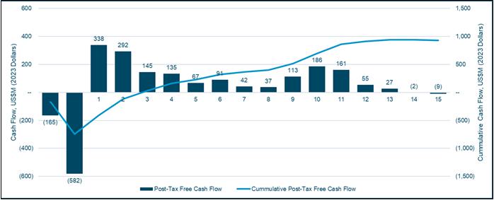
Source: Ausenco, 2023
Figure 22-2 shows a summary of the post-tax sensitivity analysis
results.
As shown in Figure 22-2, the sensitivity revealed that the
Project is most sensitive to changes in commodity price, exchange rate, and less sensitive to initial capital cost and operating costs.
The PFS sensitivity to gold price and discount rate are shown
in Table 22-3 below.
| Courageous Lake Project | Page 336 |
| Pre-feasibility Study and Preliminary Economic Assessment NI 43-101 Technical Report | January 5, 2024 |
| Figure
22-2: | Post-Tax
NPV and IRR Sensitivity Results |
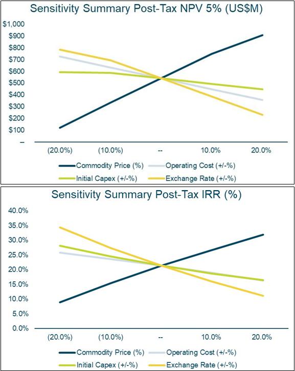
Source: Ausenco, 2023
| Courageous Lake Project | Page 337 |
| Pre-feasibility Study and Preliminary Economic Assessment NI 43-101 Technical Report | January 5, 2024 |
| Table
22-3: | Post-Tax
Sensitivity Summary (Highlighted Values are Base Case Scenario) |
| |
Post-Tax
NPV Sensitivity To Discount Rate |
|
Post-Tax
IRR Sensitivity To Discount Rate |
| |
|
Commodity Price (US$/oz) |
|
|
Commodity Price (US$/oz) |
| Discount Rate |
|
(20.0%) |
(10.0%) |
-- |
10.0% |
20.0% |
Discount Rate |
|
(20.0%) |
(10.0%) |
-- |
10.0% |
20.0% |
| 1.0% |
$279 |
$556 |
$830 |
$1,104 |
$1,376 |
1.0% |
8.2% |
14.7% |
20.6% |
25.9% |
30.9% |
| 3.0% |
$180 |
$423 |
$661 |
$898 |
$1,134 |
3.0% |
8.2% |
14.7% |
20.6% |
25.9% |
30.9% |
| 5.0% |
$99 |
$314 |
$523 |
$730 |
$936 |
5.0% |
8.2% |
14.7% |
20.6% |
25.9% |
30.9% |
| 8.0% |
$5 |
$186 |
$360 |
$531 |
$702 |
8.0% |
8.2% |
14.7% |
20.6% |
25.9% |
30.9% |
| 10.0% |
($44) |
$118 |
$274 |
$426 |
$578 |
10.0% |
8.2% |
14.7% |
20.6% |
25.9% |
30.9% |
| Post-Tax
NPV Sensitivity To Opex |
Post-Tax
IRR Sensitivity To Opex |
| |
|
Commodity Price (US$/oz) |
|
|
Commodity Price (US$/oz) |
| Opex |
|
(20.0%) |
(10.0%) |
-- |
10.0% |
20.0% |
Opex |
|
(20.0%) |
(10.0%) |
-- |
10.0% |
20.0% |
| (20.0%) |
$291 |
$501 |
$708 |
$915 |
$1,046 |
(20.0%) |
13.8% |
19.6% |
24.9% |
29.9% |
34.7% |
| (10.0%) |
$195 |
$407 |
$615 |
$822 |
$981 |
(10.0%) |
11.1% |
17.2% |
22.8% |
27.9% |
32.9% |
| -- |
$99 |
$314 |
$523 |
$730 |
$936 |
-- |
8.2% |
14.7% |
20.6% |
25.9% |
30.9% |
| 10.0% |
($4) |
$218 |
$429 |
$637 |
$844 |
10.0% |
4.9% |
12.0% |
18.2% |
23.8% |
28.9% |
| 20.0% |
($115) |
$122 |
$335 |
$544 |
$751 |
20.0% |
1.0% |
9.0% |
15.6% |
21.5% |
26.9% |
| Post-Tax
NPV Sensitivity To Initial Capex |
Post-Tax
IRR Sensitivity To Initial Capex |
| |
|
Commodity Price (US$/oz) |
|
|
Commodity Price (US$/oz) |
| Initial Capex |
|
(20.0%) |
(10.0%) |
-- |
10.0% |
20.0% |
Initial Capex |
|
(20.0%) |
(10.0%) |
-- |
10.0% |
20.0% |
| (20.0%) |
$200 |
$411 |
$585 |
$745 |
$910 |
(20.0%) |
13.0% |
20.6% |
27.3% |
33.5% |
39.6% |
| (10.0%) |
$150 |
$363 |
$571 |
$778 |
$979 |
(10.0%) |
10.3% |
17.4% |
23.6% |
29.4% |
35.2% |
| -- |
$99 |
$314 |
$523 |
$730 |
$936 |
-- |
8.2% |
14.7% |
20.6% |
25.9% |
30.9% |
| 10.0% |
$49 |
$264 |
$474 |
$682 |
$889 |
10.0% |
6.4% |
12.5% |
17.9% |
23.0% |
27.7% |
| 20.0% |
($6) |
$214 |
$425 |
$634 |
$841 |
20.0% |
4.8% |
10.6% |
15.7% |
20.5% |
24.9% |
| Post-Tax
NPV Sensitivity To Recovery Mill |
Post-Tax
IRR Sensitivity To Recovery Mill |
| |
|
Commodity Price (US$/oz) |
|
|
Commodity Price (US$/oz) |
| Recovery Mill |
|
(20.0%) |
(10.0%) |
-- |
10.0% |
20.0% |
Recovery Mill |
|
(20.0%) |
(10.0%) |
-- |
10.0% |
20.0% |
| (20.0%) |
($329) |
($91) |
$100 |
$272 |
$440 |
(20.0%) |
0.0% |
1.9% |
8.2% |
13.5% |
18.3% |
| (10.0%) |
($92) |
$121 |
$314 |
$502 |
$689 |
(10.0%) |
1.9% |
8.9% |
14.7% |
20.0% |
24.9% |
| -- |
$99 |
$314 |
$523 |
$730 |
$936 |
-- |
8.2% |
14.7% |
20.6% |
25.9% |
30.9% |
| 10.0% |
$271 |
$502 |
$730 |
$957 |
$1,083 |
10.0% |
13.5% |
20.0% |
25.9% |
31.4% |
36.7% |
| 20.0% |
$306 |
$540 |
$772 |
$942 |
$1,119 |
20.0% |
14.6% |
21.1% |
27.1% |
32.7% |
38.1% |
| Post-Tax
NPV Sensitivity To Head Grade |
Post-Tax
IRR Sensitivity To Head Grade |
| |
|
Commodity Price (US$/oz) |
|
|
Commodity Price (US$/oz) |
| Head Grade |
|
(20.0%) |
(10.0%) |
-- |
10.0% |
20.0% |
Head Grade |
|
(20.0%) |
(10.0%) |
-- |
10.0% |
20.0% |
| (20.0%) |
($329) |
($91) |
$100 |
$272 |
$440 |
(20.0%) |
0.0% |
1.9% |
8.2% |
13.5% |
18.3% |
| (10.0%) |
($92) |
$121 |
$314 |
$502 |
$689 |
(10.0%) |
1.9% |
8.9% |
14.7% |
20.0% |
24.9% |
| -- |
$99 |
$314 |
$523 |
$730 |
$936 |
-- |
8.2% |
14.7% |
20.6% |
25.9% |
30.9% |
| 10.0% |
$271 |
$502 |
$730 |
$957 |
$1,083 |
10.0% |
13.5% |
20.0% |
25.9% |
31.4% |
36.7% |
| 20.0% |
$438 |
$688 |
$936 |
$1,083 |
$1,276 |
20.0% |
18.3% |
24.8% |
30.9% |
36.7% |
42.4% |
| Post-Tax
NPV Sensitivity To Exchange Rate |
Post-Tax
IRR Sensitivity To Exchange Rate |
| |
|
Commodity Price (US$/oz) |
|
|
Commodity Price (US$/oz) |
| Exchange Rate |
|
(20.0%) |
(10.0%) |
-- |
10.0% |
20.0% |
Exchange Rate |
|
(20.0%) |
(10.0%) |
-- |
10.0% |
20.0% |
| (20.0%) |
$418 |
$625 |
$777 |
$937 |
$1,098 |
(20.0%) |
20.6% |
27.2% |
33.4% |
39.3% |
45.2% |
| (10.0%) |
$261 |
$470 |
$678 |
$884 |
$1,083 |
(10.0%) |
14.0% |
20.6% |
26.5% |
32.0% |
37.8% |
| -- |
$99 |
$314 |
$523 |
$730 |
$936 |
-- |
8.2% |
14.7% |
20.6% |
25.9% |
30.9% |
| 10.0% |
($81) |
$152 |
$366 |
$575 |
$782 |
10.0% |
2.5% |
9.4% |
15.3% |
20.6% |
25.4% |
| 20.0% |
($293) |
($20) |
$205 |
$418 |
$627 |
20.0% |
0.0% |
4.5% |
10.4% |
15.7% |
20.6% |
| Courageous Lake Project | Page 338 |
| Pre-feasibility Study and Preliminary Economic Assessment NI 43-101 Technical Report | January 5, 2024 |
There are no relevant adjacent properties to the Courageous
Lake Property that are the subject of this Report.
| 24 | OTHER RELEVANT DATA AND INFORMATION |
| 24.1 | 2024 Preliminary Economic Assessment |
The PEA is preliminary in nature
and includes Inferred Mineral Resources considered too speculative geologically to have the economic considerations applied to them that
would enable them to be categorized as Mineral Reserves, and there is no certainty that the results of the PEA will be realized. Mineral
Resources are not Mineral Reserves and do not have demonstrated economic viability.
The PEA is a standalone mine plan
that has been undertaken to evaluate the conceptual expansion of the open pit below the base of the permafrost. The 2024 PEA assumes the
2024 PFS has been completely mined out prior to PEA mining activities. The PEA does not include any Mineral Resources from the Walsh Lake
deposit.
The Mineral Resources used in the
2024 PEA mine plan are exclusive of the pits mined out in the 2024 PFS plan and the associated Mineral Reserves or Mineral Resources inside
of those pits. The 2024 PEA mine plan includes Inferred Resources.
The proposed process plant for the
2024 PEA design has an average process rate of 7,500 t/d and envisages an open pit mining operation planned to operate for 16 years. The
process plant in PEA Year 1 is assumed to be existing from the 2024 PFS (in PFS Year 14).
Mineralized material undergoes crushing,
grinding and flotation to produce a clean sulphide flotation concentrate. The flotation concentrate is contacted with acidic solution
in the acidulation circuit prior to sulphide oxidation in a POX circuit. Oxidized material from the POX circuit is washed and fed to the
cyanide leach circuit. Gold will be recovered from the cyanide leach solution using the Merrill-Crowe process.
| Courageous Lake Project | Page 339 |
| Pre-feasibility Study and Preliminary Economic Assessment NI 43-101 Technical Report | January 5, 2024 |
The 2024 PEA mine site general arrangement
is shown in Figure 24-1.
| Figure
24-1: | Mine
Site General Arrangement |
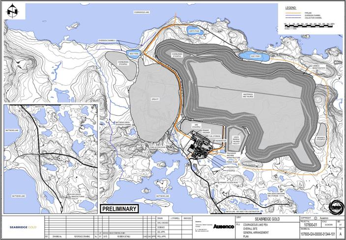
Source: Ausenco, 2023
| 24.1.2.1 | Net Smelter Return Block Model |
The NSR per tonne for each block
in the block model used for the PEA mine planning is determined using the mineral resources discussed in Section 14. It is net of off-site
costs and inclusive of on-site mill recovery. It is used as a cut-off item for break-even mill feed/waste selection, as well as for grade
bins used to optimize cash flow in the open pit production scheduling.
NSR is estimated using net smelter
price (NSP) and process recoveries. A gold price of $1,400 US$/oz is assumed, and the total off-site costs are assumed to be $3.50 US$/oz.
The assumed process recoveries are shown in Table 24-2.
| Courageous Lake Project | Page 340 |
| Pre-feasibility Study and Preliminary Economic Assessment NI 43-101 Technical Report | January 5, 2024 |
| 24.1.3 | Open Pit Mining Method |
The objective of the 2024 PEA open pit
mining study is to develop an open pit mine plan that:
| · | maximizes recovery of the resource |
| · | is economically positive. |
The geotechnical assumptions used
for the PEA pit are shown in Table 24-1 and are based on the PFS pits slope design updated by Tetra Tech (2023b). There have been no pit
slope stability analyses completed for the PEA pit as part of the current study.
| Table
24-1: | Pit
Slope Assumptions |
Slope Design
Element
|
166° to 226° South
to Southwest Wall |
226° to 312° West
Wall and Tundra
Fault |
Wall Sector Azimuth
312° to 012°
Northwest to North
Wall |
012° to 066° North
to Northeast Wall |
066° to 166° East Wall
|
Bench Face
Angle (BFA)
Degrees |
64 |
80 |
64 |
71 |
75 |
Final Bench
Height (m) |
20 |
20 |
20 |
20 |
20 |
Catch Bench
Width (m) |
12 |
10.7 |
12 |
10 |
10 |
Inter-Ramp
Angle (IRA) |
42.6 |
54.6 |
42.6 |
49.8 |
52.5 |
Design
Basis and Limiting Factors |
Inter-ramp
slope instability relating to J3 and J0 interaction. |
Potential bench scale toppling; additional ravelling related to Tundra Shear.
May require single benching and additional catchment; develop ramp in West Wall where possible. may require. |
Design
controlled by inter-ramp slope instability relating to J1 and J0 interaction. |
Bench
face angle controlled by J4; inter- ramp slope instability on J4/J0. |
Bench
face angle controlled by foliation orientation; additional ravelling related to Tundra Shear; additional catchment and single benching
may be required locally. |
| Courageous Lake Project | Page 341 |
| Pre-feasibility Study and Preliminary Economic Assessment NI 43-101 Technical Report | January 5, 2024 |
Slope Design
Element
|
166°
to 226° South
to Southwest Wall |
226° to 312° West
Wall and Tundra
Fault |
Wall Sector Azimuth
312° to 012°
Northwest to North
Wall |
012°
to 066° North
to Northeast Wall |
066° to 166° East Wall
|
Comments
and
Slope
Depressurization
Requirements |
Slope
depressurization required.
Assumes 5% rock bridge along
joint surfaces.
Potential for steepening overall slope angle. |
No
depressurization required.
Does not require rock bridging to meet DAC. |
Slope depressurization required.
Assumes 5% rock bridge along
joint surfaces.
|
No depressurization required.
Does not require rock bridging to meet DAC. |
Slope
depressurization required.
Does not require rock bridging to meet DAC.
Incorporate a 30 m-wide geotechnical step-out at mid-point of the wall to decouple the slope as is current industry practice.
|
| 24.1.3.1 | Pit Optimization Method |
The economic pit limit is selected after evaluating Lerch
Grossman (LG) pit cases. Inputs to the LG pit limit assessment shown in Table 24-2.
| Table
24-2: | LG
Pit Limit Primary Assumptions (CAD$) |
| Assumption |
Value |
| Mining Cost - Waste |
C$2.75/t |
| Mining Cost - Mill feed |
C$3.75/t |
| Process, G&A, Site Services |
C$49.66/t |
| |
<0.3 g/t |
0% |
| |
0.3 g/t - 0.5 g/t |
40% |
| |
0.5 g/t - 0.75 g/t |
65% |
| Process Au Recoveries |
0.75 g/t - 3.0 g/t |
76%
- 92%1 |
| |
3.0 g/t - 5.0 g/t |
93% |
| |
5.0 g/t - 8.0 g/t |
94% |
| |
>8.0 g/t |
96% |
| Pit Slope Angle |
See Table 24-1 |
| Metal Prices |
$1,400 US$/oz |
Note:
| 1. | Between 0.75 and 3.0 g/t, Recovery = -0.1423 x AU5 + 0.2604
x AU4 + 5.593 x AU3 - 30.217 x AU2 + 60.566 x AU + 44.935 |
| Courageous Lake Project | Page 342 |
| Pre-feasibility Study and Preliminary Economic Assessment NI 43-101 Technical Report | January 5, 2024 |
The 2024 PEA LG pits are generated
by varying prices in the range from 30% to 150% of the base NSR. Note the tonnes and grades for each LG pit shell are based on the same
cut-off grade as the 100% case, therefore the above different price cases cannot be considered a price sensitivity. The PEA LG’s
are not restricted to the permafrost boundary and uses the PFS mined-out surface for initial topography. Figure 24-2 shows the resulting
mill feed sensitivity to price case. The 70% price case is selected as the ultimate pit for detailed designs.
| Figure
24-2: | Sensitivity
of 2024 PEA Mill Feed Tonnes to Price Case |
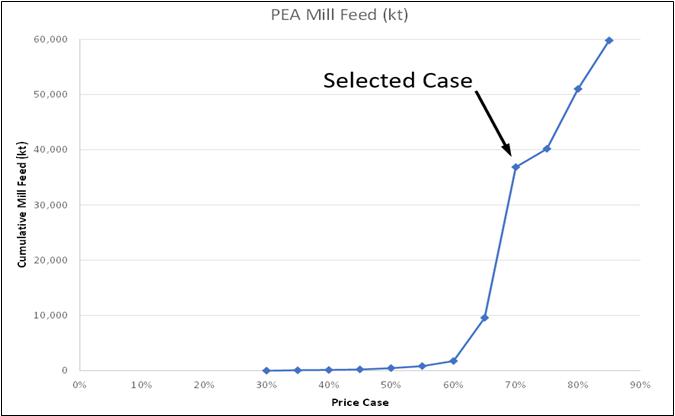
Source: MMTS, 2023
| Courageous Lake Project | Page 343 |
| Pre-feasibility Study and Preliminary Economic Assessment NI 43-101 Technical Report | January 5, 2024 |
| 24.1.3.3 | Mining Loss and Dilution |
Mining loss and dilution is estimated
using an edge count method. Each block is examined and the number of contact edges for mill feed and waste are determined. Mill feed blocks
that have three or four waste contact edges are treated as waste (mining loss) while waste blocks that have three or four contact edges
are treated as mill feed (mining dilution). The summarized loss and dilution parameters are shown in Table 24-3:
| Table
24-3: | PEA
Mining Losses and Dilution |
| Description |
Tonnes
(kt) |
Tonnes
(%) |
Au Grade
(g/t) |
| Losses |
5,805 |
12% |
1.93 |
| Dilution |
752 |
2% |
0.83 |
The open pit development is designed
as a conventional truck-shovel operation with 227-t autonomous trucks with 16 m3 and 12 m3 shovels. The mine design
includes two nested pit phases to balance stripping requirements while satisfying the process plant requirements.
The design parameters include:
| · | maximum road grades of 10% |
| · | safety bench interval of 20 m |
| · | variable slope angles by sector. |
A minimum mining width between pit
phases is allocated to maintain a suitable mining platform for efficient mining operations. This is established based on equipment size
and operating characteristics. For this study, the minimum mining width generally conforms to 50 m, which provides sufficient room for
two-sided truck loading, but where phases merge, it is sometimes less.
Phase 5 and Phase 6 are concentric
phases around the mined-out PFS pit. Phase 5 accelerates some mill feed and defers waste stripping. Phase 6 is the Ultimate Pit. Figure
24-4 shows the 2024 PEA phases. Figure 24-4 shows the mill feed and waste tonnes, grade and strip ratio by phase.
An East-West section view of the PEA phases with the PFS
mined out is shown in Figure 24-3.
| Courageous Lake Project | Page 344 |
| Pre-feasibility Study and Preliminary Economic Assessment NI 43-101 Technical Report | January 5, 2024 |
| Figure
24-3: | Courageous
Lake PEA Pit Limit – East-West Section at North 7109735 |
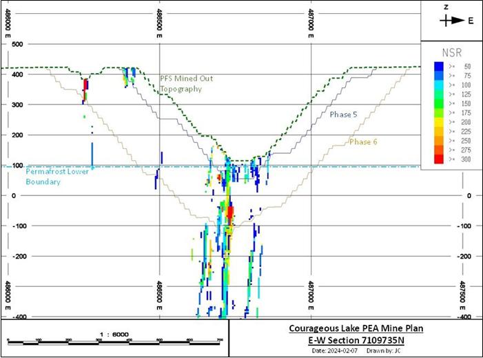
Source: MMTS, 2024
| Courageous Lake Project | Page 345 |
| Pre-feasibility Study and Preliminary Economic Assessment NI 43-101 Technical Report | January 5, 2024 |
| Figure
24-4: | Pit
Design – Plan View |
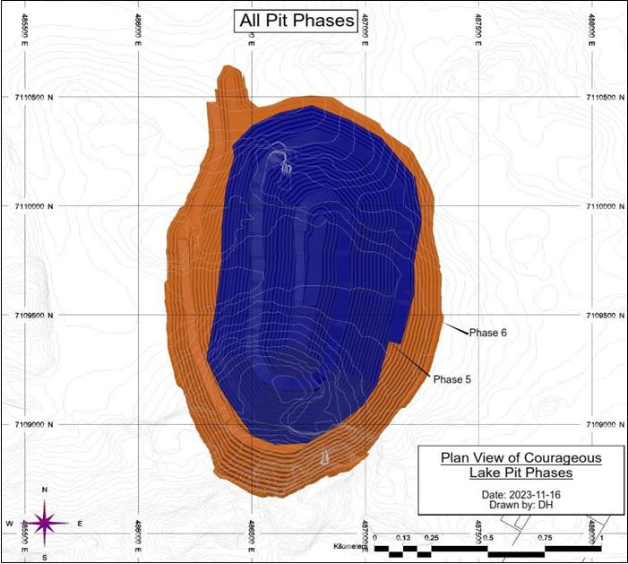
Source: MMTS, 2023
| Courageous Lake Project | Page 346 |
| Pre-feasibility Study and Preliminary Economic Assessment NI 43-101 Technical Report | January 5, 2024 |
| Table
24-4: | Phase
Strip Ratio |
| |
Ore |
Waste |
Total
Material |
| |
kTonnes |
Au |
kTonnes |
kTonnes |
Strip
Ratio |
| Phase 5 |
10,883 |
2.44 |
197,797 |
208,681 |
18.2 |
| Phase 6 |
32,577 |
2.68 |
521,384 |
553,961 |
16.0 |
| Grand Total |
43,460 |
2.62 |
719,181 |
762,641 |
16.5 |
Phase design by MMTS for the pit
has been carried out in an iterative process following TetraTech’s PFS pit wall parameters, described in Section 16.14.
| 24.1.3.5 | Pit Resource Estimate |
The pit delineated resources summarized
in Table 24-5 are a subset of the mineral resources and quantities that are included in Section 14. The pit delineated resources use an
NSR cut-off grade of C$49.66/t and accounts for losses and dilution.
| Table
24-5: | Pit
Delineated Resource |
| Category |
Mill
Feed |
Diluted
Grades |
Contained
Metal |
| |
(Mt) |
Au
(g/t) |
Au
(Moz) |
| Measured |
2.71 |
2.8 |
0.2 |
| Indicated |
38.08 |
2.6 |
3.1 |
| Measured + Indicated |
40.78 |
2.6 |
3.4 |
| Inferred |
4.68 |
3.3 |
0.3 |
The PEA is preliminary in nature
and includes Inferred Mineral Resources considered too speculative geologically to have the economic considerations applied to them that
would enable them to be categorized as Mineral Reserves, and there is no certainty that the results of the PEA will be realized. Mineral
Resources are not Mineral Reserves and do not have demonstrated economic viability.
| 24.1.3.6 | Waste Rock Facilities |
All open pit waste is placed onto the CPSF.
The CPSF uses two construction methods to
support the tailings paddock system construction. The CPSF is created bottom up in lifts that alternate between 10 and 13 m in
height. The paddocks are contained within the 13 m lifts, while the 10 m lifts placed between the paddock lifts are completely waste
material. Waste not required for construction of tailings paddocks is placed directly by the haul fleet with support from dozers as
required. Waste needed to create tailings paddocks is delivered by the haul fleet to the CPSF and then stockpiled for later
placement as described in Section 18. When waste is used to cover a completed tailings paddock the haul trucks will dump short of
the berm and dozers will push the material on top of the completed tailings paddock. The CPSF is constrained to above the PFS CPSF
and the east catchment. It has a maximum elevation of 546 m. Table 24-5 shows the CPSF.
| Courageous Lake Project | Page 347 |
| Pre-feasibility Study and Preliminary Economic Assessment NI 43-101 Technical Report | January 5, 2024 |
| Figure
24-5: | 2024
PEA Co-Placement Storage Facility Design |
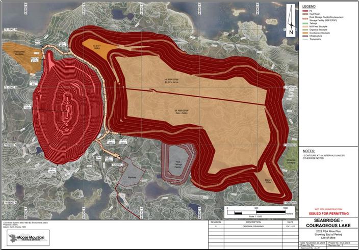
Source: MMTS, 2023
Prior to mine development, overburden is salvaged from the
footprint area where the material is considered as soil, suitable for reclamation purposes.
| Courageous Lake Project | Page 348 |
| Pre-feasibility Study and Preliminary Economic Assessment NI 43-101 Technical Report | January 5, 2024 |
| 24.1.3.7 | Production Scheduling (Open Pit) |
| 24.1.3.7.1 | Open Pit Major Equipment Selection |
The mine load and haul fleet will
use diesel hydraulic excavators (22 m3 bucket for waste and 12 m3 for mill feed) matched with autonomous 227-t trucks.
Smaller excavators are used for mill feed to increase the mining selectivity and therefore mill feed recovery; these unit sizes are proven
in operating mines around the world. All equipment is diesel powered.
Suitable drill sizes (228 mm hole
size) are selected to match the size of truck/shovel equipment. Diesel hydraulic percussive drills with a hole size of 6.5 inches (165
mm) will be used for controlled blasting techniques on high wall rows.
| 24.1.3.7.2 | Schedule Criteria |
Scheduling has been carried out
with the MinePlan Schedule Optimizer (MPSO) with the primary program objective to maximize NPV. Schedule optimization is guided by estimated
operating and capital costs, process recoveries, and metal prices. Mill feed from all open pits will be dumped into the primary crusher
or the stockpile depending on mill feed requirements and grade.
| 24.1.3.8 | Open Pit Mine Operations |
Courageous Lake open pit mining
operations will employ bulk mining methods and large capacity equipment. A powder factor of 0.35 kg/t is assumed for the 2024 PEA.
Pit maintenance services include
haul road maintenance, open pit mine dewatering, transporting operating supplies, relocating equipment, and snow removal. Haul road maintenance
is paramount to low haulage costs; dozer and grader hours have been allocated to maintain the haul road network throughout the LOM production
schedule. A rock crusher for road grading material is included.
| 24.1.3.10 | Open Pit Mine Equipment |
Major, support, and ancillary equipment
were costed for the 2024 PEA. The peak major mining equipment is six 22 m3 excavators, one 12 m3 excavator, two
18 m3 wheel loader and a fleet of 37 trucks.
| 24.1.3.11 | Open Pit Dewatering Systems |
The dewatering activities will include
vertical dewatering wells, as well as in-pit sumps.
Brine encountered after Year 6
will be collected and stored in an external location. After Year 13, when pit mining is completed, brine will be stored in the mined-out
pit.
| Courageous Lake Project | Page 349 |
| Pre-feasibility Study and Preliminary Economic Assessment NI 43-101 Technical Report | January 5, 2024 |
| 24.1.3.12 | Open Pit Ancillary Facilities |
The recommended shop sizing for
the open pit operations includes three service bays, one welding bay, and one wash bay. This will accommodate the fleet for the LOM PEA
production plan. The mine maintenance facility will also include a machine shop area, tool storage area, mine muster area, warehouse,
and office complex. A separate tire bay facility will be required to accommodate a truck and a tire manipulator.
| 24.1.3.13 | Pit Slope Design |
Standard truck and shovel equipment
will be used to mine the pit. The pit slope design study update is based on 10 m high operational benches with final bench heights of
20 m in rock. It is understood that a fleet of 227-t trucks will be loaded with waste by excavators, and that smaller more selective loaders
will be used to move mineralized material.
The overburden and open pit slope
design criteria are based on the 2023 updated PFS pit slope design study by Tetra Tech Canada Inc (Tetra Tech 2023b). The overburden soils
will require stripping in the footprint area of the pit. The overburden is ice-rich and susceptible to thaw induced displacement. A thermal
cover will be required to maintain the soil in a frozen state. The pit area’s geology and structure are relatively simple and inclined
at steep angles to the west and parallel to the dominant west dipping foliation structure. The general rock mass quality is ‘Good’
to ‘Very Good’ and the rock is classified as ‘Strong to Very Strong’ and, in some cases, ‘Extremely Strong’.
There have been no slope stability
analyses completed for the PEA pit as part of the current study. WSP completed a preliminary assessment of depressurization requirements
for the PEA Pit (WSP 2023b). The PEA pit will extend 565 m below ground surface. The base of permafrost is undulating, with an average
depth estimate of 335 m below ground surface. The upper portion of the pit slopes will be excavated within permafrost. It is assumed that
within permafrost groundwater pressures are negligible; however, groundwater inflows to the pit are expected to increase as the base of
permafrost is approached through the basal cryopeg, and that a dewatering network will be operational before the PEA pit drops below the
top of the cryopeg beginning in Year 7. Based on a preliminary hydrogeological model a depressurization system consisting of 32 vertical
wells 350-m long and drilled to a depth of 300 m below the top of the basal cryopeg, or 50 m below the ultimate base of the pit will be
required (WSP 2023b). The wells would be installed from an interior bench of the PEA open pit 50 m above the top of the cryopeg.
| 24.1.3.14 | Mine Production Schedule |
The 2024 PEA mine production schedule
is matched to the throughput of the 7.5 kt/d mill with one year of pre-production mining, followed by 16 years of mill feed operations.
End of period maps for the production schedule are shown below.
| Courageous Lake Project | Page 350 |
| Pre-feasibility Study and Preliminary Economic Assessment NI 43-101 Technical Report | January 5, 2024 |
| Figure
24-6: | End
of Period Map Year -1 of PEA |
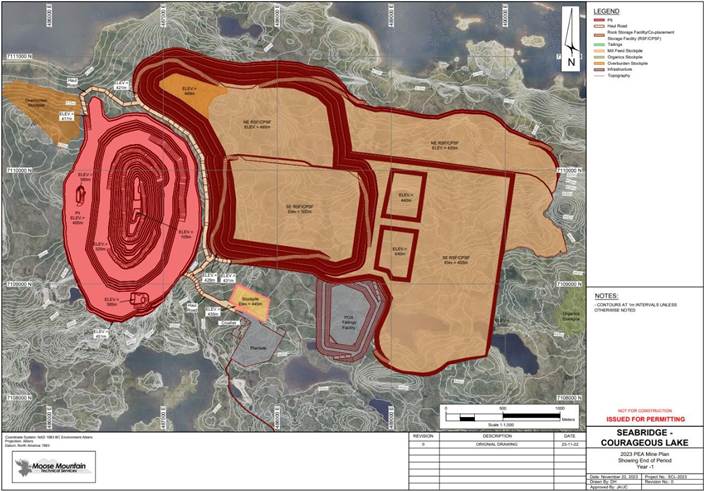
Source: MMTS, 2023
| Courageous Lake Project | Page 351 |
| Pre-feasibility Study and Preliminary Economic Assessment NI 43-101 Technical Report | January 5, 2024 |
| Figure
24-7: | End
of Period Map Year 10 of PEA |
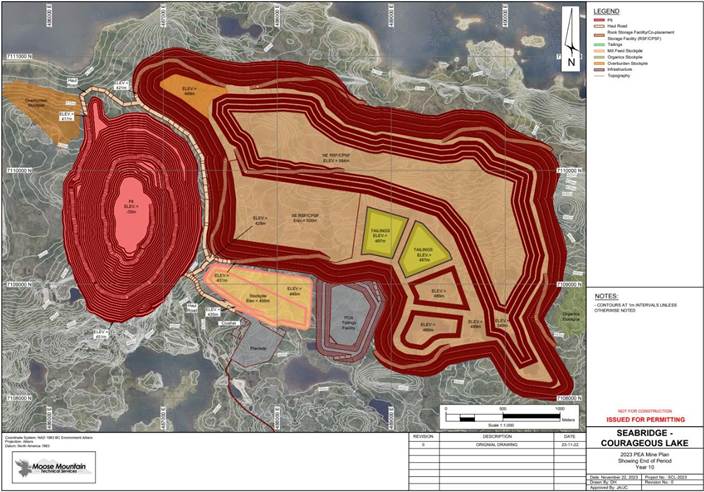
Source: MMTS, 2023
| Courageous Lake Project | Page 352 |
| Pre-feasibility Study and Preliminary Economic Assessment NI 43-101 Technical Report | January 5, 2024 |
| Figure
24-8: | End
of Period Map End of PEA LOM |

Source: MMTS, 2023
The summarized production schedule results are shown in Table 24-6 and
Figure 24-6.
| Courageous Lake Project | Page 353 |
| Pre-feasibility Study and Preliminary Economic Assessment NI 43-101 Technical Report | January 5, 2024 |
| Table
24-6: | Summarized
2024 PEA Production Schedule |
| Year |
|
-1 |
1 |
2 |
3 |
4 |
5 |
6 |
7 |
8 |
9 |
10 |
11 |
12 |
13 |
14 |
15 |
16 |
LOM |
| Pit to Mill |
Amount |
Mt |
- |
1.64 |
2.74 |
1.64 |
1.16 |
0.69 |
1.57 |
2.74 |
2.74 |
1.41 |
1.84 |
1.88 |
1.97 |
0.56 |
0.00 |
0.00 |
0.00 |
22.58 |
| Au |
g/t |
- |
2.22 |
3.92 |
3.86 |
2.33 |
2.85 |
3.37 |
3.70 |
4.07 |
3.34 |
3.62 |
3.65 |
3.78 |
3.91 |
0.00 |
0.00 |
0.00 |
3.53 |
| Pit to Stockpile |
Amount |
Mt |
1.19 |
0.33 |
4.40 |
1.45 |
0.00 |
0.00 |
0.00 |
3.10 |
6.50 |
1.01 |
1.22 |
0.86 |
0.77 |
0.06 |
0.00 |
0.00 |
0.00 |
20.88 |
| Stockpile
Reclaim |
Amount |
Mt |
- |
1.10 |
0.00 |
1.10 |
1.58 |
2.05 |
1.17 |
0.00 |
0.00 |
1.33 |
0.90 |
0.86 |
0.77 |
2.18 |
2.74 |
2.74 |
2.36 |
20.88 |
| Au |
g/t |
- |
2.96 |
0.00 |
2.28 |
1.73 |
1.34 |
1.07 |
0.00 |
0.00 |
2.33 |
2.31 |
2.03 |
1.83 |
1.66 |
1.43 |
1.22 |
0.97 |
1.63 |
| Stockpile Balance |
Amount |
Mt |
1.19 |
0.41 |
4.81 |
5.16 |
3.58 |
1.54 |
0.37 |
3.47 |
9.96 |
9.64 |
9.96 |
9.96 |
9.96 |
7.84 |
5.10 |
2.36 |
0.00 |
0.00 |
| Total
Mill Feed |
Amount |
Mt |
- |
2.74 |
2.74 |
2.74 |
2.74 |
2.74 |
2.74 |
2.74 |
2.74 |
2.74 |
2.74 |
2.74 |
2.74 |
2.74 |
2.74 |
2.74 |
2.36 |
43.46 |
| Au |
g/t |
- |
2.52 |
3.92 |
3.23 |
1.99 |
1.72 |
2.39 |
3.70 |
4.07 |
2.85 |
3.19 |
3.14 |
3.23 |
2.12 |
1.43 |
1.22 |
0.97 |
2.62 |
| Metal to the Mill |
Au |
Moz |
- |
0.22 |
0.35 |
0.28 |
0.17 |
0.15 |
0.21 |
0.33 |
0.36 |
0.25 |
0.28 |
0.28 |
0.28 |
0.19 |
0.13 |
0.11 |
0.07 |
3.66 |
| Waste Mined (excluding rehandle) |
Amount |
Mt |
98.81 |
96.93 |
92.86 |
95.81 |
79.76 |
70.26 |
61.26 |
62.16 |
36.04 |
7.80 |
7.36 |
5.17 |
4.07 |
0.87 |
0.00 |
0.00 |
0.00 |
719.18 |
| Total Material Mined |
Amount |
Mt |
100.00 |
98.90 |
100.00 |
98.90 |
80.92 |
70.95 |
62.83 |
68.00 |
45.28 |
10.22 |
10.42 |
7.91 |
6.81 |
1.49 |
0.00 |
0.00 |
0.00 |
762.64 |
| Total Material Moved |
Amount |
Mt |
100.00 |
100.00 |
100.00 |
100.00 |
82.50 |
73.00 |
64.00 |
68.00 |
45.28 |
11.55 |
11.32 |
8.77 |
7.59 |
3.67 |
2.74 |
2.74 |
2.36 |
783.52 |
Notes:
| 1. | There is no planned rehandle in the waste mined in the production schedule |
| 2. | Mill feed includes Inferred Mineral Resources that are exclusive of the 2024 PFS.
Inferred Mineral Resources are considered too speculative geologically to have the economic considerations applied to them that would
enable them to be categorized as Mineral Reserves. There is no certainty that the results of the PEA will be realized. Mineral Resources
that are not Mineral Reserves do not have demonstrated economic viability |
| 3. | Exclusive of material mined in PFS as described in Section 16 |
| Courageous Lake Project | Page 354 |
| Pre-feasibility Study and Preliminary Economic Assessment NI 43-101 Technical Report | January 5, 2024 |
| Figure
24-9: | Courageous
Lake PEA Mill Feed Production Schedule |
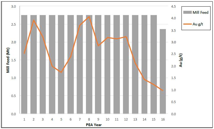
Source: MMTS, 2023
Process flowsheet for Courageous
Lake project was selected based on the preliminary metallurgical testwork results summarized in Section 13 and subsequent economic modelling.
The majority of the unit operations selected to build the plant flowsheet are standard technologies widely used in gold processing plants.
The plant is designed for a throughput
of 7,500 t/d with availability of 90%. The crusher plant circuit design is set at 65% availability and the gold room availability is set
at 52 weeks/a.
Based on the available information, metallurgical
test work performed on various samples provides a reasonable indication of the mineralogical and metallurgical performance characteristics
of the materials for the Courageous Lake PEA. The process flowsheet developed for the Courageous Lake mineralization is considered appropriate
for the current 2024 PEA given the nature of the mill feed and similar metallurgical performance of the samples from the Courageous Lake
deposits.
| Courageous Lake Project | Page 355 |
| Pre-feasibility Study and Preliminary Economic Assessment NI 43-101 Technical Report | January 5, 2024 |
The results of the comminution
tests indicate that the material is very competent with respect to breakage in a SAG mill and of moderate hardness with respect to grinding
in a ball mill.
The test work results indicated
that the material responded well to flotation concentration. The results from POX and cyanidation tests indicated that Courageous Lake
concentrates were amendable to high temperature POX with a significant improvement in gold extraction and high sulfur oxidation. The test
work indicated that gold extraction improved substantially with increasing sulfur oxidation.
Process plant from the 2024 PFS
mine site is used for the purposes of this PEA from PEA Year 1. The selected flowsheet includes a three-stage crushing circuit followed
by a grinding circuit consisting of a ball mill circuit operating in closed circuit with a cyclone cluster. Classified material reports
to a flotation circuit consisting of rougher and cleaner flotation circuits. The cleaner concentrate is reground in a ball mill operating
in closed circuit with a cyclone cluster prior to advancing to the concentrate pre-treatment circuit. Cleaner tailings combine with rougher
tailings for thickening before being discharged to a TSF. Overflow from regrind cyclones is thickened and undergoes acidulation to break
down the carbonates prior to being thickened and entering the POX circuit. The oxidized concentrate is leached and then washed in six-stages
through a CCD circuit. The resulting pregnant solution will be processed using a Merrill-Crowe treatment by adding zinc powder to precipitate
gold and silver. The precious metals precipitate will be smelted on site to produce gold-silver doré bars.
An overall process flow diagram is presented
in Figure 24-10.
| Courageous Lake Project | Page 356 |
| Pre-feasibility Study and Preliminary Economic Assessment NI 43-101 Technical Report | January 5, 2024 |
| Figure
24-10: | Process
Flowsheet |
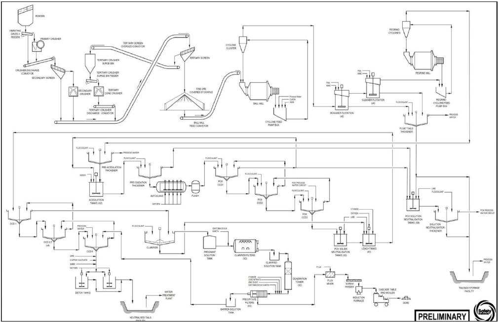
Source: Ausenco, 2023
ROM material is hauled from the
mine and stockpiled or directly tipped into to the ROM feed hopper. Material from the hopper is discharged by gravity to a vibrating grizzly
screen where oversize is discharged into the primary jaw crusher. This oversize material is crushed by the primary jaw crusher, a modular
rock breaker is available to manage large rocks that may exceed the crusher cavity size.
The primary crusher discharge
and vibrating grizzly undersize is transferred to the secondary screen by the crusher discharge conveyor. Screen oversize material
is gravity fed into the secondary cone crusher. Crusher discharge and secondary screen undersize is conveyed to the tertiary screen.
Tertiary crusher discharge combined with secondary screen undersize material and secondary crusher product is transferred to the
tertiary screen by the same conveyor. Oversize from the tertiary screen is conveyed to the tertiary crusher surge bin which ensures
the crusher is choke fed. Material that passes through the tertiary screen discharges onto the fine material transfer conveyor which
will deliver material to the stockpile. The material crushed by the tertiary crusher is reduced to an 80% passing product size (P80)
of 9 mm at the screen undersize.
| Courageous Lake Project | Page 357 |
| Pre-feasibility Study and Preliminary Economic Assessment NI 43-101 Technical Report | January 5, 2024 |
| 24.1.4.1.3 | Primary Grinding and Classification |
Fine material from the stockpile
is transferred onto the ball mill feed conveyor which feeds the ball mill. The circuit is sized based on a grinding circuit feed size
(F80) of 9 mm and a circuit product size (P80) of 106 µm. The ball mill product slurry will discharge onto a rubber-lined trommel
screen with trommel undersize reporting into the cyclone feed pumpbox, where the material is pumped to the cyclone cluster. Promoter and
copper sulphate are added to the cyclone feed pumpbox to activate gold bearing sulphides for downstream flotation. Cyclone overflow reports
to the flotation circuit.
The overflow from the primary cyclone
reports to the rougher cell feed box. In this circuit, various reagents are employed to enhance the selectivity of the flotation process.
The rougher concentrate is collected from each rougher cell and pumped to cleaner flotation, while rougher tailings combine with cleaner
tailings. Combined float tailings will be thickened to 65% solids. Portion of the flotation tailings thickener underflow will be used
for neutralizing the acidic solution generated from the POX process. The rest of the underflow slurry will combine with POX solution neutralization
thickener underflow prior to being discharged to the CPSF.
The rougher flotation concentrate
will be further upgraded in cleaner flotation circuit. The cleaner concentrate is pumped to regrind cyclone feed box. The regrind circuit
consists of a cyclone cluster and a regrind ball mill operating in closed circuit. The overflow target product size is 43 µm. The
cyclone overflow reports to the pre-acidulation thickener, while the underflow flows back to the regrind mill.
| 24.1.4.1.5 | Concentrate Acidulation |
Pre-acidulation thickener underflow
slurry, at 50% w/w solids, is pumped to two agitated acidulation tanks operating at 50°C. The concentrate will be contacted with a
portion of the acidic POX CCD overflow solution and fresh sulfuric acid solution. Sulfuric acid reacts with the carbonates to form gypsum
and carbon dioxide which reduces the generation of carbon dioxide in the autoclaves and thereby improves the utilization of oxygen. The
acidulated slurry is pumped to pre-oxidation thickener where it is thickened to 50% w/w solids prior to POX stage.
| 24.1.4.1.6 | Pressure Oxidation and Counter Current Decantation |
The autoclave vessel consists
of four compartments and five agitators and is operated at overall pressure of 2,150 kPa and 200°C. Oxygen is supplied via
sparging system at partial pressure of 690 kPa. The oxidation of sulphides in the slurry occurs autogenously once started and water
is added to autoclave as required to control the reaction temperature. The autoclave vessel is designed to provide residence time of
90 minutes. The oxidized slurry and the vent gases discharge into a flash vessel where water is flashed to steam as the pressure is
reduced to atmospheric. The flash vessel is equipped with a gas scrubber to control steam and acidic emissions. The flash vessel
slurry is sent to the POX CCD to wash the acid out of the solids.
| Courageous Lake Project | Page 358 |
| Pre-feasibility Study and Preliminary Economic Assessment NI 43-101 Technical Report | January 5, 2024 |
Oxidized slurry passes through
a three-stage CCD circuit, where gold containing solids are washed with process water to reduce slurry acidity. A portion of the acidic
solution from the thickener overflow will be recycled to the pre-acidulation circuit, while the rest of the solution from the thickener
overflow will be sent to a subsequent acidic solution neutralization circuit.
The underflow of the third stage of the POX
CCD circuit will be pumped to an agitated tank where lime will be added to neutralize the slurry and increase the slurry pH to 10.5-11
prior to leaching stage.
Remaining portion of the acidic wash
water from POX CCD circuit will be neutralized in with a fraction of the flotation tailings acting as neutralizing agents and trimmed
with lime. The neutralization tanks are sized to provide residence time of 80 minutes. The treated slurry with target pH of 8.5 will be
pumped to flotation tailings pumpbox for discharge to the CPSF.
Neutralized POX CCD underflow slurry
is pumped into the agitated leaching tanks with oxygen sparged to each tank to maintain the target dissolved oxygen levels. Lime is added
to maintain pH to the desired set point. Cyanide solution is added to the first leach tank. The leach circuit is sized to provide total
residence time of 12 hours. The leached slurry from the last leaching tank will be washed using in a CCD and the pregnant solution will
be treated using a Merrill-Crowe process.
| 24.1.4.1.9 | Counter Current Decantation |
A six-stage CCD circuit will be
used to wash the dissolved precious metals from the leached solids. The underflow of the last CCD thickener will be pumped to a cyanide
destruction circuit prior to disposal. The barren solution from the Merrill-Crowe circuit and fresh water will be used as a washing solution.
The overflow from the first CCD thickener will be collected in the pregnant solution tank and sent to the Merrill-Crowe process.
| 24.1.4.1.10 | Merrill-Crowe Precipitation Circuit and Refining Circuit |
The pregnant solution from the
CCD washing circuit will be treated using the Merrill-Crowe process to recover the contained precious metals by zinc-dust cementation.
The pregnant solution will be clarified and de-aerated prior to mixing with zinc dust, lead nitrate, and cyanide in the precipitate mixing
tank where the precipitation reactions occur. The slurry with the gold and silver precipitates will be pumped through a filter press where
the gold and silver precipitates will be recovered.
Gold and silver precipitates
from the Merrill-Crowe circuit will be treated by smelting into gold-silver doré bars. The refining process will be performed
in a batch mode. Gold-silver doré products will be stored in a dedicated safe in the gold room. Sufficient ventilation, fume
hoods and fans, and off-gas handling will be installed in the gold room for a healthy work environment.
| Courageous Lake Project | Page 359 |
| Pre-feasibility Study and Preliminary Economic Assessment NI 43-101 Technical Report | January 5, 2024 |
| 24.1.4.1.11 | Cyanide Destruction and Neutralized Tailings |
Cyanide detoxification will take
place using the SO2/air process. In this process sodium metabisulphite will be used as the SO2 source, copper sulphate is used as a catalyst
and lime is used to maintain the pH of the reaction. The washed leach residue slurry from the CCD washing circuit will be treated in the
cyanide detoxification circuit consisting of two tanks in parallel that were sized for a total residence time of 90 minutes. This process
will reduce the WAD cyanide in the tailings to less than 25 mg/L before being discharged to the LRTF.
| 24.1.4.1.12 | Reagents Handling and Storage |
All the reagents that will be transported
to the site via the winter road during February and March each year. On-site storage will be provided for 12 months.
All the reagents will be prepared
in a dedicated reagent preparation and storage facility within a containment area. Liquid reagents will be added in the undiluted form
via dosing pumps. Solid reagents will be prepared into adequate strength solutions in dedicated mixing tanks and stored in holding tanks
to be added to the processes via dosing pumps. Oxygen required for POX in autoclave, leaching and cyanide destruction will be generated
on site. Annual reagent consumption rates are summarized in the Table 24-7.
| Table
24-7: | Reagents
Consumption |
| Item |
Unit |
Value |
| Diatomaceous Earth |
t/a |
20 |
| Lime (quicklime) |
t/a |
6646 |
| Sodium Cyanide |
t/a |
63 |
| Sulfuric Acid |
t/a |
1 |
| Flocculant |
t/a |
103 |
| MIBC |
t/a |
29 |
| PAX |
t/a |
65 |
| R208 |
t/a |
20 |
| CuSO4 |
t/a |
274 |
| Fluorspar |
t/a |
5 |
| Borax |
t/a |
9 |
| Silica |
t/a |
5 |
| Nitre |
t/a |
1 |
| SMBS |
t/a |
640 |
| Zinc Dust |
t/a |
14 |
| Lead Nitrate |
t/a |
3 |
| Courageous Lake Project | Page 360 |
| Pre-feasibility Study and Preliminary Economic Assessment NI 43-101 Technical Report | January 5, 2024 |
| Item |
Unit |
Value |
| Grinding Media |
t/a |
2,466 |
| Diesel Engine Oil (15W-40) |
t/a |
1,299 |
| 24.1.4.1.13 | Plant Services |
Process water is recovered from
the CPSF into the process water tank and distributed around the plant from the process water tank. The POX circuit has a dedicated water
circuit which is used for POX CCD wash water.
Raw water will be pumped from the
Courageous Lake into the raw water tank and distributed by pumps for various application points, including reagent preparation, gland
seal, autoclave cooling and general mill makeup water supply. Potable water is produced by an on-site potable water plant which processes
water from the raw water tank and makes it fit for consumption and human use. Plant raw water demand is estimated to be 40 m3/h.
Make up water demand for the process plant is estimated to be 207 m3/h.
Plant air service systems will supply
blower air to flotation and leaching circuits, and high-pressure air to general plant and instrumentation services.
The total installed power for the
process plant and estimated annual power consumption is given in Section 17. The total estimated power requirement for the process plant
is 138,156 MWh/a.
| 24.1.5 | Project Infrastructure |
| 24.1.5.1 | Facilities and Services |
Existing facilities, buildings and
services from the 2024 PFS mine site are used for the purposes of this PEA beginning in PEA Year 1, namely:
| · | mining facilities including the mine office
and dry, truck shop, tire change facility, truck wash, explosives storage and manufacturing facility, diesel fuel storage and distribution,
and stockpile |
| · | processing facilities including the primary,
secondary and tertiary crushing, fine material stockpile and reclaim conveyors, process plant, office and laboratory, plant maintenance
building |
| · | mine waste and water management infrastructure
including: tailings facility, tailings distribution system, water reclaim system, downstream water management ponds, and overburden stockpiles |
| · | general facilities including
the camp, gatehouse, emergency response/ambulance bay, warehouse, reagent cold storage, administration building, communications, emergency
power diesel storage, raw, process and potable water storage and distribution, power plant, site sewage system, and solid waste treatment |
| · | site access roads, airstrip and haul roads. |
| Courageous Lake Project | Page 361 |
| Pre-feasibility Study and Preliminary Economic Assessment NI 43-101 Technical Report | January 5, 2024 |
Additional infrastructure required from PEA Year 1 includes:
| ● | three No. 15,000,000 L diesel storages tanks |
| ● | accommodation camp for mining operations |
| ● | water treatment plant for saline groundwater. |
| 24.1.5.2 | Co-placement Storage Facility and Leach Residue Tailings Facility |
The PEA solids management consists
of the containment and long-term management of waste products developed during the LOM operations that consist of waste rock and tailings.
Waste rock developed during the mining of economical mineralized material will be directly hauled to the CPSF along with slurry flotation
tailings storage. For the PEA, Ausenco in conjunction with MMTS developed a CPSF strategy, which uses a paddock system to store tailings
utilizing waste rock to create cells for the tailings storage. The PEA concept assumes that most of the waste rock (90%) would be mined
out of the open pit by the end of PEA Year 7, which may leave insufficient quantities of waste rock for the concurrent construction of
paddock cells for Years 8 through 16. The current mitigation measure, is to develop the cells for year 8 and through 16 prior to years
7 and stockpile material for the final construction of the last cells in the last couple of years. A LRTF will be a fully lined ring dike
with downstream raises to contain the tailings. Both facilities are located just east of the open pit.
| 24.1.5.2.1 | Design
Criteria |
The key design criteria for the CPSF and LRTF are
as follows:
| 24.1.5.2.1.1 | Production
Schedule |
The average flotation tailings
produced will be 7,241 t/d for a 12-year LOM of 29.7 Mt and the average neutralized tailings produced will be 265 t/d for a total LOM
of 1.1M (Refer to Table 24-8).
| Table 24-8: | Production Schedule |
| Production
Year |
Flotation
Tailings (kt) |
Neutralized
Leach Residue Tailings (kt) |
Waste
Rock (kt) |
| -1 |
- |
- |
98,810 |
| 1 |
2,642 |
96 |
96,934 |
| 2 |
2,642 |
97 |
92,863 |
| 3 |
2,642 |
97 |
95,813 |
| 4 |
2,642 |
97 |
79,758 |
| 5 |
2,642 |
97 |
70,260 |
| 6 |
2,642 |
97 |
61,258 |
| 7 |
2,642 |
97 |
62,162 |
| 8 |
2,642 |
97 |
36,044 |
| 9 |
2,642 |
97 |
7,803 |
| Courageous Lake Project | Page 362 |
| Pre-feasibility Study and Preliminary Economic Assessment NI 43-101 Technical Report | January 5, 2024 |
| Production
Year |
Flotation Tailings
(kt) |
Neutralized Leach
Residue Tailings (kt) |
Waste
Rock (kt) |
| 10 |
2,642 |
97 |
7,362 |
| 11 |
2,642 |
97 |
5,167 |
| 12 |
2,642 |
97 |
4,074 |
| 13 |
2,642 |
97 |
874 |
| 14 |
2,642 |
97 |
- |
| 15 |
2,642 |
97 |
- |
| 16 |
2,642 |
97 |
- |
| Total |
41,917 |
1,543 |
719,181 |
| 24.1.5.2.1.2 | National and Local Waste Management
Guidelines |
| ● | The CPSF and the LRTF will be designed in accordance with Canadian Dam Association
(CDA) “Application of Dam Safety Guidelines to Mining Dams” (2019) to provide a safe and environmentally acceptable facilities
for tailings and waste rock storage with a combined storage capacity of 762.6 Mt. |
| ● | Both the CPSF and the LRTF have dam classification of ‘very high’,
according to CDA guidelines due to the proximity to the plant and open pit. Therefore, these facilities are designed to withstand the
maximum credible earthquake (MCE) and probable maximum flood (PMF). |
| 24.1.5.2.1.3 | Co-placement
Management Facility (CPSF) |
The following parameters have been used for the CPSF:
| o | Flotation tailings are non-acid generating (NAG) |
| o | Tailings slurry solids content is 60% |
| o | SG of the solids is 2.75 |
| o | Particle distribution is 100% passing 300 µm, 50% passing
51 µm, and 25% passing 18 µm |
| o | Consolidated dry density of tailings is 1.45 t/m3 |
| o | Direct haul from pit to CPSF |
| o | Spread and compact waste rock for paddock cell berms in 2
m lifts |
| Courageous Lake Project | Page 363 |
| Pre-feasibility Study and Preliminary Economic Assessment NI 43-101 Technical Report | January 5, 2024 |
| o | Non-paddock cells waste rock spread and no compaction |
| o | Exterior paddock cells slopes 3:1 (H:V) |
| o | Interior paddock cells slopes 2:1 (H:V) |
| o | Paddock cell berm heights m |
| o | Operating water 0.5 m (max.), PMF 1 m, and freeboard 1 m |
| o | Paddock cell storage capacity 1.37 Mt |
| o | Underdrain to capture (reclaim) decant water (free water)
from tailings. |
| 24.1.5.2.1.4 | Leach
Residue Tailings Facility |
| o | The neutralized tailings are potential acid generating (PAG)
due to acidic sulphates (e.g. jarosite); short term leaching of sulphate, arsenic, CN-, and CN degradation products; long-term leaching
of sulphate and arsenic. |
| o | Tailings slurry solids content is 30% |
| o | SG of the solids is 2.75 |
| o | Particle distribution is 80% passing22 µm, and 5% passing
5 µm |
| o | Consolidated dry density of tailings is 1.30 t/m3 |
| o | Waste Rock shell direct haul spread and compacted in 2 m
lifts |
| o | Exterior embankment slopes 3:1 (H:V) |
| o | Interior embankment slopes 2:1 (H:V) |
| o | Interior liner system consists of 1.5 mm SST LLDPE geomembrane,
1 m low permeability soil, 2 m filter zone |
| o | Operating water 1 m (max.), PMF 1 m, and freeboard 1 m |
| Courageous Lake Project | Page 364 |
| Pre-feasibility Study and Preliminary Economic Assessment NI 43-101 Technical Report | January 5, 2024 |
| 24.1.5.2.2 | Co-placement
Storage Facility |
The CPSF will store both flotation
tailings and waste rock in an unlined facility located east of the open pit (refer to Figure 24-11) for an ultimate capacity of 762.1
Mt. Based on previous geotechnical investigations, the surficial geology below this facility is underlain by 1 to 6 m of till overlying
bedrock. Since waste rock generated during LOM is 16 times the generation of flotation tailings,
the waste rock will be used to generate paddock cells to store slurry tailings. Prior to process plant operations, it will be necessary
to construct a sufficient number of paddock cells to store tailings for the first two years of operations. The paddock cells will be unlined,
creating leaky embankments. Seepage from the facility will be captured in a constructed underdrain that conveys seepage to small-lined
ponds located around the footprint of this facility. Water can be pumped from these ponds or allowed to discharge into the larger collection
ponds or the pit and recovered for process operations or treated and discharged to the environment.
The starter CPSF is located east
of the open pit. Due to the production schedule of waste rock along with placing low-grade mineralized material stockpile within the
same footprint over the LOM, the majority of the footprint of the CPSF needs to be constructed during pre-production. In addition, the
entire footprint of the facility needs to be stripped of 0.3 m of topsoil and 1 m of overburden for the progressive closure of the facility
since it cannot rely on the topsoil and overburden removed from the open pit to supply these materials alone. The first two years of
operations Paddock cell will be constructed during pre-production. Each paddock cell will be designed to contain 1.37 Mt of flotation
tailings. The paddock cells have an exterior slope of 3:1 (H:V) and interior slopes of 2:1 (H:V). The berms are 40 m wide at the crest
to account for lateral seepage from the cells and ensure seepage from the cell migrates to the underdrain system. Mine operations will
deliver the waste rock and dozers and compactors will spread and compact waste rock in the construction of the paddock berms. During
operations, tailings will be spigotted into multiple cells to allow seepage to migrate into the waste rock since there is no decant collection
system within the cells.
| Courageous Lake Project | Page 365 |
| Pre-feasibility Study and Preliminary Economic Assessment NI 43-101 Technical Report | January 5, 2024 |
| Figure 24-11: | 2024 PEA Co-placement Storage Facility
and Leach Residue Tailings Facility |
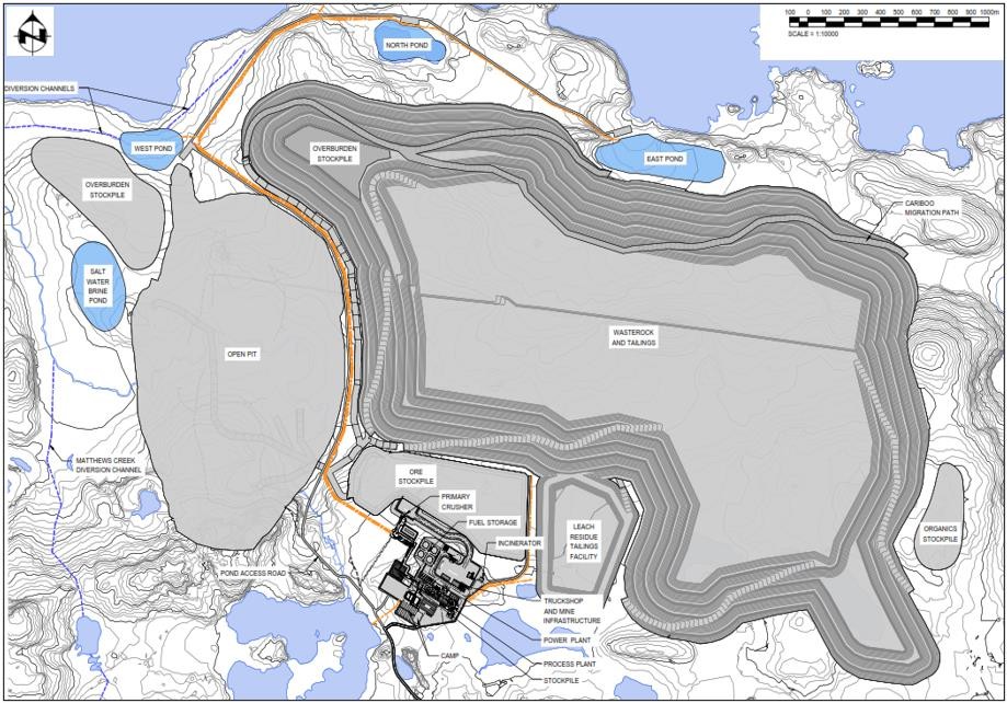
Source: Ausenco, 2023
The CPSF will be continuously constructed
over the life of the mine, even during winter months. Due to the delivery of waste rock from the open pit the paddock cells from years
10 through 16 require rehandling of waste rock to create cells for tailings storage to an ultimate elevation of 545 masl (height of 114
m). The CPSF will be progressively closed during operations when an external lift is completed. Tailings will be spigotted in multiple
cells during operations over the life of the project to ensure free water seeps into the waste rock and capture by the underdrain system.
During the winter months it is assume that 15 to 20% of the free water will be lost due to ice entrainment. The ultimate CPSF occupies
and area of 667 ha.
| 24.1.5.2.3 | Leach Residue Tailings Facility |
Due to the flat terrain, a ring
dike impounding structure is required to contain the leach residue tailings. The LRTF has been located south of the southeast corner of
the CPSF and 300 m east of the process plant and occupies an ultimate footprint of 33 ha. Prior to process
plant operations, it will be necessary to construct a starter embankment (Phase 1 LRTF) to an elevation of 444 masl (8 m high) to provide
storage capacity for the first two years of operations. Prior to constructing the facility, 0.3 m of topsoil and 0.5 m of overburden will
be removed from the starter footprint. The starter embankment will be constructed with waste rock and a geomembrane liner, 1 m of lower
permeability soil, and 2 m filter zone will be installed on the interior slopes of the embankment. The liner system will continue throughout
the base of this facility with a prepared subgrade and geomembrane. The construction materials for the starter embankment will be sourced
from the pre-mining open pit excavation.
| Courageous Lake Project | Page 366 |
| Pre-feasibility Study and Preliminary Economic Assessment NI 43-101 Technical Report | January 5, 2024 |
The LOM leach residue tailing generated
is only 1.5 Mt, which is less than 4% of the total tailing stream from the process plant. The ultimate LRTF will raise the crest to a
final elevation of 450 masl (an ultimate height of 15 m).
| 24.1.5.2.4 | CPSF
and LRTF Water Management |
The CPSF and LRFF water management
systems includes structures for surface water and seepage management. The surface water management will include three components:
| ● | Contact water from the CPSF and LRTF in open diversion channels that run on the
surface along the toe of these facilities. |
| ● | Seepage water in the foundation of both facilities that will be captured seepage
using an underdrain system. The underdrain for the CPSF has been designed to capture decant water (free water) from the tailings along
with seepage from precipitation. |
The diversion channels will collect
non-contact surface runoff from the natural areas surrounding the facility and drain to drainage areas outside the DSTF footprint. The
DSTF surface water collection system was designed to collect surface contact runoff and direct the water to the sediment ponds during
operation. The DSTF surface water collection channels will become non-contact water collection ditches after closure. The contact water
should only contain sediment from the facility and will be directed to sediment ponds and then pumped back to the process plant or discharged
to the environment. Water monitoring samples will be taken on a regular basis to ensure water being discharged meets water quality standards.
If the water does not meet standards, the water from the sediment ponds will be pumped to the filter plant, then combined with the filtrate
water and pumped to the process plant for water makeup or treated and discharged to the environment. The temporary and permanent channel
are designed to convey runoff from the 1-in-100-year and 1- in-200-year storm events, respectively. The non-surface or drainage water
management system will consist of HDPE dual wall pipe and drainage gravel wrapped in a non-woven geotextile to capture near-surface groundwater
and seepage from the tailings; capturing these water sources will minimize build-up of the phreatic surface in the base of the tailings
facility. In addition, the underdrain system will be utilized to drain surface runoff that is blocked by the DSTF from following its original
path. A ring-dyke filter system will be placed around the underdrain inlet to prevent solids from entering and potentially plugging the
system.
| Courageous Lake Project | Page 367 |
| Pre-feasibility Study and Preliminary Economic Assessment NI 43-101 Technical Report | January 5, 2024 |
| 24.1.5.2.5 | CPSF
and LRTF Geotechnical Instrumentation |
The stability of the CPSF and LRTF
will be monitored by vibrating wire piezometers strategically placed within the base of these facilities. In addition, inclinometers and
prisms will be placed on temporary and permanent exterior slopes during operation. Real-time continuous and unattended monitoring will
be employed for the geotechnical monitoring. Additionally, water quality monitoring instrumentation will be implemented for monitoring
of seepage and contact water from these facilities in the small facility ponds located around these facilities that discharge into the
larger collection ponds.
| 24.1.5.2.6 | Closure
and Reclamation |
The CPSF will provide long-term
storage of waste rock and flotation tailings and will remain in place beyond mine closure. For reclamation, the CPSF will be progressively
closed in stages following the completion of each outer permanent lift to maintain slope stability, minimize dust, minimize water infiltration,
and contaminant migration while being visually compatible with the surrounding area. The outer slopes of the waste rock will be graded
to flattened to 3:1 (H:V) as part of the operations to facilitate progressive closure. In addition, some flatter-sloped caribou access
ramps will be constructed at designated locations. Contact water and seepage water from CPSF will be collected in the water collection
ponds and be pumped to during operations for process water utilization or treated, if required, and released to the environment and post-closure
seepage and contact water will be pumped to the mined-out open pit until the water quality meets discharge criteria.
The LRSF due to the downstream construction
cannot be progressively closed during operations. For reclamation the remaining supernatant water in the LRTF will be pumped to the mined-out
open pit prior to closure. The leach residue tailings will be capped with a 2 m-thick layer of waste rock to support a closure cover system
over the tailings with a 3% grade away from the center to support potential settlement of the cap. A geomembrane with protective layers
above and below will be placed on the top to prevent seepage into the lined facility then covered with 2 m of waste rock. Then the waste
rock shell will be overlain by 2 m of overburden and 0.3 m of topsoil and vegetative cover to minimize the seepage and ingress of air
into the waste rock shell. After closure, the contact water from the LRTF will be pumped to the mined-out open pit until the quality of
the contact water meets discharge criteria.
| 24.1.5.3 | Electrical Power System |
| 24.1.5.3.1 | Facility
Power Supply |
The proposed diesel powerplant
will consist of seven modular diesel gensets, 1,800 rpm, each nominal 3.1 MW continuously rated (ancillary loads allowed for), three phase,
60 Hz, 13.8 kV, 0.8 PF leading, with water jacket and exhaust gas heat recovery, with indoor day tanks and local control panels plus networking
and PLC automatic master control, with gensets mounted in double wide sound attenuated modules with fire detection, fire suppression and
H&V for Arctic conditions. Note, the 3.1 MW nominal capacity is the genset output after subtracting related ancillary loads such as
cooling fans.
| Courageous Lake Project | Page 368 |
| Pre-feasibility Study and Preliminary Economic Assessment NI 43-101 Technical Report | January 5, 2024 |
The powerplant detailed layout
design drawings (001-2700-E-6501 to 001-2700-E-6504) include space for an additional eight genset if required, which will be further defined
during the next phase where provision will be made for future installation.
The modular powerplant will include
a double wide switchgear and control module including metal clad switchgear with 13.8 kV generator circuit breakers and circuit breakers
to feed the various plant loads. The switchgear will be split into two sections with a tie breaker and redundant station service and grounding
transformers such that any single fault will not cause a complete blackout.
| 24.1.5.3.2 | Site Power Reticulation |
Power will be distributed across
the site via 13.8 kV overhead lines originating from the plant’s 13.8 kV switchgear housed within the power plant electrical room.
Overhead distribution lines will
be constructed using aluminum conductor steel-reinforced cable (ACSR) and supported by wooden poles. The overhead powerlines will provide
power from the 13.8 kW switchgear to the collection pond pumphouse and explosive facilities.
| 24.1.5.3.3 | Plant
Power Distribution |
The largest electrical loads at
the process plant are the ball mill and oxygen plant. The drive systems for both includes motors, feeder drives (FDRs), and bypass switchgear
to minimize voltage disturbances throughout the power distribution system during start-up. The ball mill and oxygen plant drive systems
will be supplied via cable circuits from the plant’s primary 13.8 kV switchgear. All other process and non-Process Plant loads will
be powered via 4160 V and 600 V MCCs housed within electrical rooms strategically located throughout the plant area. Power will be stepped
down to 4.16 kV, 600 V, and 120/208 V distribution, as required via grounded pad-mounted and pole-mounted transformers.
Power to the electrical rooms will
be supplied by resistance-grounded, secondary substation-type, dry-type distribution transformers located adjacent to the respective electrical
room. All electrical rooms will be adequately rated for the environment and outfitted with lighting and small power transformers, distribution
boards, uninterrupted power supply (UPS) systems, fire alarm and detection, and HVAC systems designed for maintaining a positive pressure
with respect to outdoor ambient pressure. To reduce installation time, the electrical rooms will be pre-fabricated modular buildings installed
on structural framework above ground level for bottom entry of cables. Additionally, electrical rooms will be located as close as practical
to the electrical loads to optimize conductor sizes and minimize cable lengths.
The Project would require two water
treatment plants:
| 1. | A plant for treatment and discharge of mine contact water, including runoff and seepage from the co-placement
waste rock and tailings storage facility and excess process water from the LRTF. |
| Courageous Lake Project | Page 369 |
| Pre-feasibility Study and Preliminary Economic Assessment NI 43-101 Technical Report | January 5, 2024 |
| 2. | A treatment process for reducing the volume of saline groundwater that is expected to report to the
open pit when mining extends below the level of the basal cryopeg and below the permafrost. |
The contact water treatment plant
will include a ferric co-precipitation stage for removal of arsenic and total suspended solids followed by aerobic and anaerobic biological
processes for removing ammonia, nitrite and nitrate. Treated water will be pumped to Courageous Lake and discharged via a diffuser.
The saline groundwater treatment plant
uses a saltwater reverse osmosis process for concentrating the groundwater into to a brine with 6.5% salts. This brine cannot be discharged
but will be stored in a purpose-built reservoir until the end of operations. At that time, the brine will be transferred to the open pit.
The remainder of the pit will be filled with fresh water from Courageous Lake over a period of many years. The density difference between
the brine and fresh water will generate a stable chemocline and thereby prevent mixing of the brine and overlying fresh water. As such,
the brine is expected to remain in the bottom of the open pit lake in perpetuity.
At the end of operations, the saline groundwater
treatment plant would no longer be required and would therefore be decommissioned. However, the mine contact water treatment plant will
likely continue to operate seasonally for up to ten years until runoff and seepage from reclaimed mine waste areas have become negligible.
| 24.1.6 | Market Studies and Contracts |
No market studies or product valuations
were completed as part of the 2024 PEA. Market price assumptions were based on a review of public information, industry consensus, standard
practices, and specific information from comparable operations in the region.
Gold doré is widely traded
and can be marketed directly from producer to refinery or through third-party trading entities. Seabridge were not provided with indicative
refining, insurance, or transportation terms. Assumptions for metal payability, refining costs, transportation costs, and insurance costs
were estimated based on a review of information from comparable recent studies. The assumed transportation and refining terms are summarized
in Table 24-9 below, these refining and transport costs are deducted from the payable value of the metal to arrive at net smelter revenue
(NSR). Refining and transportation terms and costs are influenced by global supply and demand and governed by mine and refinery economics
based on metal prices and cost of operation. During operation, these terms may be based on variable annual negotiations, fixed rates,
and/or market benchmarks.
| Table 24-9: | Summary
of Assumed Doré Transportation and Refining Terms |
| Description |
Units |
Value |
| Payability – Au |
% |
99.80 |
| Transportation and refining cost |
C$/oz Au |
5.0 |
| Transportation Insurance |
% (of NSR) |
0.15 |
| Courageous Lake Project | Page 370 |
| Pre-feasibility Study and Preliminary Economic Assessment NI 43-101 Technical Report | January 5, 2024 |
| 24.1.6.2 | Commodity Price Projections |
Project economics were estimated
based on a long-term gold price of $1,850/oz and a C$ to US$ exchange rate (FX) of 0.740 US$/C$. These values are consistent with historic
prices, shown in Table 24-10. The QP also considers the prices used in this study to be consistent with the range of prices being used
for other project studies.
| Table 24-10: | Summary of Historic Commodity
Pricing (Source: Capital IQ Dec. 7, 2023) |
| Description |
Units |
Project Assumption |
1-Year Average |
2-Year
Average |
| Gold Price |
US$/oz Au |
1,850 |
1,927.2 |
1,844.59 |
| Exchange Rate (FX) |
US$/C$ |
0.74 |
0.740 |
0.755 |
No contracts for the transportation
or off-take of the gold doré are currently in place, but if they are negotiated, they are expected to be within industry norms.
Similarly, there are no contracts currently in place for the supply of reagents, equipment, utilities, labour, or bulk commodities required
to construct and operate the Project.
| 24.1.7 | Environmental Studies, Permitting and
Social or Community Impact |
The PEA mine plan representing
a modification and expansion of the PFS mine plan will require application to the Mackenzie Valley Land and Water Board (MVLWB) for amendments
to the Project water license and land use permit. After a preliminary screening, the MVLWB will make a determination to refer the Project
to the MacKenzie Valley Environmental Impact Review Board (MVEIRB). The MVEIRB is an independent body set up under the Mackenzie Valley
Resource Management Act (MVRMA) to consider and conduct environmental assessments of projects in the NWT. The MVEIRB has authority to
review Project scoping, terms of reference, workplans and ultimately recommendations to government of Canada decision.
A review of Courageous Lake baseline
study applicability to evaluate the potential effects of the PEA project will be required and may result in the need for expanded baseline
studies, monitoring or modelling to adequately inform an understanding of the project effects on the environment, mitigation, amendment
to PFS operational management plans and permits, consultations and Indigenous community engagement, and revisions to the mine closure
and reclamation plan.
New or expanded mine components
such as removal and treatment of saline groundwater from below permafrost, construction and operation of the LRTF, expanded CPSF and water
management facilities will require detailed engineering design to support permitting. Mine closure and environmental remediation plans
will be reviewed and amended to address the expanded scope and duration of mining operations and closure activities as part of mine permitting.
Mine closure and post-closure costs would be re-evaluated, represented in updated reclamation securities, and inform the LOM cost model.
PEA closure costs are summarized in Section 24.1.8.1.1.
| Courageous Lake Project | Page 371 |
| Pre-feasibility Study and Preliminary Economic Assessment NI 43-101 Technical Report | January 5, 2024 |
Valor Gold will need to review
its community engagement plans as mine planning advances for the PEA mine plan, and consider if additional efforts are required for communications,
engagement and community involvement. The PEA mine plan represents an opportunity to realize expanded social, economic and employment
benefits for communities in the region.
| 24.1.8 | 2024 PEA Capital and Operating Cost
Estimates |
| 24.1.8.1 | Capital Cost Estimate |
The capital cost estimate presented
in this PEA provide substantiated costs that can be used to assess the economics of the expanded mine plan in PEA Year 1 for the Project
(one year post PFS mine closure). The estimates are based on an extension of the PFS open pit mining operation, utilizing the existing
process plant and associated infrastructure.
The estimates conform to Class
5 guidelines for a PEA-level estimate with a -35%/ +50% accuracy according to AACE International. Both estimates were developed in Q4
2023 C$ based on the proposed design for the Project, with input data from budgetary quotations for equipment, service contracts, and
construction contracts; as well as Ausenco’s in-house database of similar projects and studies, which includes experience from similar
operations. Pricing has been converted to US$ for the purposes of this report using the C$ to US$ exchange rate of 0.74.
The capital and operating cost estimates have been prepared
or advised by the following groups:
| ● | Mining is prepared by Moose Mountain Technical Services Ltd. (MMTS). |
| ● | On-site Infrastructure (additional diesel storage tanks and accommodation camp), Tailings Facility, Consumables,
and G&A are prepared by Ausenco. |
| ● | Water Treatment Plant is prepared by SRK Consulting (Canada) Inc. (SRK). |
| ● | Owner’s and closure costs have been prepared by Seabridge. |
All cost amounts expressed are in US$ unless stated otherwise.
| Table 24-11: | 2024
PEA Capital Cost Estimate Summary (US$) |
| Overall
Site Capex |
Initial (US$M) |
Sustaining (US$M) |
Total
(US$M) |
| Mining |
336 |
412 |
748 |
| Process Plant |
0 |
0 |
0 |
| Tailings Facilities |
71 |
11 |
82 |
| On-Site Infrastructure |
39 |
11 |
50 |
| Off-Site Infrastructure |
0 |
0 |
0 |
| Subtotal Direct Costs |
446 |
432 |
878 |
| Indirects, Owner’s Costs & Contingency |
83 |
17 |
100 |
| Total |
529 |
450 |
979 |
Note: Values may not sum due to rounding
| Courageous Lake Project | Page 372 |
| Pre-feasibility Study and Preliminary Economic Assessment NI 43-101 Technical Report | January 5, 2024 |
The total closure costs for the
PEA, inclusive of the process plant, water treatment plant and tailings area, has been calculated to be US$105 M, with salvage credits
of US$27 M.
| 24.1.8.2 | Operating Cost Estimate |
The PEA pit mining costs are estimated
to be US$45.78/t milled or US$3.00/t mined. It includes the labour, maintenance, major component repairs, fuel and consumable costs. The
estimates are derived by MMTS from a combination of supplier quotes and historical data.
As the PEA utilizes the existing
PFS process plant at PEA Year 1, the processing cost (Table 24-17, Table 24-18) is based on the PFS design. The CSPF costs are increased
as the facility required is larger due to the larger quantity of mining involved.
G&A (Table 24-19, Table 24-20)
costs are also larger due to the larger mining fleet during operation which affect mainly the travel and camp.
SRK also provided detail for the
operation of the second water treatment plant (Table 24-21) to reduce saline groundwater, which operates for 13 years during operation
of the LOM, this will be operated on top of the existing water plant.
| Table 24-12: | 2024
PEA Operating Cost Estimate Summary Average, Excluding Capitalized Opex, Closure Bonding
(C$) |
| Overall Site OPEX |
Annual OPEX
(C$M/a) |
Per Tonne Milled OPEX
(C$/t milled) |
TOTAL OPEX
(C$M) |
% |
| Mining |
170 |
61.9 |
2,689 |
55.1 |
| Processing |
106 |
38.6 |
1,678 |
34.4 |
| G&A |
29 |
10.6 |
460 |
9.4 |
| Water Treatment |
3 |
1.2 |
50 |
1.0 |
| Total |
307 |
112.2 |
4,877 |
100 |
Note: Values may not sum due to rounding
| Table 24-13: | 2024
PEA Operating Cost Estimate Summary Average (US$) |
| Overall Site OPEX |
Annual OPEX
(US$M/a) |
Per Tonne Milled OPEX
(US$/t milled) |
TOTAL OPEX
(US$M) |
% |
| Mining |
125 |
45.8 |
1,990 |
55.1 |
| Processing |
78 |
28.6 |
1,242 |
34.4 |
| G&A |
21 |
7.8 |
340 |
9.4 |
| Water Treatment |
2 |
0.9 |
37 |
1.0 |
| Total |
227 |
83.0 |
3,609 |
100 |
Note: Values may not sum due to rounding
| Courageous Lake Project | Page 373 |
| Pre-feasibility Study and Preliminary Economic Assessment NI 43-101 Technical Report | January 5, 2024 |
| Table 24-14: | Maximum
Hourly Labour Schedule |
| Hourly
Labour Allocation Summary |
Year
2 |
| Mine Operations |
| Drill Operator |
20 |
| Blasters |
14 |
| Shovel Operator |
21 |
| Haul Truck Driver |
9 |
| Grader Operator |
14 |
| Excavator Operator |
15 |
| Loader Operator |
6 |
| Track Dozer Operator |
36 |
| Blaster’s Helper |
14 |
| Water Truck Operator |
9 |
| Fuel Truck Operator |
18 |
| Mine
Maintenance |
| Electrician |
22 |
| HD Mechanic |
40 |
| LD Mechanic |
2 |
| Machinist |
16 |
| Crane Operator |
0 |
| Welder |
16 |
| Labourer Service man |
16 |
| Total Hourly |
288 |
| Table 24-15: | Maximum
Salaried Labour Schedule |
| Position |
Year
2 |
| Mine
Operations |
| Mine Manager |
1 |
| Mine Superintendent |
1 |
| Clerks |
2 |
| Mine General Supervisor |
2 |
| Shift Supervisor |
4 |
| Drilling and Blasting Supervisor |
2 |
| Pit Labourers |
8 |
| Safety Trainers |
1 |
| Autonomous Technician |
4 |
| Mine
Maintenance |
|
| Maintenance General Supervisor |
2 |
| Courageous Lake Project | Page 374 |
| Pre-feasibility Study and Preliminary Economic Assessment NI 43-101 Technical Report | January 5, 2024 |
| Position |
Year 2 |
| Senior Maintenance Planner |
1 |
| Maintenance Planner |
2 |
| Maintenance Supervisor |
4 |
| Maintenance Superintendent |
1 |
| Mine
Engineering |
|
| Senior Geologist |
1 |
| Senior Mine Engineer |
2 |
| Mine Engineer |
1 |
| Junior Engineer |
1 |
| Surveyor |
2 |
| Mine Geologist |
3 |
| Ore Grade Technicians |
2 |
| Drill and Blast Engineer/Geotechnical Engineer |
2 |
| Mine Superintendent |
1 |
| Total Salaried |
50 |
| Table 24-16: | Mining
Costs (including Pre-production) per Tonne Mill Feed LOM Cost |
| Cost/Tonne
ROM Mill Feed |
(C$/t) |
(US$/t) |
| Grade Control |
1.04 |
0.77 |
| Drilling |
5.11 |
3.78 |
| Blasting |
9.90 |
7.33 |
| Loading |
7.76 |
5.74 |
| Hauling |
29.31 |
21.69 |
| Road Maintenance |
2.76 |
2.04 |
| Waste Dump Maintenance |
1.16 |
0.86 |
| Primary Pit Support |
6.23 |
4.61 |
| Secondary Pit Support |
0.25 |
0.19 |
| Mine Maintenance |
0.16 |
0.12 |
| Geotech/Site |
0.20 |
0.15 |
| Unallocated Labour Costs |
0.73 |
0.54 |
| Direct Costs - Subtotals |
64.60 |
47.80 |
| Mine Operations GME - Labour |
1.39 |
1.03 |
| Mine Maintenance GME - Labour |
0.88 |
0.65 |
| Technical Services GME - Labour |
1.13 |
0.84 |
| Total GME Costs |
3.40 |
2.52 |
| Total Operating Cost |
68.00 |
50.32 |
Note: Values may not sum due to rounding
| Courageous Lake Project | Page 375 |
| Pre-feasibility Study and Preliminary Economic Assessment NI 43-101 Technical Report | January 5, 2024 |
| Table 24-17: | PEA
Process Plant Operating Costs, Fixed and Variable Costs (CAD$) |
Process Plant Breakdown
Cost Center |
Annual LOM
C$M/a |
Per Tonne Milled LOM
C$/t milled |
TOTAL LOM
C$M |
| Fixed Cost |
| Labour |
22.5 |
8.22 |
357 |
| Maintenance |
6.5 |
2.38 |
104 |
| Total Fixed Cost |
29.0 |
10.60 |
461 |
| Variable Costs |
| Reagents & Process Consumables |
16.5 |
6.03 |
262 |
| Power |
49.0 |
17.88 |
777 |
| Tailings Paddock |
3.6 |
1.30 |
57 |
| Total Variable Costs |
69.1 |
25.21 |
1,096 |
| Overall Process OPEX Total |
98.1 |
35.82 |
1,557 |
Note: Values may not sum due to rounding
| Table 24-18: | PEA
Process Plant Operating Costs, Fixed and Variable Costs (US$) |
Process Plant
Breakdown
Cost Center |
Annual LOM
US$M/a |
Per Tonne Milled
LOM
US$/t milled |
TOTAL LOM
US$M |
| Fixed Cost |
| Labour |
16.7 |
6.08 |
264 |
| Maintenance |
4.8 |
1.76 |
77 |
| Fixed Cost |
21.5 |
7.85 |
341 |
| Variable
Costs |
| Reagents & Process Consumables |
12.2 |
4.46 |
194 |
| Power |
36.3 |
13.23 |
575 |
| Tailings Paddock |
2.6 |
0.97 |
42 |
| Variable Costs |
51.1 |
18.66 |
811 |
| Overall Process OPEX Total |
72.6 |
26.50 |
1,152 |
Note: Values may not sum due to rounding
| Table 24-19: | PEA
G&A Cost Areas (C$) |
| G&A
Area |
Year 1 (C$M/a) |
Year
1 (C$/t milled) |
%
of G/A |
| G&A Labour |
4.64 |
1.69 |
13.8 |
| General Expenses |
3.22 |
1.17 |
9.6 |
| G&A Vehicles |
0.14 |
0.05 |
0.4 |
| Contract Services |
5.53 |
2.02 |
16.5 |
| Travel and Camp Costs |
18.05 |
6.59 |
53.9 |
| Courageous Lake Project | Page 376 |
| Pre-feasibility Study and Preliminary Economic Assessment NI 43-101 Technical Report | January 5, 2024 |
| G&A
Area |
Year 1 (C$M/a) |
Year
1 (C$/t milled) |
%
of G/A |
| Potable Water & Waste Management |
0.55 |
0.20 |
1.6 |
| Other |
1.39 |
0.51 |
4.1 |
| Total |
33.51 |
12.23 |
100.0 |
| Table 24-20: | PEA
G&A Cost Areas (US$) |
| G&A Area |
Year 1 (US$M/a) |
Year 1 (US$/t milled) |
%
of G/A |
| G&A Labour |
3.43 |
1.25 |
13.8 |
| General Expenses |
2.38 |
0.87 |
9.6 |
| G&A Vehicles |
0.10 |
0.04 |
0.4 |
| Contract Services |
4.09 |
1.49 |
16.5 |
| Travel and Camp Costs |
13.36 |
4.88 |
53.9 |
| Potable Water & Waste Management |
0.41 |
0.15 |
1.6 |
| Other |
1.03 |
0.38 |
4.1 |
| Total |
24.80 |
9.06 |
100.0 |
| Table 24-21: | Desalination
Plant part of Water Treatment Plant |
| Mine
Year |
NET TDS Load to be Treated
per annum (t) |
Yearly Total OPEX
(US$M) |
| Year 1 |
1,556 |
0.2 |
| Year 2 |
2,772 |
0.3 |
| Year 3 |
3,836 |
0.4 |
| Year 4 |
4,609 |
0.4 |
| Year 5 |
5,146 |
0.4 |
| Year 6 |
5,820 |
0.4 |
| Year 7 |
43,611 |
4.7 |
| Year 8 |
46,242 |
3.4 |
| Year 9 |
50,401 |
3.0 |
| Year 10 |
55,469 |
2.8 |
| Year 11 |
58,458 |
2.8 |
| Year 12 |
62,093 |
2.8 |
| Year 13 |
65,698 |
2.9 |
| Total LOM |
405,711 |
24.6 |
| Courageous Lake Project | Page 377 |
| Pre-feasibility Study and Preliminary Economic Assessment NI 43-101 Technical Report | January 5, 2024 |
| 24.1.9 | 2024 PEA Economic Analysis |
The results of the economic analysis
for the 2024 PEA discussed in this section represent forward looking information as defined under Canadian securities law. The results
depend on inputs that are subject to known and unknown risks, uncertainties, and other factors that may cause actual results to differ
materially from those present here. Information that is forward-looking includes the following:
| ● | Mineral Resource Estimate. |
| ● | Assumed commodity prices and exchange rates. |
| ● | The proposed mine production plan. |
| ● | Projected mining and process recovery rates. |
| ● | Assumptions as to mining dilution and ability to mine in areas previously exploited using envisioned
mining methods for the timing and amount of estimated future production. |
| ● | Sustaining costs and proposed operating costs. |
| ● | Assumptions as to closure costs, closure bonding, and closure requirements. |
| ● | Assumptions as to environmental, permitting, and social risks. |
Additional risks
to the forward-looking information includes the following:
| ● | Change to costs of production from what is assumed. |
| ● | Unrecognized environmental risks. |
| ● | Unanticipated reclamation and monitoring expenses. |
| ● | Unexpected variations in quantity of mineralized material, grade, or recovery rates. |
| ● | Accidents, labour disputes, and other risks of the mining industry. |
| ● | Geotechnical or hydrogeological conditions during mining being different from what is assumed. |
| ● | Failure of mining methods to operate as anticipated. |
| ● | Failure of plant, equipment, or processes to operate as anticipated. |
| ● | Changes to assumptions as to the availability of electrical power, and the power rates used in the operating
cost estimates and financial analysis. |
| ● | Ability to maintain the social license to operate. |
| ● | Changes to interest rates. |
| Courageous Lake Project | Page 378 |
| Pre-feasibility Study and Preliminary Economic Assessment NI 43-101 Technical Report | January 5, 2024 |
The methodology for evaluation
of the PEA section of this Project is identical to that detailed in Section 22.2. The capital and operating cost estimates developed specifically
for this Project are presented in Section 24.1.8.
Industry common practice where mineralization
extends at depth beyond open pit mining is to transition the mining method from open pit to underground without pausing the mining activity
to accommodate the transition. The 2024 PEA assumes the predevelopment period and associated costs are exclusive from the 2022 PFS; however,
an opportunity exists to improve the 2024 PEA’s business case by investing free cash flow from the tail end of the operations described
in the 2024 PFS as the initial capital for the 2024 PEA.
The following assumptions have been
used for the 2024 PEA:
| ● | Construction period of two years. |
| ● | Total PEA mine life of 15.9 years. |
| ● | All cash flows discounted to start of the 2024 PFS construction period using mid-year discounting. |
| ● | Cost estimates in constant Q4 2023 Canadian dollars with no inflation or escalation factors considered. |
| ● | Results based on 100% ownership with a 2.0% net smelter return (NSR) royalty. |
| ● | Capital cost funded with 100% equity (no financing cost assumed). |
| ● | All metal products are sold in the same year they are produced. |
| ● | Project revenue is derived from the sale of gold doré. |
| ● | No contractual arrangements for refining or transportation currently exist. |
| 24.1.9.2 | Economic Analysis |
The economic analysis of the 2024
PEA was performed assuming a 5% discount rate in line with comparable precious metals projects in similar geographies. On a pre-tax basis,
the NPV discounted to start of PFS construction at 5% is US$230.6M, the internal rate of return (IRR) is 10.5%, and the payback period
is 9.2 years. On a post-tax basis, the NPV discounted at 5% is US$104.1M, the internal rate of return (IRR) is 7.8%, and the payback period
is 9.5 years. A summary of project economics is tabulated in Table 24-22.
Readers are cautioned that the PEA is preliminary
in nature. It includes inferred mineral resources that are considered too speculative geologically to have the economic considerations
applied to them that would enable them to be categorized as mineral reserves, and there is no certainty that the PEA will be realized.
| Courageous Lake Project | Page 379 |
| Pre-feasibility Study and Preliminary Economic Assessment NI 43-101 Technical Report | January 5, 2024 |
| Table 24-22: | 2024 PEA
Economic Analysis Summary |
| Description |
Units |
LOM
Total / Avg. |
| Gold Price |
US$/oz |
1,850 |
| FX Rate |
C$:US$ |
0.74 |
| Mine Life |
Years |
15.9 |
| Total Mill Feed |
Mt |
43.5 |
| Average Annual Mill Feed |
kt/a |
2,739 |
| Total Waste Mined |
Mt |
719.2 |
| Strip Ratio |
t:t |
16.6 |
| Production |
Units |
LOM
Total / Avg. |
| Mill Feed Grade – Au |
g/t |
2.62 |
| Total Metal Content – Au |
koz |
3,658 |
| Metal Recovery Rate – Au |
% |
89.3 |
| Total Metal Production – Au |
koz |
3,267 |
| Average Annual Metal Production - Au |
koz/a |
206 |
| Total Payable Metal – Au |
koz |
3,261 |
| Average Annual Payable Metal Production - Au |
koz/a |
205 |
| Operating
Costs |
Units |
LOM
Total / Avg. |
| Mining Cost |
US$/t mined |
3.00 |
| Mining Cost |
US$/t milled |
45.8 |
| Processing Cost |
US$/t milled |
28.6 |
| G&A Cost |
US$/t milled |
7.8 |
| Water Treatment Cost |
US$/t milled |
0.9 |
| Total Operating Cost (Excl. Closure Bonding) |
US$/t milled |
83 |
| Closure Bond Premium |
US$/t milled |
0.8 |
| C1 Cash Costs1 |
US$/oz Au |
1,161 |
| C3 Cash Costs (AISC)2 |
US$/oz Au |
1,323 |
| Capital
Costs |
Units |
LOM
Total / Avg. |
| Initial Capital Cost |
US$M |
529 |
| Sustaining Capital |
US$M |
450 |
| Salvage Credit |
US$M |
27 |
| Closure Costs |
US$M |
105 |
| Total Revenue |
US$M |
6,032 |
| Average Annual Revenue |
US$M |
379 |
| EBITDA |
US$M |
2,248 |
| Average Annual EBITDA |
US$M |
141 |
| Economic
Outcomes |
Units |
Pre-Tax |
Post-Tax |
| NPV (5%) Discounted to Start of 2024 PFS Construction |
US$M |
231 |
104 |
| IRR |
% |
10.5 |
7.8 |
| Payback |
Years |
9.2 |
9.5 |
Note:
| 1. | Cash Costs consist of mining costs, processing costs, mine-level G&A, closure bond premiums, off-site charges, and royalties. |
| 2. | All-In Sustaining Costs includes cash costs plus sustaining capital, closure costs, and salvage credits. |
| Courageous Lake Project | Page 380 |
| Pre-feasibility Study and Preliminary Economic Assessment NI 43-101 Technical Report | January 5, 2024 |
| 24.1.9.3 | Sensitivity Analysis |
A sensitivity analysis was conducted
on the base case pre-tax and post-tax NPV and IRR of the PEA Project using the following variables: metal price, discount rate, total
operating cost, and initial capital cost. The sensitivity analysis shows that the 2024 PEA is most sensitive to metal price, exchange
rate, and operating cost. The PEA sensitivity to gold price and discount rate are shown in Table 24-23 below. Figure 24-12 shows a summary
of the post-tax sensitivity analysis results.
| Table 24-23: | 2024
PEA Economic Sensitivity to Gold Price and Discount Rate |
| Scenario |
Units |
Lower Case |
Base Case |
Spot Case
(Dec. 3, 2023) |
High Case |
| Gold
Price |
US$/oz |
1,750 |
1,850 |
2,130 |
2,50 |
| NPV1 |
1% Discount Rate |
US$M |
374 |
545 |
1,019 |
1,638 |
| 3% Discount Rate |
US$M |
143 |
260 |
581 |
994 |
| 5% Discount Rate |
US$M |
23 |
104 |
324 |
604 |
| 8% Discount Rate |
US$M |
(51) |
(4) |
125 |
285 |
| 10% Discount Rate |
US$M |
(66) |
(32) |
59 |
171 |
| IRR1 |
% |
5.6 |
7.8 |
14.2 |
22.3 |
| NPV2 |
5% Discount Rate |
US$M |
42 |
187 |
583 |
1,085 |
Note:
| 1. | Discounted to start of 2024 PFS mine construction. |
| 2. | Discounted to start of 2024 PEA mine construction (end of 2024 PFS mine life) |
| Courageous Lake Project | Page 381 |
| Pre-feasibility Study and Preliminary Economic Assessment NI 43-101 Technical Report | January 5, 2024 |
| Figure 24-12: | PEA Post-tax
NPV and IRR Sensitivity Results |

Source: Ausenco, 2023
| Courageous Lake Project | Page 382 |
| Pre-feasibility Study and Preliminary Economic Assessment NI 43-101 Technical Report | January 5, 2024 |
| 25 | INTERPRETATION AND CONCLUSIONS |
| 25.1 | Interpretation and Conclusions for the 2024 PFS |
The QPs note the following interpretations
and conclusions in their respective areas of expertise, based on the review of data available for this Report.
| 25.1.2 | Mineral Tenure, Surface Rights, Water Rights, Royalties and Agreements |
The Courageous Lake property is comprised
of 85 Northwest Territorial Mining Leases and four Federal Mining Leases having a combined area of 50,239.96 ha. All of the mining leases
are currently recorded 100% to Seabridge Gold (NWT) Inc., a wholly owned subsidiary of Seabridge Gold Inc . Upon completion of the spin-out,
Valor Gold will have a 100% interest in Seabridge NWT Inc.
Exploration has been primarily through
drilling of the deposits. A total of 1,099 drill holes containing 284,086 m of drilling with 176,456 m assayed for at least Au are in
the Project database. The quantity and quality of the lithological, geotechnical, collar, and down-hole survey data collected from the
drill programs are sufficient to support Mineral Resource estimation. There are no known sampling or recovery factors that could materially
impact the accuracy and reliability of the results.
| 25.1.4 | Analytical Data Collection and QA/QC |
Seabridge era drilling contained sufficient
QA/QC procedures with acceptable results to support the Resource Estimate. Historic data from Noranda and Placer dome era drilling is
validated through the use of Point Validation, which compares the historic drilling to the recent drilling. Based on this validation work,
all drillhole data within the database has been used to inform the MRE.
| 25.1.5 | Metallurgical Testwork |
Six metallurgical test programs
were conducted on samples from the Courageous Lake deposit between 2003 and 2023. SGS-Lakefield Research Ltd. (Lakefield) conducted the
metallurgical testing programs in 2003/2004 and in 2010/2011 which included investigations into comminution, flotation and gravity concentration,
flotation concentrate pre-treatments by bio-oxidation (BIOX) and POX, cyanide leaching, and POX slurry neutralization.
G&T Metallurgical Services
Ltd. (G&T) carried out a test work program in 2007 focused on optimizing flotation performance. Based on the 2007 work program, G&T
conducted the 2012 test program to further investigate flotation optimization, and prepared concentrates for POX tests that were carried
out in 2012 by Sherritt Technologies, a division of Sherritt International Corp.
(Sherritt). Sherritt also conducted cyanide amenability (CNA) tests on the POX residues and cyanide destruction tests on the cyanide leach
residues.
| Courageous Lake Project | Page 383 |
| Pre-feasibility Study and Preliminary Economic Assessment NI 43-101 Technical Report | January 5, 2024 |
The most recent test program was
completed by ALS Kamloops in 2023 which included eight variability samples representing a range of grade, depth, and zone parameters from
eight drill cores. The test work included ball mill grindability, flotation concentration, and flotation tails leaching.
Modal mineralogy indicates that the
predominant sulphide minerals contained across the samples were arsenopyrite, pyrite, and pyrrhotite. The gold occurred as liberated gold,
or refractory gold associated with sulphides (primarily arsenopyrite) and silicates. Gold grain sizes ranged from sub-microscopic size
to 70 µm. The gangue mineralogy was dominated by quartz, micas, feldspar, and calcium carbonate.
The results of the comminution
tests indicate that the material is very competent with respect to breakage in a SAG mill. The Bond ball mill work index results suggest
that the material is of moderate hardness with respect to grinding in a ball mill, and a BMWi value of 16.5 kWh/t was used for grinding
circuit design.
The test work results indicate that
the material does not exhibit a strong response to gold recovery through gravity concentration; however, the mineralization responds well
to flotation concentration. Gold recovery by flotation was high, ranging from 85 to 97%. The POX and cyanidation tests by Lakefield and
Sherritt indicated a significant improvement in gold extraction when the flotation concentrate underwent a high degree of POX. The testing
programs showed that over 98% of the sulfide sulfur can be oxidized with the standard conditions practiced in the POX industry. The test
work indicated that gold extraction improved substantially with increasing sulfur oxidation. The Lakefield and Sherritt test results showed
that the gold extractions from the POX residues varied from 94 to 99%.
Robust metallurgical projection
models have been derived from open circuit and locked cycle bulk rougher flotation and single-stage cleaner flotation tests of the Courageous
Lake master composites and variability samples and are appropriate for this level of study.
The deleterious element assay for
eight variability samples from ALS 2023 test program indicate that all samples contained less than one ppm of mercury, which was the laboratory’s
detection point. It does not appear that mercury would become a deleterious element in the final doré; however, further analysis
may be required to confirm the precise mercury concentration at lower detection point.
In 2013, SGS Lakefield performed
test work on Walsh Lake deposit located near Courageous Lake deposit. The results bottle roll cyanidation tests show that Walsh Lake samples
are amenable to leaching by standard, direct cyanidation procedures and does not show any indication of material being refractory. The
test results indicated flotation to be effective in concentrating the gold and sulfide minerals of Walsh Lake deposit. Rougher flotation
tests show gold recoveries ranging from 88% to 95% with mass pulls ranging from 14.5% to 23%.
| 25.1.6 | Mineral Resource Estimate |
The Courageous Lake and
Walsh Lake deposit MREs have a base case cut-off grade of 0.8 g/t. The Courageous Lake deposit contains 11.0 Moz of Au in the
Measured and Indicated categories within 145 Mt at a mean Au grade of 2.36 g/t. There is an additional 3.3 Moz of Au in the Inferred
category at Courageous Lake.
| Courageous Lake Project | Page 384 |
| Pre-feasibility Study and Preliminary Economic Assessment NI 43-101 Technical Report | January 5, 2024 |
Walsh Lake contains an additional
552 koz of Au in the Inferred category within 4.1 Mt at an average Au grade of 4.2 g/t.
The following factors could affect the
mineral resources:
| ● | Commodity price and exchange rate assumptions. |
| ● | Pit slope angles and other geotechnical factors. |
| ● | Assumptions used in generating the LG pit shell, including
metal recoveries, and mining and process cost assumptions. |
The open pit mine plan in the 2024
PFS establishes an economic mine plan that uses Measured and Indicated Resources and stays within the permafrost zone, providing mill
feed at a nominal rate of 7,500 t/d. The LOM plan accommodates the local adverse conditions comprising snow, cold, and remoteness. Waste
and water management designs are incorporated into the mine plan, as specified in the current site plans. The chosen mine equipment is
well known and suitable for the expected operating conditions, and the productivity assumptions are reasonable and achievable. Given the
stated design parameters and assumptions, the open pit mine plan is expected to achieve the forecasted production schedule and annual
costs within the typical range of accuracy for a PFS-level study.
The process plant flowsheet designs
were based on previous studies, testwork results, financial evaluations, and industry standard practices. Most of the unit operations
selected to build the plant flowsheet are standard technologies widely used in gold processing plants with no significant elements of
technological innovation. The POX circuit is technologically complex and requires skilled operators.
The plant is designed for a throughput
of 2.74 Mt/a with availability of 90%. The crusher plant circuit design is set at 65% availability and the gold room availability is set
at 52 weeks/a. The project has an estimated life of 13 years.
The selected flowsheet includes
a three-stage crushing circuit, with crushed product reporting to the crushed ore stockpile. Mineralized material is reclaimed to a grinding
circuit consisting of a ball mill circuit operating in closed circuit with a cyclone cluster. Classified material reports to rougher flotation,
where concentrate is separated from the gangue material and fed to cleaner flotation. In the cleaning circuit, the concentrate grades
are upgraded prior to further size reduction in a regrind ball mill operating in closed circuit with a cyclone cluster. Cleaner tailings
combine with rougher tailings for thickening before being discharged to the CPSF. Overflow from regrind cyclones undergoes acidulation
and pre-oxidation stages followed by the POX circuit which will effectively oxidize the sulphide concentrate. The oxidized concentrate
is leached and then washed in six stages through a CCD circuit. The resulting pregnant solution will be processed using a Merrill-Crowe
treatment by adding zinc powder to precipitate gold and silver. The precious metals precipitate will be smelted on site to produce gold-silver
doré bars.
| Courageous Lake Project | Page 385 |
| Pre-feasibility Study and Preliminary Economic Assessment NI 43-101 Technical Report | January 5, 2024 |
| 25.1.9 | Project Infrastructure |
The Project site will be accessible
by the Courageous Lake Mine spur winter road, connecting to the Tibbitt to Contwoyto winter road (TCWR) that is normally open from late
January/early February until the end of March of each year.
The Courageous Mine spur winter road accessed
from the TCWR and is estimated to be 26 km in length with 7 km on land (with small lakes interspersed) and 19 km on the larger Mackay
Lake. From the Courageous Lake Mine spur road intersection to the TCWR it is 76 km to the Lockhart Lake maintenance camp. The Lockhart
Lake maintenance camp is at station 170 km from the TCWR start at Tibbitt Lake.
| 25.1.9.2 | Site Infrastructure |
Infrastructure to support the Project
will consist of site civil works, site facilities/buildings, on-site roads, a water management system, and site electrical power. Site
facilities will include both mine facilities and process facilities as follows:
| ● | Mining facilities including the mine office and dry, truck
shop, tire change facility, truck wash, explosives storage and manufacturing facility, diesel fuel storage and distribution, and ore
stockpile. |
| ● | Processing facilities including the primary, secondary and
tertiary crushing, ROM stockpile and reclaim conveyors, fine ore stockpile, process plant, office and laboratory, plant maintenance building. |
| ● | Mine waste and water management infrastructure including:
mine waste and tailings storage facility, tailings distribution system, water reclaim system, downstream water management ponds, and
overburden stockpiles. |
| ● | General facilities including the camp, gatehouse, emergency
response/ambulance bay, warehouse, reagent cold storage, administration building, communications, emergency power diesel storage, potable
fresh, process and potable water storage and distribution, power plant, site sewage system, and solid waste treatment. |
| ● | The processing plant will comprise several pre-engineered
and stick built buildings in addition to a fabric geodesic dome. |
| ● | A 204 bed permanent accommodation camp will be located south
of the process plant, connected via an arctic corridor. The camp will be installed at the beginning of construction to house construction
personnel and will then be maintained for operating staff. |
| 25.1.9.3.1 | Electrical Power Supply |
The proposed diesel powerplant will
consist of seven (7) modular diesel gensets, 1800 rpm, each nominal 3.1 MW continuously rated (ancillary loads allowed for), 3 phase,
60 Hz, 13.8 kV, 0.8 PF leading, with water jacket and exhaust gas heat recovery, with indoor day tanks and local control panels plus networking
and PLC automatic master control, with gensets mounted in double
wide sound attenuated modules with fire detection, fire suppression and H&V for arctic conditions.
| Courageous Lake Project | Page 386 |
| Pre-feasibility Study and Preliminary Economic Assessment NI 43-101 Technical Report | January 5, 2024 |
There is an opportunity to evaluate
a nuclear microreactor power plan as an alternative solution to diesel power for the project, at a cost per kWh that is comparable to
diesel costs. The microreactor plant will generate enough electricity to power all mine loads, with leftover heat available for supply
to the plant heating system.
| 25.1.9.3.2 | Site Power Distribution |
Power will be distributed across
the site via 13.8 kV overhead lines originating from the plant’s 13.8 kV switchgear housed within the primary electrical rooms at
the outdoor substation.
The ball mill and oxygen plant
drive systems will be supplied via cable circuits from the plant’s primary 13.8 kV switchgear. All other process and non-Process
Plant loads will be powered via 4160 V and 600 V motor control centers (MCCs) housed within electrical rooms strategically located throughout
the plant area. Power will be stepped down to
4.16 kV, 600 V, and 120/208 V distribution,
as required via grounded pad-mounted and pole-mounted transformers.
| 25.1.9.4 | Co-placement Storage Facility and Leach Residue Tailings Facility |
Waste management consists of the containment
and long-term management of waste products developed during the LOM operations that consist of waste rock and tailings. Waste rock will
be generated during the mining of economical ore. Tailings is a waste product of mineral exaction that consists of two tailings streams:
flotation tailings and neutralized leach residue tailings from POX circuit. The flotation tailings will be co-placed with waste rock and
the neutralized tailings will be placed in a separate facility.
Both facilities are located east
of the open pit. The CPSF is an unlined facility that will utilize waste rock to construct paddock cells for the storage of flotation
slurry tailings. This facility is designed to store 297.8 Mt of flotation tailings and waste rock. The LRTF is a lined facility to prevent
constituents of concern migrating out of the facility. The facility is designed to contain 1.1 Mt of leach residue tailings. Each facility
will be closed with a cap consisting of 2 m of overburden and 0.3 m of topsoil and vegetative cover. The CPSF will be closed progressively
during operations and the LRTF will be closed at the end of the mine life.
These facilities are designed in accordance
with local and national standards for tailings and waste rock storage.
The objective of surface water management
is to protect groundwater and surface water resources. A site-wide management strategy, encompassing the design of water management structures,
hydrology considerations, and a site-wide water balance was developed for the site. The review and interpretation of existing climate
data, encompassing factors such as precipitation, snowfall, and evaporation, are crucial for accurately estimating water balance and designing
effective water management structures. Surface water runoff that comes into contact with disturbed areas will be managed prior to being
released to the surrounding environment. Runoff from disturbed areas will be collected in gravity ditches
and conveyed to pond or back into the pits. Diversions will capture non-contact water away from facilities and convey it to their natural
discharge location.
| Courageous Lake Project | Page 387 |
| Pre-feasibility Study and Preliminary Economic Assessment NI 43-101 Technical Report | January 5, 2024 |
Mine contact water from the open
pit, waste rock and tailings management area and residual processing water will be collected in the West or South satellite pits and pumped
from there to the mine water treatment plant where parameters such as arsenic, nitrate, and ammonia will be removed. Treated effluent
will be pumped from the plant to Courageous Lake where it will be discharged through a diffuser. Clean water from an undeveloped catchment
to the east of the Project area will be diverted away from the waste rock and tailings management facility and directed towards Courageous
Lake. Fresh water for processing of ore will be sourced from Courageous Lake.
| 25.1.10 | Environmental, Permitting and Social Considerations |
Courageous Lake Project has been
the subject of two decades of environmental baseline studies which prepare the Project well to advance towards a formal Environmental
Assessment. Northwest Territories Environmental Assessment processes are well-defined. Integrating environmental considerations with mine
plan and mine closure/reclamation design is key to gaining social license support for the project through proactive commitments to consultation
with communities, Indigenous communities and governments, NWT and federal regulators and other stakeholders with interests. The Project
site environmental concerns for permafrost, Northern Caribou, fish and water quality can be mitigated and in the opinion of the QP there
are no material barriers to advancement of the Project through permitting.
| 25.1.11 | Capital Cost Estimate |
The estimates conform to Class
4 guidelines for a PFS-level estimate with a -20%/ +25% accuracy according to AACE International. This estimated was developed in Q4 2023
C$ based on the proposed design for the Project, with input data from budgetary quotations for equipment, service contracts, and construction
contracts; as well as Ausenco’s in-house database of similar projects and studies, which includes experience from similar operations.
Pricing has been converted to US$ for the purposes of this report using the C$ to US$ exchange rate of 0.74.
| 25.1.12 | Operating Cost Estimate |
The estimate conforms to Class 4
guidelines for a PFS study level estimate with a -20%/+25% accuracy according to the Association of the Advancement of Cost Engineering
International (AACE International).
The operating cost estimate was developed
in Q3 2023 and comprises the ongoing cost of operations related to mining, processing, tailings co-disposal, general administration activities,
and water treatment costs. The estimate is based on a combination of first-principal calculations, experience, vendor quotes, reference
projects and factors appropriate for this level of study. Pricing has been converted to US$ for the purposes of this report using the
C$ to US$ exchange rate of 0.74.
| Courageous Lake Project | Page 388 |
| Pre-feasibility Study and Preliminary Economic Assessment NI 43-101 Technical Report | January 5, 2024 |
Based on the assumptions and parameters
in this report, the PFS shows positive economics of US$522.7 M post-tax NPV (5%) and 20.6% post-tax IRR.
| 25.2 | Interpretation and Conclusion for the 2024 PEA |
The 2024 PEA is a conceptual mine
plan that has been undertaken to evaluate the potential of expansion below the base of the permafrost after the 2024 PFS has been completed.
None of the Mineral Resources in the PEA mine plan have been used in the 2024 PFS plan.
The 2024 PEA is preliminary in nature
and includes Inferred Mineral Resources that are considered too speculative geologically to have the economic considerations applied to
them that would enable them to be categorized as Mineral Reserves, and there is no certainty that the results of the PEA will be realized.
Mineral Resources in the PEA mine plan are not Mineral Reserves and do not have demonstrated economic viability.
| 25.2.2 | 2024 PEA Mining Methods |
The open pit mine plan in the 2024
PEA establishes an economic mine plan that uses Measured and Indicated Resources and stays within the permafrost zone, providing mill
feed at a nominal rate of 7,500 t/d. The LOM plan accommodates the local adverse conditions comprising snow, cold, and remoteness. Waste
and water management designs are incorporated into the mine plan, as specified in the current site plans. The chosen mine equipment is
well known and suitable for the expected operating conditions, and the productivity assumptions are reasonable and achievable. Given the
stated design parameters and assumptions, the open pit mine plan is expected to achieve the forecasted production schedule and annual
costs within the typical range of accuracy for a PEA-level study.
| 25.2.3 | 2024 PEA Recovery Methods |
Based on the available information, including
PEA mine plan and results of the metallurgical test work performed on samples providing a reasonable indication of the mineralogical characteristics
of the materials, the process flowsheet developed for the Courageous Lake mineralization is considered appropriate for the 2024 PEA.
The metallurgical performance parameters
for Courageous Lake deposit are projected based on the metallurgical test results obtained from various test programs that are summarized
in the metallurgical test work review section.
The plant is designed for a throughput
of 7,500 t/d with availability of 90%. The crusher plant circuit design is set at 65% availability and the gold room availability is set
at 52 weeks/year.
The proposed plant includes a three-stage
crushing circuit followed by a grinding circuit consisting of a ball mill circuit operating in closed circuit with a cyclone cluster.
Classified material reports to a flotation circuit consisting of rougher and cleaner flotation circuits. In the cleaning circuit, the
concentrate is upgraded prior to further size reduction in a regrind ball mill operating in closed circuit with a cyclone cluster. Cleaner
tailings combine with rougher tailings for thickening before being discharged
to the CPSF. Overflow from regrind cyclones undergoes acidulation and pre-oxidation stages prior to the POX circuit. The oxidized slurry
is leached and then washed in six-stages through a CCD circuit. The resulting pregnant solution will be processed using a Merrill-Crowe
treatment by adding zinc powder to precipitate gold and silver. The precious metals precipitate will be smelted on site to produce gold-silver
doré bars.
| Courageous Lake Project | Page 389 |
| Pre-feasibility Study and Preliminary Economic Assessment NI 43-101 Technical Report | January 5, 2024 |
| 25.2.4 | 2024 PEA Project Infrastructure |
| 25.2.4.1 | Facilities and Services |
Existing facilities, buildings and
services from the 2024 PFS mine site are used for the purposes of this PEA beginning in PEA Year 1. Additional infrastructure required
from 2024 PEA Year 1 includes:
| ● | three no. 15,000,000 L diesel storages tanks |
| ● | accommodation camp for mining operations |
| ● | water treatment plant for saline groundwater. |
| 25.2.4.2 | 2024 PEA Co-placement Storage Facility and Leach Residue Tailings Facility |
Waste management consists of the containment
and long-term management of waste products developed during the LOM operations that consist of waste rock and tailings. Waste rock will
be generated during the mining of economical material. Tailings is a waste product of mineral exaction that consists of two tailings streams:
flotation tailings and neutralized leach residue tailings from POX circuit. The flotation tailings will be co-placed with waste rock and
the neutralized tailings will be placed in a separate facility.
Both facilities are located east
of the open pit. The CPSF is an unlined facility that will utilize waste rock to construct paddock cells for the storage of flotation
slurry tailings. This facility is designed to store 762.1 Mt of flotation tailings and waste rock. The LRTF is a lined facility to prevent
constituents of concern migrating out of the facility. The facility is designed to contain 1.5 Mt of leach residue tailings. Each facility
will be closed with a cap consisting of 2 m of overburden and 0.3 m of topsoil and vegetative cover. The CPSF will be closed progressively
during operations and the LRTF will be closed at the end of the mine life.
These facilities are designed in accordance
with local and national standards for tailings and waste rock storage.
| 25.2.5 | 2024 PEA Economic Analysis |
Readers are cautioned that the 2024 PEA is
preliminary in nature. It includes inferred mineral resources that are considered too speculative geologically to have the economic considerations
applied to them that would enable them to be categorized as mineral reserves, and there is no certainty that the PEA will be realized.
The PEA shows positive economics of
US$104.1M post-tax NPV (5%) and 7.8% post-tax IRR.
| Courageous Lake Project | Page 390 |
| Pre-feasibility Study and Preliminary Economic Assessment NI 43-101 Technical Report | January 5, 2024 |
| 25.3 | 2024 PFS Risks and Opportunities |
| 25.3.1.1 | Metallurgical Test Work |
Test work grades for gold and silver
were similar to those reported in the mine plan, but sulfur and arsenic grades were higher than the expected LOM grades. It is assumed
that the metallurgical trends and characteristic performance from the test work extrapolates to the lower values in the mine plan.
There is an inherent risk that the
samples tested do not suitably represent the deposit, however the quantities of samples and spatial coverage suggest that this risk is
low. Testing on material representing a larger mining target area, POX and leach testing should be repeated in future project phases.
The completed test programs indicated
that all samples contained less than one ppm mercury, which was the laboratory’s detection point. Analyses with lower detection
limits should be conducted on feed material to better understand the concentration and potential effect on refined product, and if warranted,
determine processing methods to mitigate any negative effects.
| 25.3.1.2 | Mineral Resource Estimate |
The following factors could affect
the mineral resources: commodity price and exchange rate assumptions; pit slope angles and other geotechnical factors; assumptions used
in generating the LG pit shell, including metal recoveries, and mining and process cost assumptions.
The following are potential major risks
to the overall project economics:
| ● | Failure to expose enough ore in the pre-stripping period for targeted mill throughput in Year 1. |
| ● | Implementing an autonomous haulage in a northern environment, may have ramp up challenges that have
not been modelled. |
| 25.3.1.3.2 | Mining Geotechnical |
Tetra Tech (2023b) presents uncertainties,
risks, and mitigative strategies based on the current level of geotechnical, hydrogeological, and permafrost investigations and studies
completed at the site. The studies completed to date are in general accordance with the requirements for a Level 2: Pre-feasibility slope
angle study as described in “Guidelines for Open Pit Slope Design” (Read and Stacey 2009).
| Courageous Lake Project | Page 391 |
| Pre-feasibility Study and Preliminary Economic Assessment NI 43-101 Technical Report | January 5, 2024 |
| 25.3.1.3.2.1 | Geology, Structure and Alteration
Model Updates |
The following summarizes some of the uncertainties and risks
presented in Tetra Tech (2023b):
| ● | A robust 3D geological, structural, and alteration model coupled with groundwater and permafrost is not available. |
| ● | Width, geotechnical, and hydrogeological characteristics of Tundra Shear Zone and other fault features
are not well known and could affect bench-scale and multi-bench scale stability. |
| ● | The persistence/continuity and spacing of systematic rock fabric used for bench design has been estimated
from limited mapping data leading to uncertainty of input parameters to bench design. |
| ● | The spatial distribution of alteration assemblages is not well known geotechnically and this could affect
bench-scale and inter-ramp stability. |
| ● | Unforeseen adversely oriented continuous major structures could affect bench and inter-ramp stability. |
| 25.3.1.3.2.2 | Hydrogeology and Permafrost |
The following summarizes some of the uncertainties and risks
presented in Tetra Tech (2023b):
| ● | Higher than expected water pressures and inflows encountered at the toe of the pit walls and beneath
the pit floor potentially leading to slope instability. |
| ● | Groundwater encountered sooner than expected due to expected variability in base of permafrost as well
as freezing point depression within the basal cryopeg. |
| ● | Increased/unforeseen depressurization and water management costs due to ineffectiveness and inefficiency
of depressurization system. |
| ● | Ongoing seepage towards the pit leading to formation of significant ice walls on the upper benches of
the East Wall and West Wall, above the ramp. |
| ● | Ice walls may require specific safe operating procedures. |
| ● | Development of a through-talik beneath the open pit once flooded at closure, connecting the sub-permafrost
flow regime to the surface hydrological system. |
| 25.3.1.3.2.3 | Rock Mass Quality and Material Strength Properties |
The following summarizes some of the uncertainties and risks
presented in Tetra Tech (2023b):
| ● | Spatial distribution of rock mass quality and rock mass strength is not well defined. |
| ● | The amount of laboratory rock strength testing should be increased and should include triaxial and tensile
strength testing in addition to compressive strength testing. |
| ● | The amount of laboratory discontinuity strength testing should be increased to sufficient numbers to
statistically represent the various discontinuity strengths. |
| Courageous Lake Project | Page 392 |
| Pre-feasibility Study and Preliminary Economic Assessment NI 43-101 Technical Report | January 5, 2024 |
This study was performed with testwork
commensurate with a PFS. As the project advances, further testwork should be completed to support the design. As such, the following risks
should be highlighted:
| ● | Grinding equipment was selected based on limited comminution test data and the flowsheet should be further
reviewed as additional testing is completed to confirm it is still the most appropriate design for the project. |
| ● | Process conditions, residence times, and reagent usage may change with further testing. |
| ● | The cyanide detoxification testing may show that additional retention time or increased reagent additions
may be required to achieve the target CNWAD concentration. |
| ● | The POX circuit is technologically complex and will require a specialist maintenance and operations team |
| ● | Transport load restrictions on the ice road will necessitate autoclave fabrication in segments with
on-site welding which will require specialist design and assembly. |
| 25.3.1.5 | Environmental Studies, Permitting and Social or Community Impact |
An inability to obtain government
approval of the Project Environmental Assessment resulting from insufficient mitigation of adverse environmental or social effects, or
failure to obtain Indigenous community support is a risk that would require it be revised and re-submitted once issues were resolved.
This circumstance would result in material project delay to start of construction.
Matthews Creek diversion is an essential
element of the Mine plan, and failure to obtain approval from federal Department of Fisheries and Oceans on a Matthews Creek fish habitat
offset plan, with Indigenous support is a risk that could add significant schedule delay risk to the Project.
Approval of a Bathurst Caribou
herd management plan is essential to gaining Indigenous community support for the Project in view of the important, traditional cultural
value that Indigenous peoples place on Caribou. Demonstration of how the Seabridge caribou research program results have informed Project
design mitigations for caribou, and how the mine closure and reclamation plan support caribou as a key end land use goal will be essential.
Constructability issues can lead to
delays and cost overruns. A PFS-level constructability review was conducted to support this study and should be further advanced in the
next project phase. Elements to be reviewed in further detail include traffic flow, construction timing and more granular scheduling.
Further review of PFS staging and laydown allowances, consideration of a secondary access to the plant site during construction and detailed
site surveys to identify optimal crane positions and lifts lengths should also be made.
Winter weather can impact construction
progress and maintenance during operation. Therefore, developing winterization plans for equipment, infrastructure and personnel safety
is recommended.
| Courageous Lake Project | Page 393 |
| Pre-feasibility Study and Preliminary Economic Assessment NI 43-101 Technical Report | January 5, 2024 |
| 25.3.1.6.2 | Water Treatment |
| ● | Water Quality Predictions: The quality of the contact water on site may differ from
the quality that was predicted based on geochemical test work and analogue data sets. As a result, actual site water could have elevated
concentrations of certain parameters that are not targeted by the proposed water treatment processes, which could trigger a need for implementation
of additional water treatment. |
| ● | Licensing Risks: The water treatment processes proposed based on generally accepted
best management practices, and the treatment processes were judged to produce treated effluent that would meet presumed future effluent
quality limits. However, it is possible that effluent quality limits that generally are deemed to be acceptable and protective of the
downstream aquatic environment would not be authorized through the water licensing process and would not be acceptable for discharge to
Courageous Lake. |
| 25.3.1.6.3 | Co-placement Storage Facility and Leach Residue Tailings Facility |
| ● | There is a limited historical geotechnical program utilized in the 2024 PEA. Conditions
may vary from those assumed in the design of the CPSF and LRTF and require modifications to the initial capital and sustaining capital
and operating costs. |
| ● | The geochemical characteristics of the flotation tailings and waste rock are difference
than those assumed in the design and may require additional measure to prevent migration of constituents of concern beyond the footprint
of the facility. |
| ● | The seepage collection system affects the permafrost in the stability zone of the
CPSF, thaws, creating instability in the outer shell of the CPSF requiring excavation down to bedrock that would increase capital and
sustaining capital costs. |
| ● | The proximity of the west portion of the CPSF is within 100 m of the open pit and
blasting could affect the stability of the slopes near the pit. |
| 25.3.1.6.4 | Plant Site Geotechnical Conditions |
The plant site is located in area
that has multiple bedrock outcrops. There is a only 1 historical borehole located north of the plant site. Plant site geotechnical conditions
may vary from those assumed in the design of the plant site and require modifications to the capital cost.
| 25.3.2.1 | Mineral Resource Estimate and Exploration |
| ● | Opportunities to expand and upgrade the mineral resource are significant at both
Courageous Lake and Walsh Lake. |
| ● | Several of the mineralized zones at Courageous Lake are open in the north and south.
Mineralization is also open at depth. Upgrading of the Inferred resource to Measured and Indicated with infill drilling represents an
opportunity to increase the resource which could be converted to reserves. |
| Courageous Lake Project | Page 394 |
| Pre-feasibility Study and Preliminary Economic Assessment NI 43-101 Technical Report | January 5, 2024 |
| ● | Walsh Lake is open at depth as well as to the north and south of the current resource pit. Additional
infill drilling at Walsh Lake can convert the Inferred resource to Measured and Indicated categories. |
| ● | Drilling at both areas is recommended with the drilling budget detailed in the following section. |
The following potential opportunities
could improve the overall project economics:
| ● | Further delineation drilling could upgrade Inferred Resources to Measured or Indicated (allowing them
to be included in the PFS) This would result an improvement to the project economics. |
| ● | The potential silver value has not been included in the study. The byproduct value would marginally
improve the economics for the Project. |
| ● | Mining below the permafrost would result in larger ore body and the opportunity to use larger mining equipment. |
| ● | Optimizing the ditching assumptions could reduce the haul road width and reduce the strip ratio |
The Southwest Section indicated
a relatively low factor of safety that does not achieve the DAC without depressurization. The overall slope is relatively shallow, being
intersected several times by the ramp. Although counter-intuitive, steepening of the overall slope angle could lead to a higher factor
of safety by increasing the normal load at the toe of the slope to counteract the vertical uplift forces from water pressure. This could
lead to a lower stripping ratio. This opportunity has been investigated by evaluating a steeper overall slope angle of 42.6°, rather
than the current design of 33°. Steepening the overall slope angle leads to a higher FS that meets the DAC. This should be investigated
in greater detail and for other design sectors during future engineering and design studies, or optimization studies.
The depressurized scenarios assume
wells around the entire perimeter of the pit to lower the phreatic surface to 50 m below the pit floor. Based on the high FS for the 50
m depressurized scenario, this level and extent of depressurization may not be required, and the water inflows may be lower than predicted.
At a conceptual level, an opportunity
might exist to utilize the underground workings as a drainage gallery beneath the PFS pit to assist with depressurization of the lower
pit slopes and pit floor. Conceptually, a series of injection wells or passive drain holes could be drilled from the ramp system and into
the workings; the workings would then be pumped from another location, such as through the existing shaft. Evaluating this possibility
would require additional detailed characterization of the base of permafrost and the basal cryopeg, as well as mapping of the underground
workings using remote geophysical methods, and specific pumping and recovery tests targeted at the workings.
| Courageous Lake Project | Page 395 |
| Pre-feasibility Study and Preliminary Economic Assessment NI 43-101 Technical Report | January 5, 2024 |
| ● | Further opportunities exist to further optimize the selected process flowsheet with respect to both capital
and operating costs, as well as maximizing gold recovery to doré. The following opportunities have been identified: |
| ● | Pre-concentration of crushed material via XRT ore sorting shows that sulphide-bearing
specimens can be effectively separated from barren material. This could be investigated further as a means to pre-concentrate the feed
and reduce primary grinding energy requirements. |
| ● | Additional test work to investigate BIOX option as an alternative to POX process. |
| ● | Investigate potential local limestone source. |
| ● | Over the course of the PFS the carbonate levels in the autoclave feed measured lower than originally
anticipated; therefore, the requirement for pre-acidulation may be mitigated. |
| ● | Regrind circuit can be removed to reduce capital costs as 2023 test results show
concentrate is naturally fine, measuring 30 µm. |
| ● | ALS 2023 test work showed reduced mass recovery to the flotation concentrate which presents opportunity
to reduce the size of the oxidation and leach circuits. |
| ● | Optimize lime consumption for solution neutralization circuit based on additional testwork. |
| 25.3.2.4.1 | Power Generation |
It is recommended that there are opportunities
for several enhancements to the project power supply option that should be studied going forward, as it is judged that these may have
an overall positive economic impact on the project.
| 25.3.2.4.1.1 | Diesel Generation Grid Stabilization |
A major diesel generator manufacturer
offers standard scalable battery powered microgrid stabilizers. This equipment is pre-engineered, factory assembled, and tested. Advanced
lithium-ion batteries provide energy density, high discharge/recharge efficiency, and long cycle life. Multiple modules may be used in
parallel to increase total output up to over 100 MW, many times what would be required at Courageous Lake. Such equipment can be integrated
with both diesel and solar power and offers numerous advantages including:
| ● | Transient Assistance and Grid Stabilization |
| ○ | Provides power to decrease transient voltage and frequency
dips when large loads are applied. The units act like a “Static Var Compensator,” a standard power system stabilizer. |
| ○ | Provision of modules equivalent to one genset (3 MW range)
would mean that the unexpected trip of a generator would be seamlessly ridden over with no load shedding required and blackouts averted.
Power would be provided during the period when a standby genset
would be automatically started, synchronized to the system, and take load. |
| Courageous Lake Project | Page 396 |
| Pre-feasibility Study and Preliminary Economic Assessment NI 43-101 Technical Report | January 5, 2024 |
| ○ | The controls can be adjusted to that as when momentary load
peaks occur, the power is supplied by the batteries, thus avoiding generator governor action. This improves fuel efficiency and reduces
engine stress. |
| ● | Reduction In Engine Maintenance |
| ○ | With the battery banks in parallel with the diesel generators,
less spinning reserve is required, thus there will be less average engine operating hours accumulated each year, reducing maintenance
and extending engine Life. |
| 25.3.2.4.1.2 | Solar Power Supplemental to Diesel Generation |
Solar power, in particular during
the summer months, solar operating in a hybrid system with diesel generation has the potential to reduce fuel consumption, reduce greenhouse
gas emissions, and enhance the economics of the project. Solar power has the potential to provide at least 25% of the required annual
kilowatt hours of required power generation.
| ● | In the north, the solar output is not only dependent on the
latitude but also the local weather conditions |
| ○ | Solar farm capital and operating costs have generally been
acknowledged to have fallen below the cost of power generated by shipping and burning diesel at off grid sites. Several large diesel
generator vendors are taking advantage of this cost reduction and the associated reduction in greenhouse gas emissions and are offering
such hybrid systems. One manufacturer has recently completed a study for such a system for a mine in Northern Canada. |
| ○ | There are potential tax and other incentives for solar installations;
however, solar rebates in the NWT are currently only for residential installations. |
| ○ | In general, PV solar panel costs are falling, and efficiency
is increasing. In the recommended system the solar panels are in parallel with diesel generation and energy storage is not anticipated,
except for the grid stabilizer as discussed for diesel generation. |
| ○ | Providing integrated solar systems does not require a great
deal of new engineering. |
| ○ | A major diesel generator manufacturer has for some years
supplied integrated systems with a PV solar farm operating in conjunction with an off-grid diesel plant to reduce power costs and greenhouse
gas emissions. Such combinations are common, with generators backing up solar power, but vendors now offer pre-engineered integrated systems
as a standard product. The systems include microgrid controllers capable of managing dispatch of generators,
energy storage and solar inverters, including managing microgrid voltage and frequency regulation. Similar systems are now being offered
by two other large diesel generator manufacturers. |
| ○ | The
permitting of such systems is usually, relatively, straight forward. |
| Courageous Lake Project | Page 397 |
| Pre-feasibility Study and Preliminary Economic Assessment NI 43-101 Technical Report | January 5, 2024 |
| 25.3.2.4.1.3 | Small Modular Nuclear |
There is an opportunity to evaluate a nuclear
microreactor power plant as an alternative solution to diesel power for the project. The project team is collaborating with NuScale Power
and has identified multiple possible plant configurations that can provide the same amount of power as provided by the diesel power plant,
at a cost per kWh that is comparable to diesel costs based on current market rates.
The nuclear microreactor generates
40 MW of heat, a portion of which is then converted to electricity using a Brayton turbine cycle and/or a traditional steam cycle. The
remaining heat from the nuclear reactor is supplied to the heat exchanger for the plant heating system, providing heating capability in
addition to electrical power. The provision of power is envisioned to be structured as a power purchase agreement, with a third party
owner and operator running the nuclear microreactor power plant.
| 25.3.2.4.2 | Water Treatment |
| ● | Water quality predictions: The quality of the contact water
on site may be better than predicted, which could result in lower reagent and power demand and therefore lower treatment costs. |
| ● | Hydrological conditions: The estimated contact water runoff
and seepage volumes could be lower than expected, which would reduce water treatment operating costs. |
| 25.3.2.4.3 | Waste Management |
Both the CPSF and LRTF have significant
expansion capabilities if additional ore reserves are discovered through future explorations.
| 25.3.2.5 | Environmental and Permitting |
Opportunity to reduce the overall
regulatory timeline should be considered by evaluating how EA development and permit application development may be developed concurrently.
Achievement of some degree of scheduling overlap, may reduce the overall timeline to start of construction, or create an opportunity for
early works construction.
| Courageous Lake Project | Page 398 |
| Pre-feasibility Study and Preliminary Economic Assessment NI 43-101 Technical Report | January 5, 2024 |
| 25.4 | 2024 PEA Risks and Opportunities |
The following items are potential risks
to the overall project economics:
| ● | Inferred resources that are included in the PEA may not get
upgraded to Measured or Indicated. |
| ● | Failure to achieve pre-production mining targets, thus delaying
mill feed release and delaying revenues. |
| ● | Implementing an autonomous haulage in a northern environment
may have ramp up challenges that have not been modelled. |
| ● | The permafrost could be shallower than expected, resulting
in more water management than planned in the PEA. |
| 25.4.1.2 | Mining Geotechnical |
There have been no pit slope stability
analyses completed for the PEA pit as part of this current study. In general, the uncertainties and risks for the PEA pit will be similar
as described in Section 25.3.1.3.2 for the PFS pit study. These are repeated below but include additional specific risks associated with
the deeper pit that are described below.
| 25.4.1.2.1 | Geology, Structure and Alteration Model Updates |
| ● | A robust 3D geological, structural, and alteration model
coupled with groundwater and permafrost is not available. |
| ● | Width, geotechnical, and hydrogeological characteristics
of Tundra Shear Zone and other fault features are not well known and could affect bench-scale and multi-bench scale stability. |
| ● | The persistence/continuity and spacing of systematic rock
fabric used for bench design has been estimated from limited mapping data leading to uncertainty of input parameters to bench design. |
| ● | The spatial distribution of alteration assemblages is not
well known geotechnically and this could affect bench-scale and inter-ramp stability. |
| ● | Unforeseen adversely oriented continuous major structures
could affect bench and inter-ramp stability. |
| 25.4.1.2.2 | Hydrogeology and Permafrost |
| ● | The increased depth of the pit will expose more of the pit
slopes to significantly elevated pore pressures that will contribute to slope instability. |
| ● | The increased pit depth with expose more surface area to
the subpermafrost groundwater regime resulting in higher water inflows to the PEA pit that will need to be managed. |
| ● | Higher than expected water pressures and inflows encountered
at the toe of the pit walls and beneath the pit floor potentially leading to slope instability. |
| Courageous Lake Project | Page 399 |
| Pre-feasibility Study and Preliminary Economic Assessment NI 43-101 Technical Report | January 5, 2024 |
| ● | Groundwater encountered sooner than expected due to expected
variability in base of permafrost as well as freezing point depression within the basal cryopeg. |
| | |
| ● | Increased/unforeseen depressurization and water management
costs due to ineffectiveness and inefficiency of depressurization system. |
| | |
| ● | Ongoing seepage towards the pit leading to formation of significant
ice walls on the upper benches of the East Wall and West Wall, above the ramp. |
| | |
| ● | Ice walls may require specific safe operating procedures. |
| | |
| ● | Development of a through-talik beneath the open pit once
flooded at closure, connecting the sub-permafrost flow regime to the surface hydrological system. |
| 25.4.1.2.3 | Rock Mass Quality and Material Strength Properties |
| ● | The increased pit depth will result in very high stress accumulations
in the rock mass in the lower pit slope segments, coupled with high groundwater pressures and stress relaxation due to unloading. Additional
numerical modelling will be required to assess stability. |
| ● | The pit will intersect the existing underground workings,
and the status of the workings is not known. An open pit/underground interaction study will be necessary. |
| ● | The locations and extents of the existing underground workings
are not well known, and additional geophysical methods may be required to delineate these. |
| ● | Spatial distribution of rock mass quality and rock mass strength
is not well defined. |
| ● | The amount of laboratory rock strength testing should be
increased and should include triaxial and tensile strength testing in addition to compressive strength testing. |
| ● | The amount of laboratory discontinuity strength testing should
be increased to sufficient numbers to statistically represent the various discontinuity strengths. |
| 25.4.1.3.1 | Co-placement Storage Facility and Leach Residue Tailings Facility |
| ● | There is a limited historical geotechnical program utilized
in the PFS. Conditions may vary from those assumed in the design of the CPSF and LRTF and require modifications to the initial capital
and sustaining capital and operating costs. |
| ● | The geochemical characteristics of the flotation tailings
and waste rock are different than those assumed in the design and may require additional measure to prevent migration of constituents
of concern beyond the footprint of the facility. |
| Courageous Lake Project | Page 400 |
| Pre-feasibility Study and Preliminary Economic Assessment NI 43-101 Technical Report | January 5, 2024 |
| ● | The seepage collection system affects the permafrost in the
stability zone of the CPSF, thaws, creating instability in the outer shell of the CPSF requiring excavation down to bedrock that would
increase capital and sustaining capital costs. |
| ● | The proximity of the west portion of the CPSF is within 100
m of the open pit and blasting could affect the stability of the slopes near the pit. |
| 25.4.1.3.2 | Plant Site Geotechnical Conditions |
The plant site is located in area
that has multiple bedrock outcrops. There is a only 1 historical borehole located north of the plant site. Plant site geotechnical conditions
may vary from those assumed in the design of the plant site and require modifications to the capital cost.
| 25.4.1.4 | Environmental, Permitting and Social |
There is uncertainty in regard
to the quantity and quality of groundwater which must be pumped out of the open pit from below the permafrost base and treated on site
prior to discharge to the environment, or contained until closure and relocated to the open pit. There is some risk that the regulatory
review and permitting process will be more complex than currently envisioned, resulting in potential schedule delay to acquire the necessary
permits prior to their need to advance the PEA mine plan.
The PEA mine plan increment to
the Courageous Lake mine closure and reclamation plan would require the PFS mine closure and reclamation plan landform designs to be revisited
to incorporate design features which are accepted for caribou mitigation. Consideration of whether potential expansion of the PFS waste
management facilities could be undertaken and continue to maintain caribou mitigation design features is an important risk-reduction environmental
consideration.
Post-closure water treatment duration
longer than predicted to achieve receiving environmental discharge standards, would affect the mine closure reclamation security amount.
Potential opportunities that could
improve the overall project economics include the potential silver value that has not been included in the study. The byproduct value
would marginally improve the economics for the Project.
At a conceptual level, an
opportunity might exist to utilize the underground workings as a drainage gallery beneath the PFS pit to assist with
depressurization of the lower pit slopes and pit floor. Conceptually, a series of injection wells or passive drain holes could be
drilled from the ramp system and into the workings; the workings would then be pumped from another location, such as through the
existing shaft. Evaluating this possibility would require additional detailed characterization of the base of permafrost and the
basal cryopeg, as well as mapping of the underground workings using remote geophysical methods, and specific pumping and recovery
tests targeted at the workings.
| 25.4.2.2.1 | Co-placement Storage Facility and Leach Residue Tailings Facility |
Both the CPSF and LRTF have significant
expansion opportunities if additional resources are discovered in future exploration programs.
| 25.4.2.3 | Environmental, Permitting and Social Opportunities |
The PEA Mine Plan would result in
an extended LOM, and hence a longer period of time for communities to benefit from economic benefits (employment, business support, community
programs) established during the mine life
| Courageous Lake Project | Page 401 |
| Pre-feasibility Study and Preliminary Economic Assessment NI 43-101 Technical Report | January 5, 2024 |
The Project demonstrates positive
economics, shown by the results presented in this technical report. The recommended work will define, refine and drill further targets
along the Tundra-Salmita trend (Figure 26-1), and additional drilling of the Walsh Lake deposit to convert inferred resources into indicated
and inclusion in the mineral reserves. Table 26-1 summarizes the proposed budget to complete the recommended work program.
| Table 26-1: | Recommended
Work Program |
| Program
Component |
Summer
2026 (C$) |
Winter
2027 (C$) |
Total
(C$) |
| Camp |
199,000 |
1,260,000 |
1,459,000 |
| Helicopters |
270,000 |
723,000 |
993,000 |
| Geophysics |
150,000 |
- |
150,000 |
| Drilling |
- |
1,260,000 |
1,260,000 |
| Assays and Analysis |
6,000 |
343,000 |
349,000 |
| Staff |
175,000 |
242,000 |
417,000 |
| IT |
71,000 |
53,000 |
124,000 |
| Travel and Expenses |
74,000 |
59,000 |
133,000 |
| Environment and Permitting |
130,000 |
13,000 |
143,000 |
| Total |
1,075,000 |
3,953,000 |
5,028,000 |
| Courageous Lake Project | Page 402 |
| Pre-feasibility Study and Preliminary Economic Assessment NI 43-101 Technical Report | January 5, 2024 |
| Figure 26-1: |
Tundra-Salmita Trend with 2018 drilling |
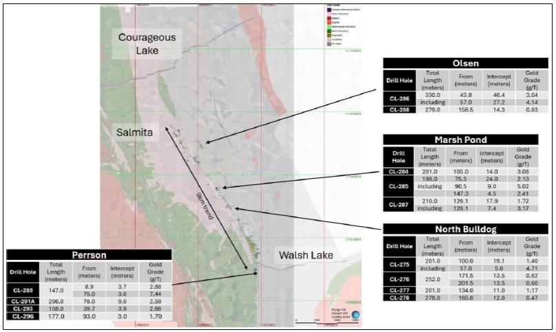
Source: Seabridge Gold, 2025
Focus will be on structural and geological controls on Olsen
and Marsh Pond targets which are considered most prospective. Work includes:
| ● | mapping, sampling and geophysics is budgeted to refine these targets |
| ● | relogging and mapping of further targets across 9 km trend to understand and recommend additional opportunities |
| ● | initiate baseline environmental studies |
| ● | maintenance of camp and preparation for Phase 2 drilling program. |
| Courageous Lake Project | Page 403 |
| Pre-feasibility Study and Preliminary Economic Assessment NI 43-101 Technical Report | January 5, 2024 |
Drilling at Walsh Lake to provide sufficient drilling to
upgrade the inferred resource to an indicated resource for incorporation in PFS, and drill test additional targets along Tundra-Salmita
trend to add to resource estimate.
| ● | Infill drilling at Walsh Lake (10 holes totalling 4,000 m). |
| ● | Drilling will provide confirmation of confidence in the resource. Addition of Walsh Lake to the mine
plan can have a meaningful impact on project economics. |
| ● | Drill tests at Marsh Pond and Olsen (three holes each and 1,500 and 1,000 m respectively). |
| ● | Follow up on prospective hits from 2018 drill program. Goal to define continuity of grade across a strike
length that are like Walsh Lake and therefore have meaningful impact on economics. Total drilling of 7,000 m. |
| ● | Second priority drill targets have been identified (totalling 11,000 m) that can be drilled contingent
on more pierce points being required at Walsh Lake and more follow up work at the further targets. |
| ● | Winter drilling allows optimal drill testing of deposits near lakes. |
| ● | Access by ice road- 350 k budget for the spur construction. Offset by savings for mobilisation/demobe
of drill and fuel hauls. |
| Courageous Lake Project | Page 404 |
| Pre-feasibility Study and Preliminary Economic Assessment NI 43-101 Technical Report | January 5, 2024 |
Ausenco. (2023): Ausenco Rev. C Load List dated 2023-11-14,
and an Ausenco Email of 14 Nov. 2023.
Bleeker, et al. (1999): The central Slave basement
complex, Part I: its structural topology and autochthonous cover. Canadian Journal of Earth Sciences, Vol. 36, p. 1083-1109.
Brown, J.,
Ferrians, O., Heginbottom, J.A., Melnikov, E. (2002): Circum-Arctic Map of Permafrost and Ground-Ice Conditions. Version 2. Boulder, Colorado
USA. NSIDC: National Snow and Ice Data Center.
Canadian
Institute of Mining, Metallurgy and Petroleum (CIM). (2019): Estimation of Mineral Resources and Mineral Reserves, Best Practice Guidelines:
Canadian Institute of Mining, Metallurgy and Petroleum, November 29, 2019.
Canadian
Institute of Mining, Metallurgy and Petroleum (CIM). (2014): CIM Standards for Mineral Resources and Mineral Reserves, Definitions and
Guidelines: Canadian Institute of Mining, Metallurgy and Petroleum, May 2014.
COSEWIC.
(2009): COSEWIC assessment and status report on the Horned Grebe Podiceps auritus, Western population and Magdalen Islands population,
in Canada. Committee on the Status of Endangered Wildlife in Canada. Ottawa. vii + 42 pp. (www.sararegistry.gc.ca/status/status_e.cfm).
Dillon-Leitch,
H. (1981): Volcanic stratigraphy, structure, and metamorphism in the Courageous-MacKay Lake greenstone belt, Slave Province, Northwest
Territories. Unpublished M.Sc. Thesis, University of Ottawa.
EBA. (2002):
Draft Report Environmental Due Diligence Review, Courageous Lake Property. Independent report for Seabridge Gold; 28 p.
EBA. (2006):
Geotechnical Site Investigations at the Courageous Lake Property, Northwest Territories (Project 1700201). Internal report prepared by
EBA for Seabridge Gold Inc. September 2006.
EBA. (2010):
Proposed Courageous Lake Mine Site Development, Geotechnical Investigation (Project Number E14101103). Internal report prepared by EBA
Engineering Consultants Ltd. for Seabridge Gold Inc. October 2010.
EBA. (2011):
Proposed Courageous Lake Mine Site Development Phase 2 Infrastructure Geotechnical Investigation Data Report – March-April 2011
(Project number E14101103). Internal report prepared by EBA for Seabridge Gold Inc July 2011.
EBA. (2012):
Proposed Courageous Lake Mine Site Development, Diversion Channel Options, Process Plant Site (Option 1) and Airstrip Extension Geotechnical
Investigation Report – March 2012 (File E14101187). Internal report prepared by EBA for Seabridge Gold Inc. May 2012.
ERM. (2019):
Courageous Lake Project: Caribou Camera Report 2011 – 2018. Internal report prepared by Environmental Resources Management Vancouver,
BC, for Seabridge Gold Inc.
| Courageous Lake Project | Page 405 |
| Pre-feasibility Study and Preliminary Economic Assessment NI 43-101 Technical Report | January 5, 2024 |
ERM. (2020):
Courageous Lake Project: Caribou Camera Program Summary 2011 – 2019. Internal report prepared by Environmental Resources Management
Vancouver, BC, for Seabridge Gold Inc.
ERM. (2023):
Courageous Lake Project: Caribou Camera Program Summary 2019 – 2023. Internal report prepared by Environmental Resources Management
Vancouver, BC, for Seabridge Gold Inc.
ERM. (2023):
Courageous Lake Project: Caribou Camera Report, 2023. Internal report prepared by Environmental Resources Management Vancouver, BC, for
Seabridge Gold Inc.
ERM. (2023): Courageous Lake
Project: Final Report on Northwest Territories Act Class 2 Archaeologist’s Permit # 2022-003. Internal report prepared by
Environmental Resources Management Vancouver, BC, for Seabridge Gold Inc.
Golder. (2010a):
Hydrogeological Field Investigation Program and Borehole Instrumentation, Courageous Lake Project (DCN 010). Internal report prepared
by Golder Associates Ltd. for Seabridge Gold Inc. December 23, 2010.
Golder.
(2010b): Groundwater Conductivity and Inferred Salinity (DCN 012). Internal report prepared by Golder Associates Ltd. for Seabridge Gold
Inc. December 2010.
Golder.
(2010c): Preliminary Estimate of Water Inflows to the Proposed Courageous Lake Project Open Pit (DCN 013). Internal report prepared by
Golder Associates Ltd. for Seabridge Gold Inc. December 22, 2010. Technical Memorandum.
Golder. (2011a):
Pre-Feasibility Level Pit Slope Design Criteria for the FAT Deposit, Courageous Lake Project (DCN 018). Internal report prepared by
Golder Associates Ltd. for Seabridge Gold Inc. May 18, 2011.
Golder. (2011b): 2011
Geotechnical and Hydrogeological Field Investigations, Courageous Lake Project (DCN 033). Internal report prepared by Golder
Associates Ltd. for Seabridge Gold Inc. December 5, 2011.
Golder.
(2012a): Review of 2011 Westbay Development and Sampling Program. Internal Technical Memorandum prepared by Golder Associates Ltd. for
Seabridge Gold Inc. June 5, 2012.
Golder. (2012b):
Courageous Lake Project – Hydrogeology Model Sensitivity Study. Internal Technical Memorandum prepared by Golder Associates Ltd.
for Seabridge Gold Inc. June 6, 2012.
Government of Canada.
(2021): 2020 National Building Code of Canada Seismic Hazard Tool.
<https://earthquakescanada.nrcan.gc.ca/hazard-alea/interpolat/nbc2020-cnb2020-en.php>.
Government of Northwest Territories.
(2020): Slave Geological Province Corridor Project. <https://www.inf.gov.nt.ca/en/SGP>.
Hatch Ltd. (2005): Courageous
Lake Project, Preliminary Assessment, NI 43-101 Technical Report, p. 179. <www.sedar.com>.
Henderson,
J. F. (1943): Structure and Metamorphism of early Precambrian rocks between Gordon Lake and Great Slave Lake; Northwest Territories. Am.
Journal of Sci., Vol. 241, pp 430-446.
| Courageous Lake Project | Page 406 |
| Pre-feasibility Study and Preliminary Economic Assessment NI 43-101 Technical Report | January 5, 2024 |
Indian and
Northern Affairs Canada. (2002): Mine Site Reclamation Policy for the Northwest Territories. A policy for the protection of the environment
and the disposition of liability relating to mine closures in the Northwest Territories.
Johnson, M.
(1990): Report on Magnetic and Induced Polarization Surveys. Internal report prepared by Covello, Bryan and Associates Ltd. for Placer
Dome Exploration.
Kemp, R. (1987): Report on Exploration
Work, Tundra Gold Venture 1986-87. Internal report prepared by Noranda Exploration Company Limited; p. 34.
Mackenzie Valley Land and Water Board. (2023):
Home | Mackenzie Valley Land and Water Board (mvlwb.com)
Mackenzie Valley Review Board. (2023): Home | Review Board
Martin et al. (2013): A
Method for Deriving Sub-Permafrost Groundwater Salinity and Total Dissolved Solids. Proceedings from Mine Water Solutions in Extreme
Environments, April. Lima, Peru.
NRC Publications Archive. (1968):
Guide to a Field Description of Permafrost for Engineering Purposes. Pihlainen, J.A., NRCC-7576
Read, J., Stacey, P. (2009): Guidelines for Open Pit Slope
Design. CSIRO Publishing, Australia.
RMI. (2002):
Technical review of the Courageous Lake property, Northwest Territories, Canada, July 8, 2002, technical report prepared for Seabridge
Gold Inc., 61 pages.
RMI. (2004): Technical Review of the Courageous Lake Property,
Northwest Territories, Canada. December 30, 2004.
RMI. (2007): Updated Mineral
Resource Estimate Courageous Lake Project, Northwest Territories, Canada. February 22, 2007.
Tetra Tech Wardrop. (2012): Courageous Lake Pre-feasibility
Study. Tetra Tech Wardrop, September 5, 2012.
Tetra Tech.
(2023a): Seabridge Courageous Lake Gap Assessment and Conformance Review of “Pre-Feasibility Level Pit Slope Design Criteria for
the FAT Deposit, Courageous Lake Project. Golder, 18 May 2011, Document number 018 Ver. 0. Report”. Tetra Tech Canada Inc. 08 December
2023, Technical Memorandum.
Tetra Tech.
(2023b): Courageous Lake Project, 2023 Pre-Feasibility Open Pit Slope Design Update. Tetra Tech Canada Inc. 08 December 2023, Technical
Report.
The Claim
Group. (2023): 5073 NWT Ltd./Seabridge Gold Inc., Courageous Lake Property. Independent report for Seabridge Gold (December 2, 2023).
p.3.
TJS. (2005):
Seabridge Gold Inc. Courageous Lake Project Preliminary Technical Assessment. Internal report prepared by TJS Mining-Met Services Inc.
for Seabridge Gold Inc., September 7, 2005.
| Courageous Lake Project | Page 407 |
| Pre-feasibility Study and Preliminary Economic Assessment NI 43-101 Technical Report | January 5, 2024 |
Wardrop. (2008): Courageous
Lake Preliminary Economic Assessment – 2008 (Doc. No. 0652880101-REP-R0002-00). Internal report prepared by Wardrop for
Seabridge Gold Inc.
Wardrop.
(2011): Courageous Lake Updated Preliminary Economic Assessment – 2011 (Doc. No. 0952880100-REP-R0001-02). Internal report prepared
by Wardrop for Seabridge Gold Inc. July 15, 2011.
Wardrop.
(2012): Courageous Lake Pre-feasibility Study. Internal report prepared by Tetra Tech Wardrop for Seabridge Gold Inc. September 5, 2012.
WSP. (2023a):
Courageous Lake Project Updated Hydrogeological Assessment (Doc. No. 2023CA96297-004-PP-RevA). Internal PowerPoint Presentation Summary
prepared by WSP Limited for Seabridge Gold Inc. November 3, 2023.
WSP. (2023b):
Hydrogeological Assessment for the Courageous Lake Project in Support of the Pre-feasibility Study and Preliminary Economical Assessment.
Internal Technical Memorandum prepared by WSP for Seabridge Gold Inc. November 30, 2023.
| Courageous Lake Project | Page 408 |
| Pre-feasibility Study and Preliminary Economic Assessment NI 43-101 Technical Report | January 5, 2024 |
.